
2013 Nº 6 Diciembre | December | 2013 15 e Español ... · Balance de Planta (BOP). Cada grupo...
6
Nº 6 Diciembre | December | 2013 | 15 e Español | Inglés | Spanish | English EOLICA OFFSHORE | OFFSHORE WIND REPORTAJE: CTCC INDIA URQUIA (VENEZUELA) | PLANT REPORT: CCCP INDIA URQUIA (VENEZUELA) EFICIENCIA ENERGÉTICA | ENERGY EFFICIENCY ENERGY E FuturENER GY PROYECTOS, TECNOLOGÍA Y ACTUALIDAD ENERGÉTICA PROJECTS, TECHNOLOGIES AND NERGY NEWS
Transcript of 2013 Nº 6 Diciembre | December | 2013 15 e Español ... · Balance de Planta (BOP). Cada grupo...

Nº 6 Diciembre | December | 2013 | 15 e Español | Inglés | Spanish | English
EOLICA OFFSHORE | OFFSHORE WIND REPORTAJE: CTCC INDIA URQUIA (VENEZUELA) | PLANT REPORT: CCCP INDIA URQUIA (VENEZUELA)
EFICIENCIA ENERGÉTICA | ENERGY EFFICIENCY
ENERGYE
FuturENERGYP R O Y E C T O S , T E C N O L O G Í A Y A C T U A L I D A D E N E R G É T I C AP R O J E C T S , T E C H N O L O G I E S A N D N E R G Y N E W S
Nº
6 |
Dic
iem
bre
Dec
emb
er 2
013
Futu
rEN
ERG
YP
RO
YE
CT
OS
, T
EC
NO
LO
GÍA
Y A
CT
UA
LID
AD
EN
ER
GÉ
TIC
AP
RO
JE
CT
S,
TE
CH
NO
LO
GIE
S A
ND
EN
ER
GY
NE
WS
verd
e E p
anto
ne 3
56 C
verd
e N p
anto
ne 3
62 C
verd
e E p
anto
ne 3
68 C
allo
R p
anto
ne 3
945
Cna
ranj
a G p
anto
ne 7
16 C
rojo
Y p
anto
ne 4
85 C
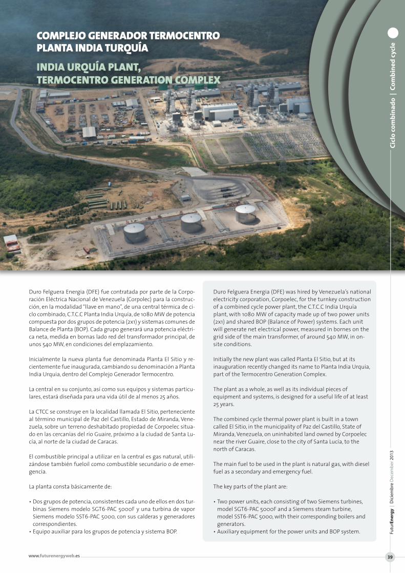
Duro Felguera Energia (DFE) fue contratada por parte de la Corpo-ración Eléctrica Nacional de Venezuela (Corpolec) para la construc-ción, en la modalidad “llave en mano”, de una central térmica de ci-clo combinado, C.T.C.C Planta India Urquía, de 1080 MW de potencia compuesta por dos grupos de potencia (2x1) y sistemas comunes de Balance de Planta (BOP). Cada grupo generará una potencia eléctri-ca neta, medida en bornas lado red del transformador principal, de unos 540 MW, en condiciones del emplazamiento.
Inicialmente la nueva planta fue denominada Planta El Sitio y re-cientemente fue inaugurada, cambiando su denominación a Planta India Urquia, dentro del Complejo Generador Termocentro.
La central en su conjunto, así como sus equipos y sistemas particu-lares, estará diseñada para una vida útil de al menos 25 años.
La CTCC se construye en la localidad llamada El Sitio, perteneciente al término municipal de Paz del Castillo, Estado de Miranda, Vene-zuela, sobre un terreno deshabitado propiedad de Corpoelec situa-do en las cercanías del río Guaire, próximo a la ciudad de Santa Lu-cía, al norte de la ciudad de Caracas.
El combustible principal a utilizar en la central es gas natural, utili-zándose también fueloil como combustible secundario o de emer-gencia.
La planta consta básicamente de:
• Dos grupos de potencia, consistentes cada uno de ellos en dos tur-binas Siemens modelo SGT6-PAC 5000F y una turbina de vapor Siemens modelo SST6-PAC 5000, con sus calderas y generadores correspondientes.
• Equipo auxiliar para los grupos de potencia y sistema BOP.
Duro Felguera Energia (DFE) was hired by Venezuela’s national electricity corporation, Corpoelec, for the turnkey construction of a combined cycle power plant, the C.T.C.C India Urquía plant, with 1080 MW of capacity made up of two power units (2x1) and shared BOP (Balance of Power) systems. Each unit will generate net electrical power, measured in bornes on the grid side of the main transformer, of around 540 MW, in on-site conditions.
Initially the new plant was called Planta El Sitio, but at its inauguration recently changed its name to Planta India Urquia, part of the Termocentro Generation Complex.
The plant as a whole, as well as its individual pieces of equipment and systems, is designed for a useful life of at least 25 years.
The combined cycle thermal power plant is built in a town called El Sitio, in the municipality of Paz del Castillo, State of Miranda, Venezuela, on uninhabited land owned by Corpoelec near the river Guaire, close to the city of Santa Lucía, to the north of Caracas.
The main fuel to be used in the plant is natural gas, with diesel fuel as a secondary and emergency fuel.
The key parts of the plant are:
• Two power units, each consisting of two Siemens turbines, model SGT6-PAC 5000F and a Siemens steam turbine, model SST6-PAC 5000, with their corresponding boilers and generators.
• Auxiliary equipment for the power units and BOP system.
COMPLEJO GENERADOR TERMOCENTROPLANTA INDIA TURQUÍA
INDIA URQUÍA PLANT,TERMOCENTRO GENERATION COMPLEX
Cic
lo c
om
bin
ado
| C
om
bin
ed c
ycle
Fu
turE
ner
gy
| D
icie
mb
re D
ecem
ber
201
3
www.futurenergyweb.es 39
ww
w.fu
ture
nvi
ro.e
sC
iclo
co
mb
inad
o |
Co
mb
ined
cyc
le
FuturEnergy | Diciembre December 201340
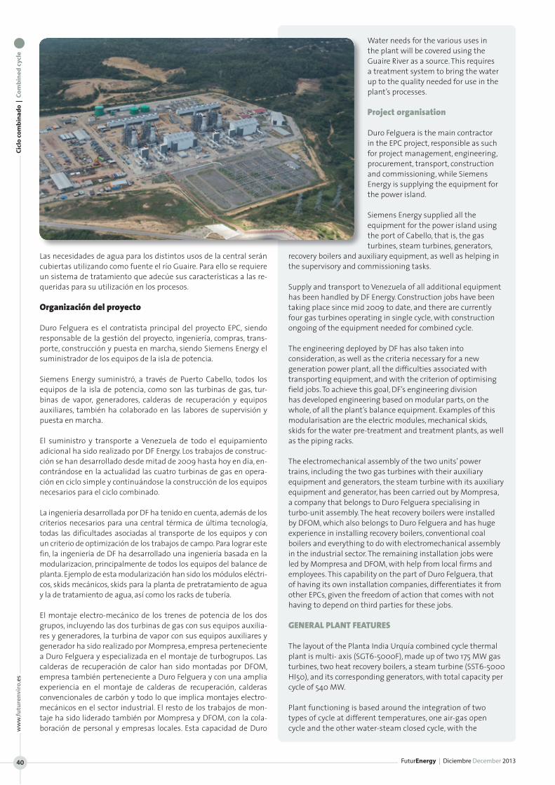
Las necesidades de agua para los distintos usos de la central serán cubiertas utilizando como fuente el río Guaire. Para ello se requiere un sistema de tratamiento que adecúe sus características a las re-queridas para su utilización en los procesos. Organización del proyecto
Duro Felguera es el contratista principal del proyecto EPC, siendo responsable de la gestión del proyecto, ingeniería, compras, trans-porte, construcción y puesta en marcha, siendo Siemens Energy el suministrador de los equipos de la isla de potencia.
Siemens Energy suministró, a través de Puerto Cabello, todos los equipos de la isla de potencia, como son las turbinas de gas, tur-binas de vapor, generadores, calderas de recuperación y equipos auxiliares, también ha colaborado en las labores de supervisión y puesta en marcha.
El suministro y transporte a Venezuela de todo el equipamiento adicional ha sido realizado por DF Energy. Los trabajos de construc-ción se han desarrollado desde mitad de 2009 hasta hoy en día, en-contrándose en la actualidad las cuatro turbinas de gas en opera-ción en ciclo simple y continuándose la construcción de los equipos necesarios para el ciclo combinado.
La ingeniería desarrollada por DF ha tenido en cuenta, además de los criterios necesarios para una central térmica de última tecnología, todas las dificultades asociadas al transporte de los equipos y con un criterio de optimización de los trabajos de campo. Para lograr este fin, la ingeniería de DF ha desarrollado una ingeniería basada en la modularizacion, principalmente de todos los equipos del balance de planta. Ejemplo de esta modularización han sido los módulos eléctri-cos, skids mecánicos, skids para la planta de pretratamiento de agua y la de tratamiento de agua, así como los racks de tubería.
El montaje electro-mecánico de los trenes de potencia de los dos grupos, incluyendo las dos turbinas de gas con sus equipos auxilia-res y generadores, la turbina de vapor con sus equipos auxiliares y generador ha sido realizado por Mompresa, empresa perteneciente a Duro Felguera y especializada en el montaje de turbogrupos. Las calderas de recuperación de calor han sido montadas por DFOM, empresa también perteneciente a Duro Felguera y con una amplia experiencia en el montaje de calderas de recuperación, calderas convencionales de carbón y todo lo que implica montajes electro-mecánicos en el sector industrial. El resto de los trabajos de mon-taje ha sido liderado también por Mompresa y DFOM, con la cola-boración de personal y empresas locales. Esta capacidad de Duro
Water needs for the various uses in the plant will be covered using the Guaire River as a source. This requires a treatment system to bring the water up to the quality needed for use in the plant’s processes.
Project organisation
Duro Felguera is the main contractor in the EPC project, responsible as such for project management, engineering, procurement, transport, construction and commissioning, while Siemens Energy is supplying the equipment for the power island.
Siemens Energy supplied all the equipment for the power island using the port of Cabello, that is, the gas turbines, steam turbines, generators,
recovery boilers and auxiliary equipment, as well as helping in the supervisory and commissioning tasks.
Supply and transport to Venezuela of all additional equipment has been handled by DF Energy. Construction jobs have been taking place since mid 2009 to date, and there are currently four gas turbines operating in single cycle, with construction ongoing of the equipment needed for combined cycle.
The engineering deployed by DF has also taken into consideration, as well as the criteria necessary for a new generation power plant, all the difficulties associated with transporting equipment, and with the criterion of optimising field jobs. To achieve this goal, DF’s engineering division has developed engineering based on modular parts, on the whole, of all the plant’s balance equipment. Examples of this modularisation are the electric modules, mechanical skids, skids for the water pre-treatment and treatment plants, as well as the piping racks.
The electromechanical assembly of the two units’ power trains, including the two gas turbines with their auxiliary equipment and generators, the steam turbine with its auxiliary equipment and generator, has been carried out by Mompresa, a company that belongs to Duro Felguera specialising in turbo-unit assembly. The heat recovery boilers were installed by DFOM, which also belongs to Duro Felguera and has huge experience in installing recovery boilers, conventional coal boilers and everything to do with electromechanical assembly in the industrial sector. The remaining installation jobs were led by Mompresa and DFOM, with help from local firms and employees. This capability on the part of Duro Felguera, that of having its own installation companies, differentiates it from other EPCs, given the freedom of action that comes with not having to depend on third parties for these jobs.
GENERAL PLANT FEATURES
The layout of the Planta India Urquía combined cycle thermal plant is multi- axis (SGT6-5000F), made up of two 175 MW gas turbines, two heat recovery boilers, a steam turbine (SST6-5000 HI50), and its corresponding generators, with total capacity per cycle of 540 MW.
Plant functioning is based around the integration of two types of cycle at different temperatures, one air-gas open cycle and the other water-steam closed cycle, with the
Cic
lo c
om
bin
ado
| C
om
bin
ed c
ycle
Fu
turE
ner
gy
| D
icie
mb
re D
ecem
ber
201
3
www.futurenergyweb.es 41
Felguera, contar con empresas propias de montaje, le hace diferen-ciarse del resto de los EPCs, dada la autonomía que supone no tener que contar con terceras partes para estos trabajos.
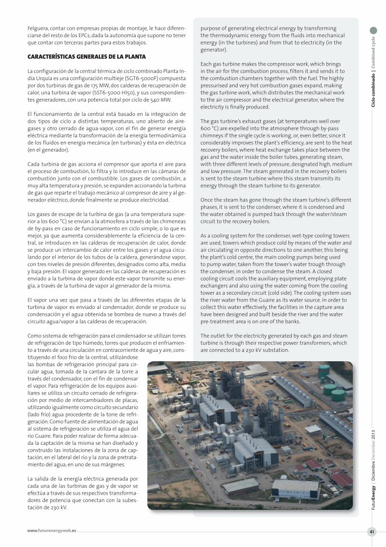
CARACTERÍSTICAS GENERALES DE LA PLANTA
La configuración de la central térmica de ciclo combinado Planta In-dia Urquía es una configuración multieje (SGT6-5000F) compuesta por dos turbinas de gas de 175 MW, dos calderas de recuperación de calor, una turbina de vapor (SST6-5000 HI50), y sus correspondien-tes generadores, con una potencia total por ciclo de 540 MW.
El funcionamiento de la central está basado en la integración de dos tipos de ciclo a distintas temperaturas, uno abierto de aire-gases y otro cerrado de agua-vapor, con el fin de generar energía eléctrica mediante la transformación de la energía termodinámica de los fluidos en energía mecánica (en turbinas) y ésta en eléctrica (en el generador).
Cada turbina de gas acciona el compresor que aporta el aire para el proceso de combustión, lo filtra y lo introduce en las cámaras de combustión junto con el combustible. Los gases de combustión, a muy alta temperatura y presión, se expanden accionando la turbina de gas que reparte el trabajo mecánico al compresor de aire y al ge-nerador eléctrico, donde finalmente se produce electricidad.
Los gases de escape de la turbina de gas (a una temperatura supe-rior a los 600 °C) se envían a la atmosfera a través de las chimeneas de by-pass en caso de funcionamiento en ciclo simple, o lo que es mejor, ya que aumenta considerablemente la eficiencia de la cen-tral, se introducen en las calderas de recuperación de calor, donde se produce un intercambio de calor entre los gases y el agua circu-lando por el interior de los tubos de la caldera, generándose vapor, con tres niveles de presión diferentes, designados como alta, media y baja presión. El vapor generado en las calderas de recuperación es enviado a la turbina de vapor donde este vapor transmite su ener-gía, a través de la turbina de vapor al generador de la misma.
El vapor una vez que pasa a través de las diferentes etapas de la turbina de vapor es enviado al condensador, donde se produce su condensación y el agua obtenida se bombea de nuevo a través del circuito agua/vapor a las calderas de recuperación.
Como sistema de refrigeración para el condensador se utilizan torres de refrigeración de tipo húmedo, torres que producen el enfriamien-to a través de una circulación en contracorriente de agua y aire, cons-tituyendo el foco frio de la central, utilizándose las bombas de refrigeración principal para cir-cular agua, tomada de la cantara de la torre a través del condensador, con el fin de condensar el vapor. Para refrigeración de los equipos auxi-liares se utiliza un circuito cerrado de refrigera-ción por medio de intercambiadores de placas, utilizando igualmente como circuito secundario (lado frío) agua procedente de la torre de refri-geración. Como fuente de alimentación de agua al sistema de refrigeración se utiliza el agua del río Guaire. Para poder realizar de forma adecua-da la captación de la misma se han diseñado y construido las instalaciones de la zona de cap-tación, en el lateral del río y la zona de pretrata-miento del agua, en uno de sus márgenes.
La salida de la energía eléctrica generada por cada una de las turbinas de gas y de vapor se efectúa a través de sus respectivos transforma-dores de potencia que conectan con la subes-tación de 230 kV.
purpose of generating electrical energy by transforming the thermodynamic energy from the fluids into mechanical energy (in the turbines) and from that to electricity (in the generator).
Each gas turbine makes the compressor work, which brings in the air for the combustion process, filters it and sends it to the combustion chambers together with the fuel. The highly pressurised and very hot combustion gases expand, making the gas turbine work, which distributes the mechanical work to the air compressor and the electrical generator, where the electricity is finally produced.
The gas turbine’s exhaust gases (at temperatures well over 600 °C) are expelled into the atmosphere through by-pass chimneys if the single cycle is working, or, even better, since it considerably improves the plant’s efficiency, are sent to the heat recovery boilers, where heat exchange takes place between the gas and the water inside the boiler tubes, generating steam, with three different levels of pressure, designated high, medium and low pressure. The steam generated in the recovery boilers is sent to the steam turbine where this steam transmits its energy through the steam turbine to its generator. Once the steam has gone through the steam turbine’s different phases, it is sent to the condenser, where it is condensed and the water obtained is pumped back through the water/steam circuit to the recovery boilers.
As a cooling system for the condenser, wet-type cooling towers are used, towers which produce cold by means of the water and air circulating in opposite directions to one another, this being the plant’s cold centre, the main cooling pumps being used to pump water, taken from the tower’s water trough through the condenser, in order to condense the steam. A closed cooling circuit cools the auxiliary equipment, employing plate exchangers and also using the water coming from the cooling tower as a secondary circuit (cold side). The cooling system uses the river water from the Guaire as its water source. In order to collect this water effectively, the facilities in the capture area have been designed and built beside the river and the water pre-treatment area is on one of the banks.
The outlet for the electricity generated by each gas and steam turbine is through their respective power transformers, which are connected to a 230 kV substation.
ww
w.fu
ture
nvi
ro.e
sC
iclo
co
mb
inad
o |
Co
mb
ined
cyc
le
FuturEnergy | Diciembre December 201342
PRODUCCIÓN Y CONSUMOS
Producción
La potencia eléctrica del grupo multieje es de unos 1.080 MW.
Consumos de combustible
Esta central utiliza como combustible principal gas natural para ali-mentar a las turbinas de gas. Se utiliza gasóleo como combustible secundario o de emergencia, empleándose también para alimentar los generadores diesel de emergencia y la bomba diesel del sistema de protección contra incendios.
Gas natural
El gas natural se recibe a través de la red gasista venezolana. Con-venientemente acondicionado para la operación continua de las turbinas, libre de condensados y de partículas.
El sistema de gas dentro de la planta de generación está compuesto por una línea de conexión a la red, un sistema de compresión de gas, formado por cinco compresores de gas, que aseguran unas con-diciones de presión y temperatura estables para el funcionamiento de las turbinas de gas, y por las líneas de distribución y alimenta-ción a las turbinas, así como un sistema de filtrado de gas, específi-co con filtros coalescentes de seguridad, previo a la entrada de los módulos de gas de cada turbina.
Gasoil
Se emplea como combustible alternativo para el funcionamiento es-porádico durante los periodos de interrupción de suministro de gas natural y como combustible de los equipos auxiliares mencionados anteriormente. Se dispone de almacenamiento de gasoil compuesto por tres tanques de almacenamiento de 5.000 m3 cada uno, una plan-ta de tratamiento del mismo, mediante centrifugas, contándose con capacidad de 10.000 m3 de gasoil tratado y 5.000 m3 de gasoil bruto. El gasoil además de alimentar a las turbinas de gas, también se utiliza como combustible en los generadores diesel de emergencia y para la bomba diesel del sistema de protección contra incendios.
Otros consumos
El suministro de agua clarificada para los diferentes consumos: planta de agua desmineralizada, agua de reposición para el circuito de refrigeración y agua de servicios procede de la planta de pretra-tamiento de agua del Río Guaire.
La central consume otros fluidos en cantidades mucho menores ta-les como nitrógeno para inertizar, aceites y grasas para lubricación, así como productos químicos de uso en el tratamiento del agua en la PPA, en la PTA y, en las torres de refrigeración y en el agua del ciclo agua-vapor.
ISLA DE POTENCIA
Turbina de gas
En la planta se han instalado dos turbinas de gas fabricadas por Sie-mens, modelo SGT6-PAC-5000F, por cada grupo, incluyendo carcasa acústica con ventilación forzada.
Turbina de vapor
Dada su configuración multieje, cada isla de potencia de la plan-ta contiene una turbina de vapor, fabricada por Siemens, modelo SST6-5000 IH50.
PRODUCTION & CONSUMPTION
Production
The multi-axis unit’s electrical capacity is about 1080 MW.
Fuel consumption
This plant uses natural gas as its main fuel to feed the gas turbines. Diesel fuel is employed as a secondary and emergency fuel, also being used to feed the emergency diesel generators and the fire protection system’s diesel pump.
Natural gas
Natural gas is received from Venezuela’s gas grid. This is converted for the turbines to operate continuously, free of condensates and particles.
The gas system inside the energy plant is made up of a connection line to the grid, a gas compression system, consisting of five gas compressors, which guarantee stable pressure and temperature conditions for the gas turbines to work, and by distribution and feed lines to the turbines, as well as a specific gas filtering system with coalescent security filters before the gas module intake to each turbine.
Diesel fuel
This is used as an alternative fuel for sporadic functioning during periods when natural gas supply is interrupted, and as fuel for the auxiliary equipment mentioned above. There is storage for the diesel fuel consisting of three storage tanks, each of 5000 m3, a treatment plant for the diesel fuel, with centrifuge, with capacity for 10,000 m3 of treated diesel fuel and 5000 m3 of untreated diesel fuel.
Diesel fuel, as well as feeding the gas turbines, is also used as fuel in the emergency diesel generators and for the fire protection system’s diesel pump.
Other usages
The clarified water supply for various uses: demineralised water plant, replacement water for the cooling circuit and water for bathrooms comes from the Guaire River’s water pre-treatment plant.
The plant consumes other fluids in much smaller quantities, such as nitrogen for inert processes, oils and fats for lubrication, as well as chemical products for use in treating water in the pre-treatment and treatment plants, in the cooling towers and in the water for the water-steam cycle.
POWER ISLAND
Gas turbine
Two gas turbines manufactured by Siemens, model SGT6-PAC-5000F, have been fitted for each unit, including a soundproofed housing with forced ventilation.
Steam turbine
Because of its multi-axis configuration, each power island in the plant has a steam turbine, manufactured by Siemens, model SST6-5000 IH50.
Cic
lo c
om
bin
ado
| C
om
bin
ed c
ycle
Fu
turE
ner
gy
| D
icie
mb
re D
ecem
ber
201
3
www.futurenergyweb.es 43
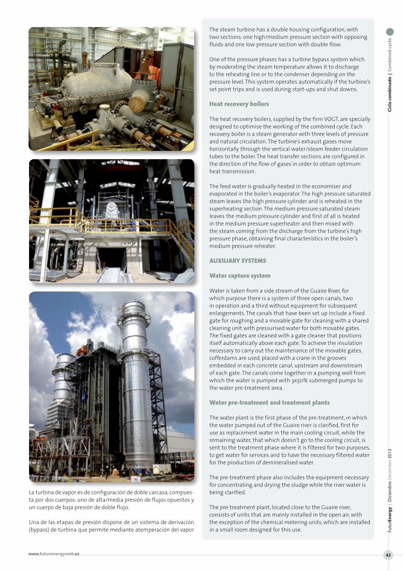
La turbina de vapor es de configuración de doble carcasa, compues-ta por dos cuerpos: uno de alta/media presión de flujos opuestos y un cuerpo de baja presión de doble flujo.
Una de las etapas de presión dispone de un sistema de derivación (bypass) de turbina que permite mediante atemperación del vapor
The steam turbine has a double housing configuration, with two sections: one high/medium pressure section with opposing fluids and one low pressure section with double flow.
One of the pressure phases has a turbine bypass system which by moderating the steam temperature allows it to discharge to the reheating line or to the condenser depending on the pressure level. This system operates automatically if the turbine’s set point trips and is used during start-ups and shut downs.
Heat recovery boilers
The heat recovery boilers, supplied by the firm VOGT, are specially designed to optimise the working of the combined cycle. Each recovery boiler is a steam generator with three levels of pressure and natural circulation. The turbine’s exhaust gases move horizontally through the vertical water/steam feeder circulation tubes to the boiler. The heat transfer sections are configured in the direction of the flow of gases in order to obtain optimum heat transmission.
The feed water is gradually heated in the economiser and evaporated in the boiler’s evaporator. The high pressure saturated steam leaves the high pressure cylinder and is reheated in the superheating section. The medium pressure saturated steam leaves the medium pressure cylinder and first of all is heated in the medium pressure superheater and then mixed with the steam coming from the discharge from the turbine’s high pressure phase, obtaining final characteristics in the boiler’s medium pressure reheater.
AUXILIARY SYSTEMS
Water capture system
Water is taken from a side stream of the Guaire River, for which purpose there is a system of three open canals, two in operation and a third without equipment for subsequent enlargements. The canals that have been set up include a fixed gate for roughing and a movable gate for cleaning with a shared cleaning unit with pressurised water for both movable gates. The fixed gates are cleaned with a gate cleaner that positions itself automatically above each gate. To achieve the insulation necessary to carry out the maintenance of the movable gates, cofferdams are used, placed with a crane in the grooves embedded in each concrete canal, upstream and downstream of each gate. The canals come together in a pumping well from which the water is pumped with 3x50% submerged pumps to the water pre-treatment area.
Water pre-treatment and treatment plants
The water plant is the first phase of the pre-treatment, in which the water pumped out of the Guaire river is clarified, first for use as replacement water in the main cooling circuit, while the remaining water, that which doesn’t go to the cooling circuit, is sent to the treatment phase where it is filtered for two purposes, to get water for services and to have the necessary filtered water for the production of demineralised water.
The pre-treatment phase also includes the equipment necessary for concentrating and drying the sludge while the river water is being clarified.
The pre-treatment plant, located close to the Guaire river, consists of units that are mainly installed in the open air, with the exception of the chemical metering units, which are installed in a small room designed for this use.