Algo sobre mícleantechchallenge.org/wp-content/uploads/2018/05/CTCM_230518_T... · Clasifica tu...
93
Transcript of Algo sobre mícleantechchallenge.org/wp-content/uploads/2018/05/CTCM_230518_T... · Clasifica tu...


Apasionado de la eco-innovación, las tecnologías
limpias y el emprendimiento. Profesional en
transferencia de tecnología, certificado por la
Universidad de California y miembro de Licensing
Executives Society International.
También soy emprendedor, voluntario y mentor.
Me encanta el buen café, el mezcal y la cerveza
artesanal. Melómano y DJ de hobbie, además de
cat-person.
Algo sobre mí

¿Y ustedes?

Contenido
1. Propiedad intelectual como estrategia
2. Tipos de propiedad intelectual*
• Signos distintivos
• Invenciones
• Patentes


Propiedad intelectial como estrategia

¿De donde nace la necesidad de tener propiedad intelectual?

CONOCIMIENTO
Intangible
Inconsumible
Transportable
Multiprósito
Acumulativo
No se puede devolver

Las barreras físicas y tecnológicas no son suficientes para proteger el conocimiento.
Se requiere otro intangible para evitar o impedir que otros usen la información sin autorización.

¿Cómo se manifiesta el conocimiento en una empresa?

Tecnología
Un sistema de conocimientos, técnicas, habilidades, pericias, y
organización utilizados para producir, comercializar y utilizar
bienes y servicios que satisfagan demandas sociales y
económicas.
Manual de Transferencia de Tecnología, ONUDI

Base Tecnológica
Conjunto de competencias centrales que le permiten a una empresa transformar
entradas (materias primas o información) en salidas (productos o servicios)
competitivamente. Depende de la experiencia interna de la empresa y del entorno.
Normalmente formada por:
• Conocimiento codificado.
• Maquinaria y equipo.
• Conocimiento inherente a las personas.
Manual de Transferencia de Tecnología, ONUDI
Relaciones
Convenios
Organización
Propiedad Intelectual y Convenios
Cocimiento
Propiedad Intelectual
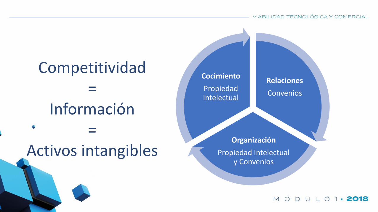
Competitividad=
Información=
Activos intangibles

Documentación en General
Patentes y Registros
Publicaciones Defensivas
Secretos Industriales
Círculos de la propiedad intelectual

Mejores prácticasDeterminar y
obtener PI
Asegurar libertad de operar y diseñar
Proteger y mantener vigente PI
Hacer valer PI
Inventariar conocimiento

Uso estratégico de PI
Imp
ort
anci
a
Tiempo
Secretos industriales

“La inteligencia consiste no sólo en el conocimiento, sino también en la destreza de aplicar los
conocimientos en la práctica”
Aristóteles


Know How
Expertisse
Diseño
Capacitación
Instrucciones
Mantenimiento
Instalación
Servicio
Refacciones
Producto
terminado
Estudios de
Mercado
Normas
Beneficios
económicos
Paquete Tecnológico
Mejoras
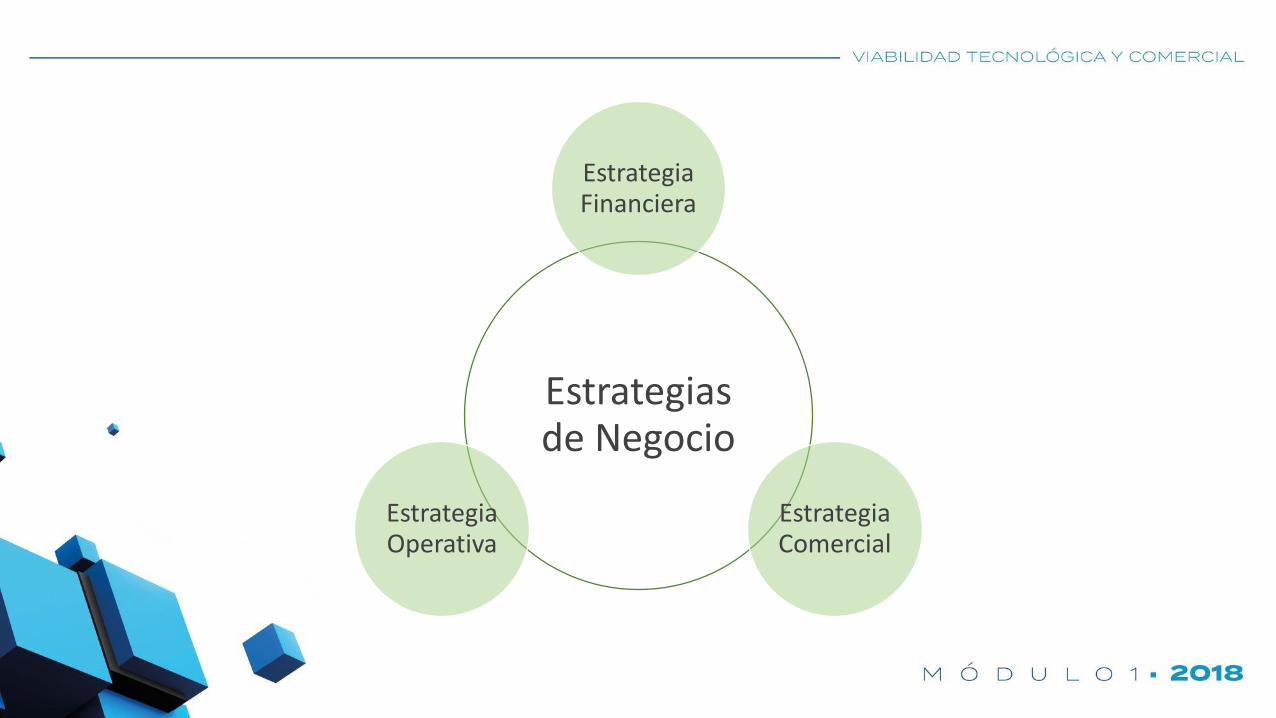
Estrategias de Negocio
Estrategia Financiera
Estrategia Comercial
Estrategia Operativa
Estrategias
de Negocio
Estrategia Financiera
Estrategia Comercial
Estrategia Operativa
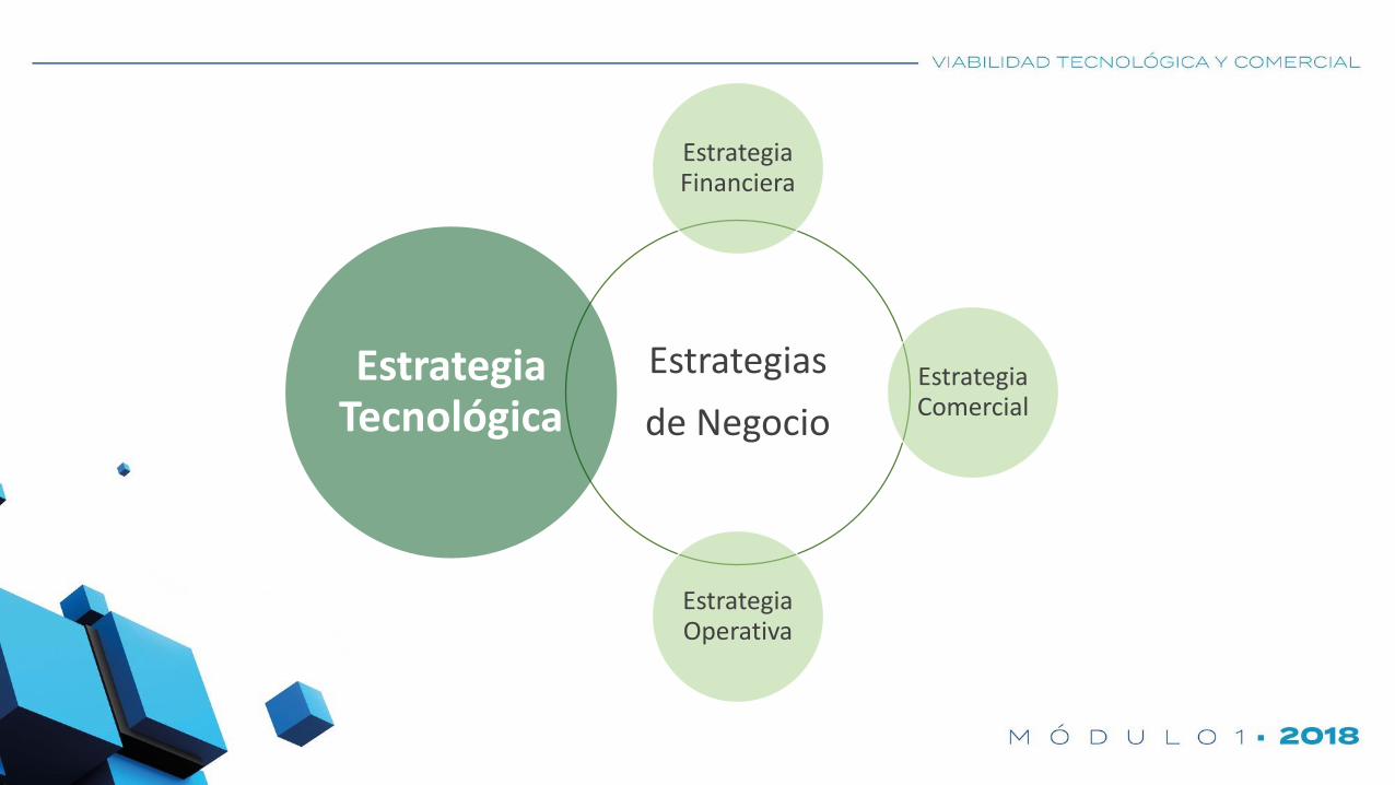
Estrategia Tecnológica

Actividad 1Estrategia

Estrategias
de Negocio
Estrategia Financiera
Estrategia Comercial
Estrategia Operativa
Estrategia Tecnológica
Protección Intelectual

Tipos de propiedad intelectual

¿Qué es la Propiedad
Intelectual?
¿En qué se basa?
¡Está vivo!
Rápido, llama a un
despacho de
propiedad intelectual.

DERECHOS DE PROPIEDAD INTELECTUAL (DPI)
“Conjunto de derechos que otorga el gobierno
sobre una creación intelectual que faculta a su
titular para el uso, gozo o disposición del bien,
con limitaciones o modalidades (tiempo,
territorio y extensión de aplicación) que fijan
las leyes.”

¿Para qué sirve?
• Obtener ingresos.
• Impedir invasión por terceros.
• Incentivar inversión en innovación.
• Facilitar la transacción de bienes (comercio).
• Difundir y permitir el acceso a la información.
• Imitar tecnología.
• Orientar la investigación.

Valor de Mercado vs. Capital Intelectual

Obtentor de Variedades Vegetales
Ley Federal de Variedades Vegetales
Servicio Nacional de Inspección y Certificación de Semillas
SAGARPA

Derechos de Autor
Ley Federal de Derechos de Autor
Instituto Nacional del Derecho de Autor
SEP

Obras Literarias – Música – Letras de Canciones – Obras Dramáticas – Danza
– Obras Pictóricas – Dibujos – Obras Plásticas – Comics – Obra
Arquitectónica – Obras Audiovisuales – Fotografía – Software – Diseño
Gráfico – Compilaciones – Diseño Textil – Derechos Conexos – Culturas
Populares – Derechos Reservados

Signos distitivos
Propiedad Industrial
Ley de Propiedad Industrial
Instituto Mexicano de la Propiedad Industrial
SE
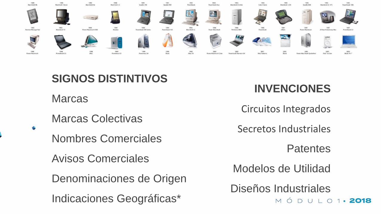
INVENCIONES
Circuitos Integrados
Secretos Industriales
Patentes
Modelos de Utilidad
Diseños Industriales
SIGNOS DISTINTIVOS
Marcas
Marcas Colectivas
Nombres Comerciales
Avisos Comerciales
Denominaciones de Origen
Indicaciones Geográficas*

SIGNOS
DISTINTIVOS

¿Qué es una Marca?
Todo signo perceptible por los sentidos y
susceptible de representarse.
10 años, con renovación indefinida.


Tipos de Marcas (Art. 89):
“Kisses”
Nominativa Figurativa
Mixta Tridimensional

¿Cómo se clasifican las Marcas?
Según la Clasificación de Niza:
Clases de Producto -> 1 a 34
Clases de Servicios -> 35 a 45

¿Qué son las Marcas Colectivas?
Art. 96
“Es la marca de una asociación o sociedad de productores,
fabricantes, comerciantes o prestadores de servicios, legalmente
constituidos.”
10 años, con renovación indefinida.

¿Qué son un Aviso Comercial?
SLOGAN
Art. 100
“Frase, enunciado, expresión u oración que tiene por objeto
anunciar, dar a conocer o hacer saber al público consumidor, la
existencia de productos o servicios en el mercado”
10 años, con renovación indefinida.

¿Qué es un Nombre Comercial?
Art. 105
“Identifica a una empresa o establecimiento industrial,
comercial o de servicios de giro determinado; con el derecho
a su uso exclusivo.”
10 años, con renovación indefinida.

¿Qué es la Denominación de Origen?
Art. 156
“Nombre de una región geográfica del país que se utiliza para
señalar un producto originario donde la calidad y las
características sean debidas exclusivamente al ambiente
geográfico, incluyendo factores naturales y humanos.”
Duración indefinida.

Pasos para registrar una marca
1.- Elige el tipo de marca que quieres registrar.
2.- Investiga que lo que pretendes registrar no incurra en las
prohibiciones establecidas en los artículos 4° y 90° de la LPI.
3.- Clasifica tu marca de acuerdo a la clasificación de niza.
4.- Realiza tu búsqueda.
5.- Llena tu formato y presentalo.

Solicitud de marca
Ingreso de Solicitud
Examen de Forma4 meses 6 meses
IMPI puede pedir aclaraciones o subsanaciones
Respuesta por solicitante
3 meses
IMPI resuelve para pasar a e. fondo
Co
n r
equ
eri
men
to
Examen de Forma1
1
INICIO FIN

5 pasos para registrar una marca en línea
1.- Ingresa a “marca en línea” desde el enlace que aparece en la página del impi.
2.- Crea una cuenta para obtener tu usuario y contraseña.
3.- Llena tu solicitud en línea, realiza el pago por transferencia electrónica o líne
de captura.
4.- Firma con tu fiel y envia.
5.- Ingresa habitualmente a tu tablero electrónico, donde podras encontrar
notificaciones sobre el trámite.
http://www.impi.gob.mx/cloud/Videos%20IMPI/marca_linea_201701e.mp4

Actividad 2Marca

Búsqueda de Marcashttp://marcanet.impi.gob.mx/
1. Verificar la clase del signo distintivo.
2. Escribir y buscar el signo distintivo.
3. Revisar la vigencia del registro.

INVENCIONES

¿Qué es un Secreto Industrial?
Art. 82
“Toda información comercial confidencial que confiera a una empresa
una ventaja competitiva. Los secretos comerciales abarcan los
secretos industriales o de fabricación y los secretos comerciales”

¿Cuánto dura de Secreto Industrial?
Ejemplos…

¿Cuándo es preferible mantener un Secreto Industrial?
✓ Cuando no es posible patentar.
✓ Cuando más de una empresa desea poseer y explotar la misma invención y/o
información.
✓ Cuando su valor técnico es menor al valor estratégico (comercial, p. ej.).
✓ Cuando se desea cubrir mayor territorio a menor costo.
✓ Cuando no se tiene capital para patentar.
✓ Cuando la patente sería fácil de replicar y/o mejorar.
¿Otras ideas?

¿Qué es un Circuito Integrado?
Art. 178bis
“Un producto en el que los elementos, de los cuales uno por lo menos
sea activo, y alguna o todas las interconexiones, formen parte
integrante del cuerpo y/o de la superficie de una pieza de material y
que esté destinado a realizar una función electrónica.”
15 años, sin renovación.

¿Qué es un Esquema de Trazado?
Art. 178bis
“Disposición tridimensional, expresada en cualquier forma, de los
elementos, de los cuales uno por lo menos sea activo, y de alguna o
todas las interconexiones de un circuito integrado, o dicha disposición
tridimensional preparada para un circuito integrado destinado a ser
fabricado.”
15 años, sin renovación.

PATENTES
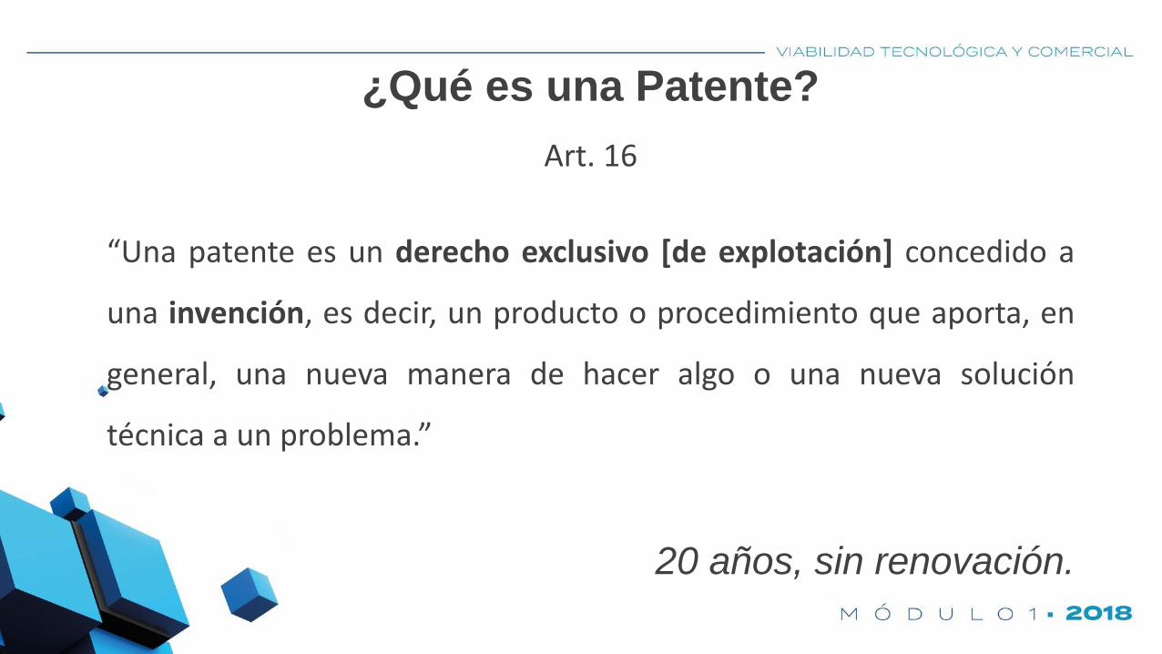
¿Qué es una Patente?
Art. 16
“Una patente es un derecho exclusivo [de explotación] concedido a
una invención, es decir, un producto o procedimiento que aporta, en
general, una nueva manera de hacer algo o una nueva solución
técnica a un problema.”
20 años, sin renovación.

Invención:
Art. 15
“Toda creación humana que permite transformar la materia o energía
existente en la naturaleza, para el aprovechamiento por el hombre y
satisfacer necesidades concretas.”

¿Qué necesita una Invención para
que se le conceda la Patente?

Requisitos:
NOVEDAD: Lo que no se encuentra en el estado de la técnica.
ACTIVIDAD INVENTIVA: Proceso creativo cuyos resultados no se deduzcan del
estado de la técnica en forma evidente para un técnico en la materia; es decir,
la “no obviedad”.
APLICACIÓN INDUSTRIAL: Posibilidad de que una invención pueda ser
producida o utilizada en cualquier rama de la actividad económica.

¿Estado de la técnica?
¿Técnico en la materia?
¿Producida o utilizada en cualquier rama de la actividad económica?


UNA PATENTE TARDA 3 AÑOS
(PROMEDIO) EN LLEGAR AL MERCADO……si es que llega

-
2,000
4,000
6,000
8,000
10,000
12,000
14,000
16,000
18,000
Otros
Suiza
España
Reino Unido
Japón
Italia
Francia
E.U.
Alemania
México
Solicitudes de Patente por Nacionalidad ante el IMPIAños MX
2002 526
2003 468
2004 565
2005 584
2006 574
2007 641
2008 685
2009 822
2010 951
2011 1,065
2012 1,292
2013 1,211
9,384

Años MX %
2002 139 26%
2003 121 26%
2004 162 29%
2005 131 22%
2006 132 23%
2007 199 31%
2008 197 29%
2009 213 26%
2010 229 24%
2011 245 23%
2012 281 22%
2013 302 25%
2,049 25%
Patentes otorgadas por nacionalidad en el IMPI
-
2,000
4,000
6,000
8,000
10,000
12,000
Otros
Suiza
Reino Unido
Japón
Francia
E.U.
Alemania
México

¿Qué es un Modelo de Utilidad?
Art. 28
“Objetos, utensilios, aparatos o herramientas. Modificaciones de
estructura, funciones, disposición, configuración o forma. Mejoras o
ventajas menores. Incluyen Dibujos y Modelos Industriales.”
10 años, sin renovación.


Requisitos:
NOVEDAD
APLICACIÓN INDUSTRIAL

¿Qué es un Diseño Industrial?
Art. 32
“Un diseño industrial es el aspecto ornamental o estético de un
artículo. El diseño industrial puede consistir en rasgos en tres
dimensiones (modelo), como la forma o superficie de un artículo, o
rasgos en dos dimensiones (dibujo), como el trazado, líneas o color.”
5 años, con renovación hasta 25 años*


Requisitos*:
NOVEDAD
Creación independiente
Grado significativo
APLICACIÓN INDUSTRIAL

NO se patentan:
✓ Procesos biológico esenciales.
✓ Material genético natural.
✓ Razas y variedades animales o vegetales.
✓ Cuerpo humano y partes vivas de este.
✓ Descubrimientos ya existentes en la naturaleza.
✓ Principios teóricos o científicos.
✓ Planes, reglas y métodos para realizar actos mentales, juegos o
negocios y métodos matemáticos.
✓ Programas de computación y formas de presentar la información.
✓ Creaciones estéticas y obras artísticas.
✓ Métodos de tratamiento médico.
✓ Mezclas y/o conjuntos de invenciones conocidas.
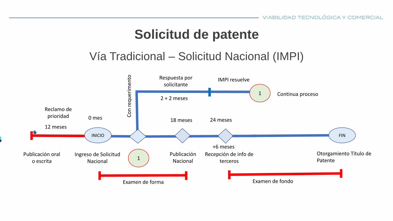
Solicitud de patente
Vía Tradicional – Solicitud Nacional (IMPI)
Ingreso de Solicitud Nacional
0 mes
INICIO FIN
18 meses
Publicación Nacional
Examen de forma
Otorgamiento Título de Patente
12 meses
Reclamo de prioridad
Publicación oral o escrita
Respuesta por solicitante
IMPI resuelve
Continua proceso1
Co
n r
equ
erim
ento
2 + 2 meses
1
+6 meses
Recepción de info de terceros
24 meses
Examen de fondo

¿Existen las patentes internacionales?
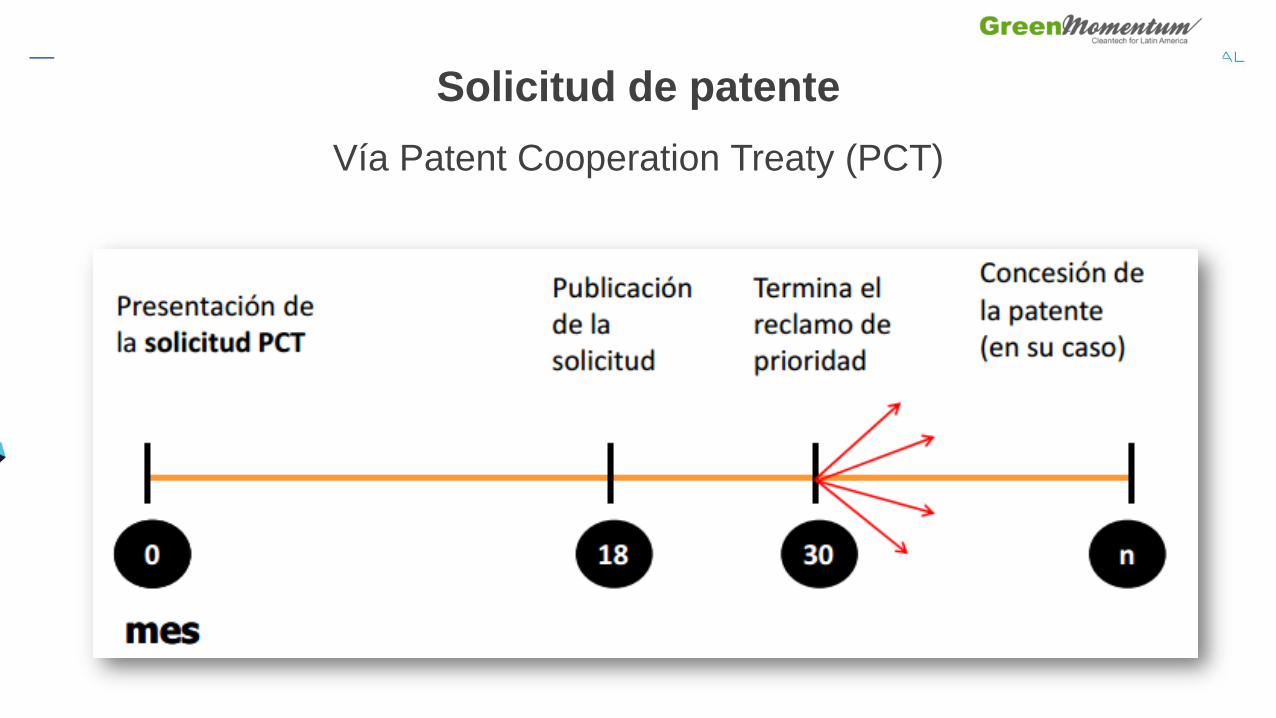
Solicitud de patente
Vía Patent Cooperation Treaty (PCT)

Solicitud de patente PCT
Mejor caso
Ingreso de Solicitud Nacional
12 meses
INICIO FIN
Ingresar Solicitud PCT
18 meses
Publicación Internacional
Inicia Fase Nacional
30 meses
Expira reclamo de prioridad
Otorgamiento Título de Patente
Toma de decisión de en que países proteger
Divulgación previaArt. 18
Una divulgación previa no afectará la novedad si:
✓ Dentro de los12 meses previos a la fecha de presentación de la
solicitud o de la fecha de prioridad, el inventor o titular dio a
conocer la invención.
✓ Al presentar la solicitud se incluye la documentación
comprobatoria.
Mitos
MITO 1: Patentes = a abogados.
MITO 2: Se roban las patentes, son mentira.
MITO 3: Las patentes en México son más tardadas.
MITO 4: Patente = Voy a ser rico.
MITO 5: Patente mundial.
MITO 6: Hay patentes sin valor científico o tecnológico.

¿Ese fue tu “movimiento patentado”?A mi me pareció arte previo…

Actividad 2Estrategia + Patente

Búsqueda de Patenteshttp://www.google.com/advanced_patent_search
1. Competidores.
2. Patentes.
3. Plan de mejora.

Cambios recientes en la LPI
Marcas sonoras u olfativas.
Indicaciones geográficas (marcas de certificación).
Trade dress.
Distintividad adquirida (secondary meaning)
Consentimiento de registro de marca semejante en grado de confusión.
Denegación de solicitudes de registro de marca de mala fe (nulidad de registro).
Diseño industrial también para objetos artesanales.

USOO792314.4B2
(12) United States Patent (10) Patent No.: US 7.923,144 B2 Kohn et al. (45) Date of Patent: *Apr. 12, 2011
(54) TUNABLE FRANGIBLE BATTERY PACK 5,444,378 A 8, 1995 Rogers SYSTEM 5,609.972 A 3, 1997 Kaschmitter et al.
5,667,907 A 9, 1997 Audit et al.
(75) Inventors: Scott Kohn, Menlo Park, CA (US); is: f 3.38 Matty al Gene Berdichevsky, Palo Alto, CA 6,399,238 B1 6/2002 Oweis et al. (US); Brian Charles Hewett, Los Alto 6,773.301 B1 8, 2004 Chaskin Hills, CA (US) 6,846, 186 B2 1/2005 Lao et al. ........................ 439/70
s 7,208,816 B2 4/2007 Kawakami et al. 7,671,565 B2 3/2010 Straubel et al.
(73) Assignee: Tesla Motors, Inc., Palo Alto, CA (US) 2001/0050608 A1 12/2001 Evans et al. - 2002/0022159 A1 2/2002 Pierson et al.
(*) Notice: Subject to any disclaimer, the term of this 2002fOO86578 A1 7, 2002 Ikeda patent is extended or adjusted under 35 2004/0137323 A1* 7/2004 Sato .............................. 429,185 U.S.C. 154(b) by 1046 days. 2004/O197642 A1* 10, 2004 Sato ........ ... 429,158
2005, 0164080 A1* 7/2005 KOZu et al. .................... 429, 176 This patent is Subject to a terminal dis- 2007/00 15061 A1 1/2007 Klaassen claimer. 2007/0188147 A1* 8, 2007 Straubel et al. ............... 320,134
* cited by examiner (21) Appl. No.: 11/731,574
Primary Examiner — Ula C Ruddock (22) Filed: Mar. 31, 2007 Assistant Examiner — Tony Chuo
O O (74) Attorney, Agent, or Firm — Patent Law Office of David (65) Prior Publication Data G. Beck
US 2008/O241667 A1 Oct. 2, 2008 (57) ABSTRACT
(51) Int. Cl. A tunable frangible battery pack system for use in an electric HOLM 2/06 (2006.01) vehicle is disclosed. The tunable frangible battery pack sys
(52) U.S. Cl. ........ 429/170; 429/156; 429/159: 429/163; tem includes a two piece clamshell housing. The system also 429/177 includes a plurality of battery cells arranged within the hous
(58) Field of Classification Search ........................ None ing and a collector plate secured to each piece of the housing. See application file for complete search history. The system also includes a wire conductor arranged between
each of the battery cells and collector plates to create a fran (56) References Cited gible disconnect system when the battery pack system and
U.S. PATENT DOCUMENTS
3,773,501 A * 1 1/1973 Nakajima et al. ............. 148,439 7, 1991 Sands et al. ................... 429/120 5,034,290 A *
electric Vehicle are exposed to a predetermined mechanical or thermal force or event.
12 Claims, 2 Drawing Sheets
U.S. Patent Apr. 12, 2011 Sheet 1 of 2 US 7.923,144 B2

U.S. Patent Apr. 12, 2011 Sheet 2 of 2 US 7.923,144 B2
- - - - - - - - - - - - - - - - - -

US 7,923,144 B2 1.
TUNABLE FRANGIBLE BATTERY PACK SYSTEM
BACKGROUND OF THE INVENTION
1. Field of the Invention The Subject invention generally relates to battery packs,
and more particularly relates to a tunable frangible battery pack system for use in a vehicle or other industrial equipment.
2. Description of Related Art Battery packs have been used for numerous years in elec
tric vehicles, such as automobiles, boats, aerospace vehicles, and within other industrial equipment applications. Many of the electrical systems used in these prior art vehicles and equipment are designed to minimize the possibility of short circuiting and to reduce the potential of Voltage exposure to emergency responders and other people in the general public. Such precautions help to reduce the possibility of an electro cution or other injury due to high Voltage encounters and situations. There have been many different attempts at pro viding an electric system that will disconnect electrical cir cuits due to a crash of a vehicle or high temperature situations in a vehicle or industrial equipment application. Many of these prior art systems will disconnect the battery from the circuits thus creating an open circuit and protecting any responders and other people from dangerous high Voltage situations. Generally, these prior art disconnect systems for battery packs will disconnect when a predetermined force is applied to the vehicle or equipment or if a predetermined thermal event occurs within the circuitry of the battery and/or electrical system. One of the prior art methodologies for disconnecting bat
tery cells uses a conductor wire that is either welded or bonded to a battery cell and is capable of being broken when a mechanical force is applied thereto. However, one problem with these prior art systems is that the mechanical strength of the breakable conductors was excessive and did not allow for the conductor to break unless the most extreme forces or situations acted on the vehicle or industrial equipment. There fore, the disconnecting of the power Supply system from the electrical vehicle or equipment did not occur during all emer gency situations as many designs originally called for. Fur thermore, the prior art methodologies of wire bonding the conductors to the cells did not provide a consistent fusing current mechanism Such that high thermal events would not break the conductor, thus leaving the equipment connected to circuits which may lead to electrocution and other injuries to users or responders to an accident scene. Other types of connecting wire conductors between battery cells and other equipment have been used, including various bonding tech niques for Smaller diameter wires, conductive epoxies for connection between a battery cell and a bus bar or collector plate, Soldering techniques that include solders made of nickel, tin, copper, plated metals, low metal alloys, etc. Fur thermore, other prior art methodologies have tried installation displacement connectors to connect the battery cell to a bus bar or collector plate, mechanical crimping or pressure crimp ing has also been used to connect battery cells to a bus bar. Furthermore, it should be noted that conductor materials used for prior art wire conductors include copper, gold, nickel, solder, indium, tin, aluminum, low melt alloys and the like.
However, there have been problems with the prior art dis connect systems and methodologies for an electrical system having a battery pack or like power Source. Some of the problems of the prior art include having the conductors arranged between battery cells and a bus bar or the like connected via bonding techniques that give the conductors
10
15
25
30
35
40
45
50
55
60
65
2 very high mechanical strengths that do not allow the conduc tor to break unless the most extreme situations occur Such as very high forces or extremely high heat. Furthermore, many of these prior art methodologies for creating a disconnect system use high cost materials and high cost processes to create Such systems thus increasing the manufacturing costs and overall price structure for the manufacturer.
Therefore, there is a need in the art for an improved fran gible battery pack system for use in an electric Vehicle or industrial equipment. Furthermore, there is a need in the art for a tunable frangible battery pack conductor that is capable of being made in various widths and connected via an ultra Sonic wedge bonding process to allow for breaking and dis connecting of the battery pack from the electrical vehicle or industrial equipment at a predetermined force or predeter mined thermal parameters. There also is a need in the art for a low cost and easy to manufacture methodology and appa ratus for creating a tunable frangible battery pack system including aluminum conductor wires.
SUMMARY OF THE INVENTION
One object of the present invention may be to provide an improved frangible battery pack system.
Another object of the present invention may be to provide a tunable frangible battery pack system for use in a vehicle or industrial equipment.
Still another object of the present invention may be to provide a tunable frangible battery pack conductor wire made of aluminum with predetermined amounts of magnesium and nickel added thereto.
Still another object of the present invention may be to provide a frangible battery pack conductor shaped in the form of a round wire or in the form of a ribbon.
Still another object of the present invention may be to provide a frangible battery pack conductor that is a low cost element that has high thermal conductivity and low electrical resistivity.
Still another object of the present invention may be to provide a frangible battery pack conductor that has a small cross section but is strong enough to support itself under normal operation conditions while not adding significant strength to the battery pack system.
Still another object of the present invention may be to provide a frangible battery pack conductor that has a tunable diameter, length and wire path that is capable of being designed to fatigue and fracture at predetermined vibration levels and thermal levels which may exceed acceptable bat tery pack limits. To achieve the foregoing objects a frangible battery pack
system for use in an electric vehicle or with industrial equip ment is disclosed. The frangible battery pack system includes a housing and a plurality of battery cells arranged within the housing. The frangible battery pack system also includes a collector plate arranged on each end of the housing and a conductor arranged between the collector plate and the bat tery cell. One advantage of the present invention may be that it
provides a novel and improved frangible battery pack system for use in an electric vehicle or on other industrial equipment.
Still a further advantage of the present invention may be that it allows for the use of a tunable frangible battery pack system having a conductor arranged between a collector plate and a battery cell.
Still another advantage of the present invention may be that it provides away of creating a tunable frangible battery pack system wherein a conductor is capable of being designed with

US 7,923,144 B2 3
different diameters, lengths, and paths between the battery cells and a collector plate such that a predetermined fatigue and fracture will occur at predetermined force or thermal levels that exceed the acceptable battery pack limits in the vehicle or equipment environment.
Still another advantage of the present invention is that it may minimize the possibility of short circuiting in the elec trical system of a vehicle thus reducing the potential Voltage exposure for emergency responders or the like during acci dents of electrical vehicles or industrial equipment.
Still another advantage of the present invention is that the conductor for the battery pack system may be mechanically or electrically tuned to fail before a circuit reaches a prede termined threshold.
Still another advantage of the present invention is that the battery pack can be applied to various technologies such as aerospace, aviation, marine sectors, automotive sectors and industrial equipment.
Still a further advantage of the present invention may be the use of frangible conductors made from aluminum that are ultrasonically bonded to the battery cells and a collector plate.
Still another advantage of the present invention may be the use of frangible conductors that are designed to provide cur rent carrying capability and mechanical strength during nor mal operation but are capable of breaking thus disconnecting the power source from the electrical circuit and the power Source from responders to vehicle crashes or industrial equip ment accidents.
Other objects, features and advantages of the present invention will become apparent from the Subsequent descrip tion and the appended claims, taken in conjunction with the accompanying drawings.
BRIEF DESCRIPTION OF THE DRAWINGS
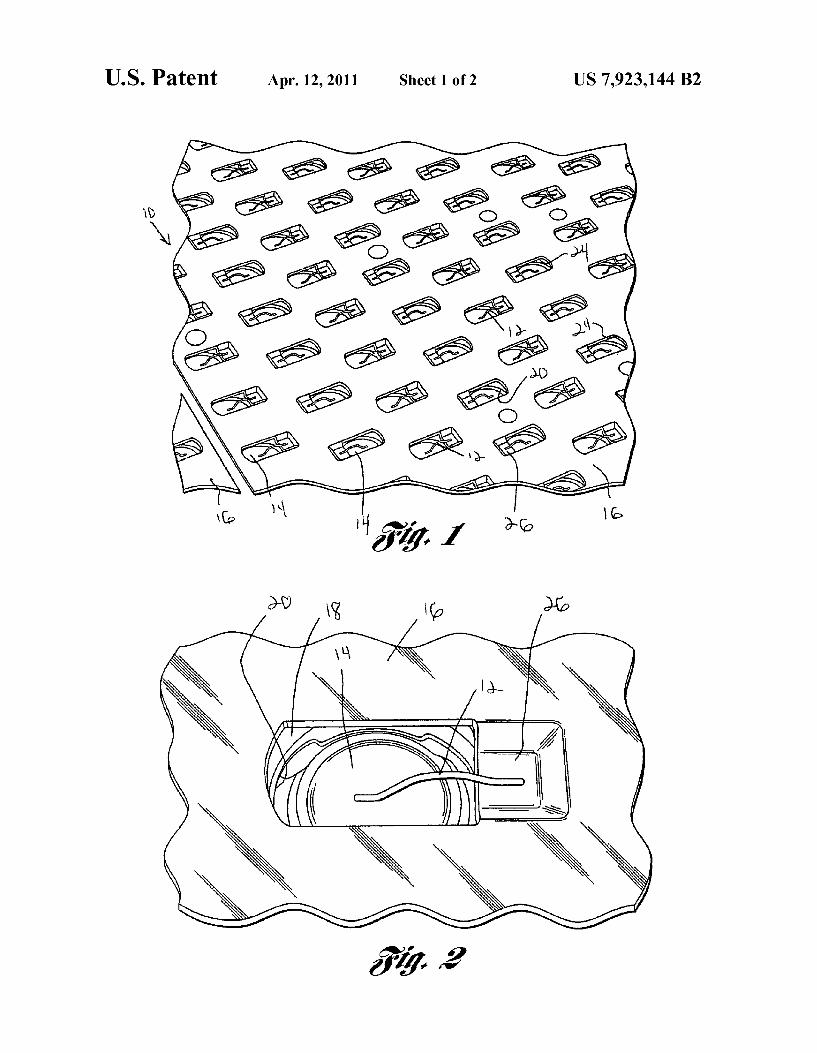
FIG. 1 shows a top view of a battery pack system according to the present invention.
FIG. 2 shows a top view of one battery cell connected to a collector plate via a conductor according to the present inven tion.
FIG.3 shows apartial cross sectional view of a battery pack system according to the present invention.
FIG. 4 shows a top view of a battery cell according to the present invention.
DESCRIPTION OF THE EMBODIMENT(S)
Referring to the drawings, a battery pack system 10 for use in an electric Vehicle or in other industrial equipment is shown. It should be noted that the battery pack system 10 shown in the drawings is for use in an electric Vehicle, how ever the battery pack system and battery cells may be used in any combination and in any design known for use in any number of industries including but not limited to any type of vehicle and any technology dealing with aerospace, marine, aviation, industrial equipment, and any other electrical sys tem that has a need for protecting emergency responders or everyday users from electrocution and other injuries due to high Voltage applications.
The battery pack system 10 has a tunable frangible con ductor/wire 12 arranged between a plurality of battery cells 14 and a collector plate 16. The use of the frangible battery pack conductor 12 will minimize the possibility of short circuiting and reduce potential exposure to high Voltages by emergency responders or others in contact with the electric vehicles and industrial equipment. The battery pack system 10 of the present invention may include connections involv
10
15
25
30
35
40
45
50
55
60
65
4 ing the battery cells 14 that will break at a predetermined impact and a predetermined thermal event. In one embodi ment of the present invention the collector plate 16 will be connected to a plurality of battery cells 14 by the use of a narrow and thin conductor 12 Such as a wire bond connection. It should be noted that the present invention may be designed such that the frangible conductor 12 is used within the battery pack system 10 to disconnect all of the battery cells 14 from some or all portions of the electrical circuits of the electric vehicle or to disconnect predetermined portions of the cir cuits from the battery cells 14. Furthermore, the wire conduc tor 12 may be mechanically and electrically tuned to prede termined specifications to fail before the circuit reaches a predetermined threshold of extremely high heat or extreme forces applied thereto such that the battery pack system 10 may be accessible to emergency responders or other users of the electric vehicle without the threat of electrocution or injury. It should be noted that the system 10 generally is designed for use in an electric Vehicle having a high Voltage electric system. It should be noted that any of these vehicles may be any of the known auto vehicles Such as passenger's vehicles, military vehicles, delivery vehicles and the like. Furthermore, the same technology has also been designed for use on aerospace, aviation, and marine sector vehicles and also industrial equipment that have any type of electric sys tem and power Supply. This technology may also be used in any other technologies such as but not limited to mining equipment, cranes, presses or the like. Therefore, the present invention of a frangible battery pack system 10 can be used with any known electric vehicle or electrical system indus trial, personal or otherwise.
FIGS. 1 through 4 show a tunable frangible battery pack system 10 according to the present invention. The battery pack system 10 includes a housing 18. The housing 18 is generally a two piece clamshell housing that has a plurality of orifices 20 therethrough. The orifices 20 are generally circular in shape, however any other shaped orifice may be used. The housing 18 has a plurality of counter bores 22 arranged on each piece thereof. Each of the counter bores 22 will be used to hold and arrange therein a battery cell 14. The orifices 20 are arranged at or near a centerpoint of the counterbore 22 of the housing 18. It should also be noted that it is contemplated to have a cooling tube arranged through the housing 18 to allow for cooling of the batteries 14 if need be. It should be noted that in one contemplated embodiment the housing 18 is made of a plastic material that is injected molded into the predetermined shape for the housing 18. However, it should be noted that any other type of material including metal, ceramic, composite, or natural material may be used for the housing 18 depending on the design requirements and envi ronment in which the battery pack system 10 will be used.
Arranged within each counter bore 22 of the housing 18 is a battery cell 14. The battery cells 14 generally have a cylin drical shape in the embodiment shown. However, any other shape battery cell 14 may be used depending on the design requirements. The battery cells 14 are arranged within the counterbore 22 such that both ends of the battery cells 14 are exposed via the orifices 20 located at each end of the counter bores 22 through the housing 18. The end of the battery cells 14 will be used for electrical connection between the battery cells 14 and the collector plate 16. The battery pack system 10 also includes a first collector
plate 16 arranged on one end of the housing 18 and a second collector plate 16 arranged on another end of the housing 18. In one contemplated embodiment a single collector plate 16 will be used to cover one side of the housing 18. However, it is also contemplated to use multiple differently shaped and

US 7,923,144 B2 5
sized collector plates 16 on one side of the housing 18 and/or multiple collector plates 16 of different size and shapes on the opposite side of the housing 18. The collector plate 16 may have the same shape as that of the housing 18 and the shape may be of any known shape or diameter Such as rectangular, triangular, Square, circular, or any other known shape. Gen erally, the collector plate 16 is made of a metal material. However, it should be noted that the collector plate 16 can be made of any known material such as composite, any known metal, ceramic, natural material, plastic or any other material capable of conducting electricity. In one embodiment con templated an electroless or electrolytic nickel plated alumi num or copper sheet metal will be used for the collector plates 16. The collector plates 16 will have a plurality of orifices 24 therethrough that will align with and mate with the orifices 20 through the housing 18 into the counter bores 22 of the hous ing 18. It should be noted that in one contemplated embodi ment the orifices 24 are generally rectangular in shape, how ever any other shaped orifice 24 Such as Square, circular, triangular, pentagonal or the like may be used depending on the design requirements and environment in which the battery pack system 10 will be used. The collector plate 16 is secured to the housing 18 via any known connecting methodology. In one contemplated embodiment a combination of heat staking and epoxy will be used to connect the collector plate 16 to the housing 18. It should be noted that the orientation of the battery cells 14 within the housing 18, i.e., positive side up or positive side down and the size and shape of the collector plates 16 will allow for different designs and will create a unique and efficient method for creating a combination of parallel and series connections for the battery cells 14 within the electrical system of the electric vehicle. This will allow for many different designs and parameters to be achieved because of the variety of orientation of battery cells 14 within the housing 18 and the size and shape of the collector plates 16 that may be used to create both parallel and series connec tions within the electrical system. Furthermore, the battery cells 14 may be mounted in any other known type of matrix as long as the matrix is clad by a bus bar, collector plate or conductive plate 16.
Arranged between the battery cells 14 and the collector plates 16 are a plurality of frangible conductors 12 that create the electrical connection therethrough. Generally, the fran gible conductor 12 is in the shape of a wire, however it is also contemplated to be in any other shape. Such as a ribbon or the like. The conductor 12 generally is bonded to an end surface of the battery cell 14 and to the collector plate 16 at a prede termined position. In the embodiment shown the collector plate 16 may include a recessed portion 26 adjacent to the orifice 24 of the collector plate 16 that exposes the end of the battery cell 14. The recessed area 26 may be of any predeter mined size and shape. In the embodiment shown the recessed area 26 is adjacent to each and every orifice 24 through the collector plate 16. The frangible conductor 12 may also have any type of cross
section other than a round or circular such as square, rectan gular, triangular, or any other known cross sectional shape. In one embodiment contemplated the conductor 12 is generally made of an aluminum alloy material. Some aluminum alloy materials that may be used include but are not limited to 99.999% aluminum, 99.99% aluminum, 99% aluminum and 1% silicone, or 99.5% aluminum. It should be noted that any other type of metal, ceramic or composite may also be used for the frangible conductor 12 according to the present inven tion. The frangible conductor 12 of the present invention may also include 0.5% by weight magnesium and 50 parts per million nickel along with the aluminums as described above.
10
15
25
30
35
40
45
50
55
60
65
6 The use of the magnesium will add strength to the wire 12 which may help bond through any Surface oxide that may be present on the battery cell 14 and collector plate 16. Further more, the nickel may provide a corrosion resistance effect to the frangible conductor 12 for the present invention. It should be noted that any other known Substance may also be added to the conductor 12 along with or in place of one or both of the magnesium or nickel material. It should be noted that the frangible conductor 12 of the present invention generally is in the shape of a round wire that may drawn into any known diameter, however in the embodiment shown the diameter may be anywhere between 0.011 inches to 0.016 inches. In particular one diameter may be 0.012 inches or 0.015 inches. Furthermore, it is also contemplated that the frangible con ductor 12 may be used in a ribbon form wherein the cross section of the ribbon may be within the range of 0.02 inches by 0.001 inches to 0.1 inches by 0.01 inches. In one contem plated embodiment a ribbon would have the form of 0.03 inches by 0.003 inches or 0.08 inches by 0.008 inches. The frangible conductor 12 is connected to the end of the
battery cell 14 and the collector plate 16 via any known connecting methodology both mechanical and chemical. The conductor 12 is bonded to the battery cell 14 and to the collector plate 16 in one contemplated embodiment via an ultrasonic wedge bonding process. However, it should be noted that any other ultrasonic bonding process along with any other type of welding process, mechanical crimping pro cess, conductive epoxy process, Soldering process, installa tion displacement connectors, or any other known bonding process may be used to connect the frangible conductor 12 to both the collector plate 16 and the battery cell 14. In the contemplated ultrasonic wedge bonding process a bonding machine will feed out the conductor 12 either in the form of wire, ribbon or any other shape at a predetermined pace and will have it bonded to both the battery cell substrate and the collector plate Substrate and cut the conductor 12 at an appro priate length. The ultrasonic wedge bonding process uses a computer controlled mechanism that can be programmed to place the wires 12 automatically and then use optical recog nition or other methodology to validate and adjust the posi tions of the conductor 12 with relation to the battery cells 14 and the collector plate 16.
It should be noted that aluminum has been chosen as the preferred material for the conductor wire 12 because it is easily tunable to be a frangible conductor 12 for the following reasons. It may be bonded using the ultrasonic process, it is a low cost element and it has high thermal conductivity and low electrical resistivity, which will increase the durability and tunability of the battery pack system 10 in the electric vehicle. It should be noted that high thermal conductivity will allow a Small cross section wire 12 to carry a current Sufficient enough to operate in the high Voltage applications. The Small cross section furthermore is strong enough to Support itself under normal operating conditions of the vehicle and battery pack system 10 but will not add significant strength to the battery pack system 10. This will ensure that the battery pack battery cells 14 will disconnect from the collector plate 16 when a predetermined mechanical force or thermal situation is applied to the battery pack system 10. It should be noted that the diameter, length and path of which the frangible conductor 12 is laid and arranged between the battery cell 14 and collector plate 16 can all be varied to allow for a prede termined fatigue and fracture to occurat predetermined vibra tion levels, mechanical force levels and thermal levels which exceed any predetermined battery pack system 10 limitations throughout the entire electrical vehicle operating system.

US 7,923,144 B2 7
It should be noted that it is contemplated to provide an added level of mechanical support within the battery pack system 10, an added level of corrosion resistance, and arc Suppression by use a silicone dielectric gel to fill the counter bore 22 around the battery cells 14 and cover the frangible conductor wire bond and wire 12. It should be noted that any other type of gel or other gel like Substance may be used to provide the extra mechanical Support, corrosion resistance and arc Suppression as that of a silicone dielectric gel.
In operation, the battery pack system 10 will operate within the electric vehicle or industrial equipment to prevent elec trocution and other injuries to first responders or users of such vehicle and equipment. In particular, in the event of an elec tric Vehicle collision, crash or excessive shock, there is a chance that components within the electrical vehicle and specifically the battery cells 14 within the battery pack system 14 could break in a manner which is hazardous to the occu pants of the vehicle, emergency responders, first responders, and any other people involved. In order to combat this poten tial injury situation the frangible conductor 12 is arranged between the battery cells 14 and collector plates 16 and is designed to break or disconnect the collector plate 16 from the battery cells 14 when a predetermined mechanical force is applied to the vehicle in the form of a shock, jolt or other excessive mechanical episode. It should be noted that the two primary hazards within the electric vehicle for which the frangible battery pack system 10 is best used are high Voltages and thermal runaway of the battery cells 14 within the battery pack system 10. It should be noted that for the battery pack system 10 to develop a short, the battery cell parts need to move relative to each other and come in contact with one another. The frangible conductor 12 will break during this relative motion so that if there is contact between the batteries 14, the battery cells 14 will already be disconnected from one another and there will be no short circuit therefrom. Under normal operating conditions of the electric vehicle
the high voltage is created by the battery cells 14 are isolated from the occupants and emergency responders. In many fail ure modes the safety systems of the electric vehicle operating system further isolate the high voltages but in the most severe collisions, the high Voltages may become accessible. There fore, the frangible conductors 12 will help reduce the poten tial of electrocution and any electrical danger by disconnect ing the battery cells 14 from the electrical vehicle car system and improve the abuse tolerance of the battery pack system 10. Hence, with the frangible conductors 12 made of, in one contemplated embodiment, aluminum wires from very spe cific alloys that are ultrasonically bonded to the battery cells 14 and to a collector plate 16 the ability to design and adjust the size, length, diameter, and specific materials added to the alloys of the frangible conductors 12 will allow for a variety of breaking points for the frangible conductor 12 tuned to specific mechanical forces encountered in electric Vehicles such that a small five mile per hour bumper collision will not break the frangible conductors 12, however, higher force collisions, both front, rear and side and/or rollovers of an electric vehicle will allow for breaking and disconnecting of the battery cells 14 from the collector plate 16 and hence, the removal of short circuits and possible electrocution by first responders. However, the conductors 12 as designed will still provide adequate current carrying capability and mechanical strength during normal operations of the electrical vehicle.
Therefore, the present invention will allow for the mechanical, thermal and electrical behavior of the frangible conductor 12, in this case in the form of a wire, to be cali brated to predetermined values of any known electrical val ues, mechanical values and thermal values based on the
10
15
25
30
35
40
45
50
55
60
65
8 design requirements and the environment in which the elec trical vehicle or equipment will be used. Therefore, if mechanical, electrical and thermal scenarios beyond the designed operating conditions of the battery pack system 10 are encountered the conductors 12 will disconnect by some type of mechanical or thermal means. These thermal means may include but are not limited to an over current, runaway combustion products, runaway heating, electrical arcing, reversal of battery cell Voltage and high impedance connec tions. Examples of Such mechanical means or occurrences through which the frangible conductors 12 may disconnect may include but are not limited to cyclic loading and fatigue, ultimate tensile strength and bonding failure in the interface between the battery cells 14 and the collector plates 16. Hence, the tunable frangible battery pack system 10 is capable of being designed for any known electric Vehicle application and will provide piece of mind and safety to first responders responding to accidents involving electric vehicles that have high voltage battery packs from fear of electrocution and other injuries during rescue of occupants within the electric vehicles during Such situations. The present invention has been described in an illustrative
manner. It is to be understood that the terminology which has been used is intended to be in the nature of words of descrip tion rather than of limitation. Many modifications and variations of the present invention
are possible in light of the above teachings. Therefore, within the scope of the appended claims, the present invention may be practiced otherwise than as specifically described. What is claimed is: 1. A battery pack system, said battery pack system com
prising: a plurality of battery cells; a battery pack housing comprised of a first housing mem
ber and a second housing member piece complementary to said first housing member, wherein an internal region defined by a first housing member internal Surface and a second housing member internal Surface is configured to hold said plurality of battery cells, wherein said first housing member internal Surface further comprises a first plurality of counterbores configured to hold a first end portion of said plurality of battery cells, wherein said first housing member internal Surface further com prises a first plurality of orifices corresponding to said first plurality of counterbores and coupling said first housing member internal Surface to a first housing mem ber external Surface, wherein said second housing mem ber internal Surface further comprises a second plurality of counterbores configured to hold a second end portion of said plurality of battery cells, wherein said second housing member internal Surface further comprises a second plurality of orifices corresponding to said second plurality of counterbores and coupling said secondhous ing member internal Surface to a second housing mem ber external surface;
at least one first housing member collector plate arranged on said first housing member external Surface, wherein said at least one first housing member collector plate further comprises a third plurality of orifices aligned with said first plurality of orifices, wherein said at least one first housing member collector plate is electrically conductive;
at least one second housing member collector plate arranged on said second housing member external Sur face, wherein said at least one second housing member collector plate further comprises a fourth plurality of orifices aligned with said second plurality of orifices,

US 7,923,144 B2 9
wherein said at least one second housing member col lector plate is electrically conductive;
a first plurality of frangible conductors electrically con necting said at least one first housing member collector plate and each of said plurality of battery cells, wherein 5 said first plurality of frangible conductors are electri cally connected to each of said plurality of battery cells via a first terminal corresponding to each first end por tion of said plurality of battery cells; and
a second plurality of frangible conductors electrically con necting said at least one second housing member collec tor plate and each of said plurality of battery cells, wherein said second plurality of frangible conductors are electrically connected to each of said plurality of battery cells via a second terminal corresponding to each second end portion of said plurality of battery cells.
2. The battery pack system of claim 1 wherein said first and second housing members are made of a plastic material.
3. The battery pack system of claim 1 wherein said at least one first housing member collector plate and said at least one second housing member collector plate are comprised of a material selected from the group consisting of nickel plated aluminum and copper.
4. The battery pack system of claim 1 wherein said first and second pluralities of frangible conductors are configured to break when the battery pack is exposed to a predetermined force or heat.
5. The battery pack system of claim 1 wherein said first and second pluralities of frangible conductors are comprised of an aluminum alloy.
6. The battery pack system of claim 5 wherein said alumi num alloy has a predetermined percentage, by weight, of magnesium and nickel.
7. The battery pack system of claim 6 wherein said mag nesium is approximately 0.5% by weight of said aluminum alloy and said nickel constitutes approximately 50 parts per million of said aluminum alloy.
10
25
30
35
10 8. The battery pack system of claim 1 wherein said first
plurality of frangible conductors are bonded to each of said plurality of battery cells and said at least one first housing member collector plate, and wherein said second plurality of frangible conductors are bonded to each of said plurality of battery cells and said at least one second housing member collector plate.
9. The battery pack system of claim 1 wherein said first plurality of frangible conductors are ultrasonically bonded to each of said plurality of battery cells and said at least one first housing member collector plate, and wherein said second plurality of frangible conductors are ultrasonically bonded to each of said plurality of battery cells and said at least one second housing member collector plate.
10. The battery pack system of claim 1 wherein said first and second pluralities of frangible conductors have a circular cross section or ribbon like shape.
11. The battery pack system of claim 1 further comprising a silicone dielectric gel arranged around said plurality of battery cells.
12. The battery pack system of claim 1 wherein said at least one first housing member collector plate is secured to said first housing member external Surface by heat staking or epoxy, wherein said at least one second housing member collector plate is secured to said second housing member external Surface by heat staking or epoxy, said at least one first housing member collector plate further comprising a first plurality of recessed areas adjacent to said third plurality of orifices in said at least one first housing member collector plate, said first plurality of frangible conductors electrically connected to said first plurality of recessed areas, said at least one second housing member collector plate further compris ing a second plurality of recessed areas adjacent to said fourth plurality of orifices in said at least one second housing mem ber collector plate, said second plurality of frangible conduc tors electrically connected to said second plurality of recessed aaS.