Autorizada la entrega del proyecto EL DIRECTOR DEL ... · plantilla, se ha creado la cinemática de...
114
Proyecto realizado por el alumno: Enrique García Ruiz Fdo.: …………………… Fecha: ……/ ……/ …… Autorizada la entrega del proyecto EL DIRECTOR DEL PROYECTO Petter Falkman Fdo.: …………………… Fecha: ……/ ……/ …… Vº Bº del Coordinador de Proyectos Álvaro Sánchez Miralles Fdo.: …………………… Fecha: ……/ ……/ ……
Transcript of Autorizada la entrega del proyecto EL DIRECTOR DEL ... · plantilla, se ha creado la cinemática de...

Proyecto realizado por el alumno:
Enrique García Ruiz
Fdo.: …………………… Fecha: ……/ ……/ ……
Autorizada la entrega del proyecto
EL DIRECTOR DEL PROYECTO
Petter Falkman
Fdo.: …………………… Fecha: ……/ ……/ ……
Vº Bº del Coordinador de Proyectos
Álvaro Sánchez Miralles
Fdo.: …………………… Fecha: ……/ ……/ ……

ESCUELA TÉCNICA SUPERIOR DE INGENIERÍA I.C.A.I.
TÍTULO DE: INGENIERO INDUSTRIAL
VIRTUAL PREPARATION OF AUTOMATION STATION OF VOLVO TRUCKS© PRODUCTION
STATION USING DELMIA© SOLUTIONS
Autor: Enrique García RuizDirector: Petter Falkman
Madrid Septiembre 2010

VIRTUAL PREPARATION OF AUTOMATION STATION OF VOLVO TRUCKS© PRODUCTION STATION USING DELMIA© SOLUTIONS. Autor: García Ruiz, Enrique.
Director: Falkman, Petter.
Entidades colaboradoras: Volvo Trucks Company.
Chalmers University of Göteborg.
RESUMEN DEL PROYECTO:
La simulación y fabricación virtual es cada vez más prometedora tanto en la industria del automóvil como en las demás industrias manufactureras. La constante innovación en los sectores de fabricación permite a los fabricantes producir en menor tiempo y reduciendo costes. Las herramientas digitales de fabricación como Dassault Systèmes, DELMIA V5 han sido desarrolladas hasta tal punto, que prestan apoyo a casi todo tipo de fabricación en lo que respecta a sus tres pasos principales, que son; el diseño, la planificación de la producción y la puesta en marcha virtual.
Este trabajo forma parte de “FFI Research Project”, una investigación realizada en Suecia entre el gobierno y la industria automotriz con el fin de alcanzar objetivos sociales como la reducción del impacto medioambiental del transporte y el fortalecimiento de la seguridad vial en el país. En esta investigación intervienen empresas por el gobierno como VINNOVA (la Agencia gubernamental sueca de Sistemas de Innovación, la administración de Carreteras de Suecia y la Agencia Sueca de Energía y por la industria como Volvo AB, AB Volvo Cars, Scania CV AB, Saab AB de Automóviles y FKG.
El proyecto expone las orientaciones necesarias para la construcción de la automatización de una estación virtual utilizando las soluciones que ofrece Dassault Systèmes (Delmia, DELMIA Automation). La memoria recoge cómo el comportamiento de los equipos se puede definir utilizando piezas CAD con el fin de reducir al mínimo, o idealmente por completo, el trabajo de posteriores ingenieros. Por lo tanto, es necesario investigar cómo esta información definida puede ser reutilizada.
En esta memoria se crea y se simula una estación contenida en una línea existente de producción de cabinas de camiones en “Volvo Trucks Umeå”, situada en el norte de Suecia, adecuando el trabajo a la normativa de Volvo. La estación se basa en el montaje de la cabina de un camión una vez que han sido fabricadas las distintas partes de esta, mediante el uso de cuatro robots y sus correspondientes herramientas.

Ilustración 1. Modelo virtual de la estación Y.
En primer lugar, se ha utilizado la geometría existente en CAD de Volvo para crear una plantilla en el entorno PPR (Producto, Proceso y Recurso). Una vez creada esa plantilla, se ha creado la cinemática de la misma utilizando CATIA, debido a que Volvo carece de la herramienta de DELMIA capaz de alcanzar este fin. Para ello, se ha tenido que separar cada pieza en partes más pequeñas y crear los diferentes mecanismos con el fin de darle movilidad (cinemática) a las piezas rígidas proporcionadas por Volvo.
Tras definir la cinemática, el siguiente paso en este proyecto ha sido la creación de las etiquetas y las tareas de los robots, que se ha basado en la visita a la estación de Volvo Trucks en Umeå, Suecia. Las principales tareas que se definen son los diferentes movimientos que realiza el robot para montar y desmontar herramientas o coger, soltar y soldar piezas, todo ello optimizando el tiempo del proceso. Posteriormente, se creó la SOP (secuencia de operaciones), validándola y optimizándola mediante el uso de los programas “Sequence Planner” y “Supremica”.
Por último, se ha utilizado el módulo de DELMIA dedicado a automatización (DELMIA automation) para definir la lógica interna basada en las tareas anteriormente creadas. Se ha creado el comportamiento lógico utilizando un diagrama de funciones secuencial (SFC) compuesto por bloques de acciones y transiciones (condiciones). Para controlar este comportamiento se ha diseñado virtualmente un HMI (interfaz entre

humanos y máquinas) y se ha relacionado mediante el uso de puertos en las distintas piezas (robots, agarraderas, pistolas de soldar…).
El informe está escrito de tal manera que ayude a los lectores a comprender todos y cada uno de los pasos que se han dado durante el proyecto. Viene complementado con figuras, bibliografía, páginas consultadas y programas empleados.
La conclusión principal es, como se demuestra, que es posible controlar el campo de trabajo de la estación Y, para el montaje de cabinas de camiones, con un PLC virtual a través de un HMI. Para ello, se ha utilizado la base de datos de Volvo Trucks y las soluciones que ofrece el programa DELMIA a través de la simulación de la estación de trabajo.
Este trabajo realizado con Volvo podría reutilizarse en otras compañías para simular otras estaciones de producción. Se adjunta en la memoria, en uno de los apéndices, unas guías de trabajo con el fin de esquematizar, a modo de tutorial, los diferentes pasos a seguir para lograr automatizar las estaciones virtualmente utilizando DELMIA.

ABSTRACT
Simulation and virtual manufacturing is becoming more and more promising in the automotive industry and in the other manufacturing industries. Constant innovation in the manufacturing sectors allows the manufacturers to produce products reducing cost and time. Digital manufacturing tools like Dassault Systèmes DELMIA V5 platform have been developed to such an extent that provide support to almost all kind of manufacturing industries regarding design, production planning and virtual commissioning, the three major steps with in digital manufacturing.
This work is a part of “FFI Research Project”, an investigation that is being carried out in Sweden between the government and the automotive industry in order to satisfy social goals such as reducing the environmental impact of transport and strengthening the traffic security. Very important companies participate on this research. On one hand, government industries such as VINNOVA (the Swedish Governmental Agency for Innovation Systems), the Swedish Road administration and the Swedish Energy Agency and on the other hand, automotive industries such as Volvo AB, Volvo Cars AB, Scania CV AB, Saab Automobile AB and FKG.
This thesis work highlights the necessary guidelines to build a virtual Automation station using Dassault Systèmes solutions (Delmia, Delmia Automation). The report clarifies how equipment behavior can be defined on CAD parts that will minimize, or ideally diminish entirely, the need of rework for the subsequent engineer. The other way of looking at this problem, demands to investigate how the defined information can be reused.
A station within an existing front cab production line at “Volvo Trucks Umeå”, in the north of Sweden, is created virtually and simulated, following the Volvo normative. The station is focused on the assembly of the truck cab after the different parts are made by using four robots and their tools.

Figure 1. Virtual model of Station Y
First of all, the existing CAD geometry from Volvo was used to build a template in PPR hub. Once the template was created, the kinematics were defined using CATIA, due to Volvo does not have DELMIA tools to lead this aim. It was necessary to separate each piece in smaller parts and to define the different joints in order to create the kinematics in the rigid pieces that Volvo had.
Once the kinematics were defined, the next step in the report was to define the tags and tasks of the robots. This activity was based on the visit to Volvo Truck Station at Umeå, Sweden. The main tasks defined are the different movements that the robot does like mount and dismount the tools or to pick, drop and weld the pieces, all of them optimizing the cycle time. Later, the SOP (sequence of operations) was created. It was optimized and validated using “Sequence Planner” and “Supremica” programs.
Finally, DELMIA automation was used to define the internal logic that was based on the tasks that were previously created. The logical behavior was created using the sequential function char (SFC) that is described by actions (blocks) and transitions (conditions). In order to control this behavior, a virtual HMI (Human-Machine Interface) was defined and it was related by using ports in the different pieces (robots, grippers, weld guns…).

The report has been written in a way that helps the reader to understand each of the steps that have been done during the work. It is complemented with figures, bibliography, consulted pages and the programs that have been used.
The main conclusion is, as it has been demonstrated, that it is possible to control the work cell of the Station Y to do the assembly of the truck cabs. It is controlled by a virtual PLC through an HMI using DELMIA solutions and the Volvo Trucks database system.
This work has been done with Volvo Company, although it could be reused in other companies to simulate other manufacturing stations. One of the appendices of the report includes a work guide that explains the different steps that are necessary to follow in order to lead the virtual automation station using DELMIA.

INDEX OF THE REPORT
9
UNIVERSIDAD PONTIFICIA COMILLAS
ESCUELA TÉCNICA SUPERIOR DE INGENIERÍA (ICAI) INGENIERO INDUSTRIAL
Index of the report
Chapter 1. Introduction .................................................................................. 15
Chapter 2. Preliminaries................................................................................. 16
2.1 Intended readers ............................................................................................ 16
2.2 Background .................................................................................................... 16
2.3 Problem description ...................................................................................... 17
2.4 Purpose & aims .............................................................................................. 18
2.5 Limitations ..................................................................................................... 19
2.6 Volvo Truck Corporation ............................................................................. 20
2.7 Dassault Systèmes .......................................................................................... 22
2.8 DELMIA V5R19 ............................................................................................ 22
2.8.1 Device Builder ........................................................................................................ 23
2.8.2 DELMIA Automation ............................................................................................. 24
2.8.3 HMI Control Panel Design ..................................................................................... 24
2.8.4 LCM Studio ............................................................................................................ 25
2.8.5 Smart Device Builder ............................................................................................. 25
2.8.6 Controlled System Simulator .................................................................................. 26
2.8.7 PLC Setup ............................................................................................................... 26
2.9 CATIA V5R19 ............................................................................................... 28
2.9.1 Volvo’s Requirements Specification towards Suppliers ......................................... 28
2.9.2 Different extensions files ........................................................................................ 29
2.10 Supremica....................................................................................................... 30
2.11 Sequence Planner .......................................................................................... 31
2.12 PLC ................................................................................................................. 32
2.12.1 About PLC’s ...................................................................................................... 32
2.12.2 IEC1131-3 .......................................................................................................... 34
2.12.3 Common Elements ............................................................................................. 35
2.12.4 Programming Languages ................................................................................... 36

INDEX OF THE REPORT
10
UNIVERSIDAD PONTIFICIA COMILLAS
ESCUELA TÉCNICA SUPERIOR DE INGENIERÍA (ICAI) INGENIERO INDUSTRIAL
2.13 FFI Research Project .................................................................................... 42
Chapter 3. Analysis of the Task ...................................................................... 44
3.1 The station ...................................................................................................... 44
3.2 Manufacturing Hub ...................................................................................... 54
3.3 Learning the Manufacturing Hub ............................................................... 58
3.3.1 DPM (Digital Process Manufacturing)-Process Engineer Compatibility ............... 58
3.3.2 How to Make Template in DELMIA Process Engineer ......................................... 58
3.3.3 Selecting a Project from the Manufacturing Hub ................................................... 61
3.4 How to populate Product List ...................................................................... 64
3.5 Assign Robot Units to Activities ................................................................... 64
3.6 Load fasteners in Delmia from ENOVIA .................................................... 65
3.7 Assign Fasteners to Resources ...................................................................... 65
3.8 Defining I/O Signals ...................................................................................... 66
3.9 DELMIA Automation ................................................................................... 66
3.9.1 SFC codes ............................................................................................................... 66
3.9.2 HMI ........................................................................................................................ 66
3.9.3 PLC ......................................................................................................................... 67
3.10 Sequence of Operations (SOP) ..................................................................... 67
Chapter 4. Methodology ................................................................................. 69
Chapter 5. Results ........................................................................................... 71
5.1 Creating the work cell ................................................................................... 71
5.2 Planning the SOP ........................................................................................... 72
5.3 Kinematics ...................................................................................................... 72
5.4 Small WorkCell example .............................................................................. 73
5.4.1 Define Kinematics .................................................................................................. 74
5.4.2 Create Robot Tags & Tasks .................................................................................... 74
5.4.3 Create Logic, HMI & Control Panel ....................................................................... 74
5.5 Final simulation ............................................................................................. 76
5.5.1 Defining the template ............................................................................................. 77

INDEX OF THE REPORT
11
UNIVERSIDAD PONTIFICIA COMILLAS
ESCUELA TÉCNICA SUPERIOR DE INGENIERÍA (ICAI) INGENIERO INDUSTRIAL
5.5.2 Defining Kinematics ............................................................................................... 77
5.5.3 Create Robot Tags & Tasks .................................................................................... 83
5.5.4 Create Logic, HMI & Control Panel ....................................................................... 84
5.6 Bridge Gaps.................................................................................................... 91
Chapter 6. Conclusions................................................................................... 94
Chapter 7. Future work .................................................................................. 96
Chapter 8. Bibliography ................................................................................. 97
Chapter 9. List of Abbreviations ..................................................................... 99
Chapter 10. Appendices .................................................................................. 101
10.1 Appendix A .................................................................................................. 101
10.1.1 BUILD LAYOUT (Robot Unit) ...................................................................... 101
10.1.2 Moves to .cgr files ............................................................................................ 102
10.1.3 Task definition ................................................................................................. 103
10.1.4 Internal Logic and HMI ................................................................................... 105
10.1.5 Delmia Automation LCM Studio ..................................................................... 107
10.2 Appendix B ................................................................................................... 113

Introduction
12
UNIVERSIDAD PONTIFICIA COMILLAS
ESCUELA TÉCNICA SUPERIOR DE INGENIERÍA (ICAI) INGENIERO INDUSTRIAL
Index of the figures
Figure 1. Collaborative Manufacturing Management Model(4) ........................... 22
Figure 2. Tools availables to design the virrtual HMI .......................................... 25
Figure 3. Simulation with PLC(7) ......................................................................... 27
Figure 4. Things not allowed by Volvo ................................................................. 29
Figure 5. Supremica Interface ............................................................................... 30
Figure 6. Sequence Planner Interface .................................................................... 32
Figure 7. Two parts of the standard IEC 1131-3 ................................................... 34
Figure 8. Sequential Functional Charts (SFC) (8) ................................................. 37
Figure 9. Example of Ladder Diagram (8) ............................................................ 38
Figure 10. Example of Instruction List (8) ............................................................ 39
Figure 11. Example of Functional Block Diagram (8) .......................................... 39
Figure 12. Example of Structured Text (8) ........................................................... 40
Figure 13. FFI project(17) ..................................................................................... 42
Figure 14. Station X .............................................................................................. 45
Figure 15. Description of station Y ...................................................................... 45
Figure 16. Robot A with the side left going to fixture .......................................... 47
Figure 17. Robot A and its tools ............................................................................ 47
Figure 18. Robot D and its tools ............................................................................ 48
Figure 19. Robot B ................................................................................................ 49
Figure 20. From above the assembly of the flow cab ........................................... 50
Figure 21. Robot C ................................................................................................ 50
Figure 22. Robot C spot welding in a low cab ...................................................... 52
Figure 23. Fixture .................................................................................................. 53
Figure 24. Fixture with the cabin in it………….……………………………….. 53

Introduction
13
UNIVERSIDAD PONTIFICIA COMILLAS
ESCUELA TÉCNICA SUPERIOR DE INGENIERÍA (ICAI) INGENIERO INDUSTRIAL
Figure 25.Empty fixture ........................................................................................ 53
Figure 26. Station Y .............................................................................................. 54
Figure 27. Delmia PPR (20) .................................................................................. 55
figure 28. Mainly views ......................................................................................... 56
figure 29. Resource List ........................................................................................ 57
Figure 30. Manufacturing Hub Menu bar (1) ........................................................ 58
Figure 31. Template opened in Delmia V5 ........................................................... 60
Figure 32. Vitual model of Station Y .................................................................... 61
Figure 33. Process Engineer Dialogue box(1) ....................................................... 62
Figure 34. Open Project Dialogue box(1) ............................................................. 63
Figure 35. Working with Supremica ..................................................................... 67
Figure 36. Verification of SOP using Supremica .................................................. 68
Figure 37. Methodology of the Final Term Project ............................................... 69
Figure 38. SOP for Station Y ................................................................................ 72
Figure 39. Small workcell (File based System) .................................................... 73
Figure 40. SFC code of the small workcell ........................................................... 75
Figure 41. HMI in the small workcell example ..................................................... 76
Figure 42. Geogripper where it has needed define kinematics ............................. 78
Figure 43. Complete clamp opened in a new window .......................................... 79
Figure 44. The part of the clamp when it necessary to define the revolute joint .. 79
Figure 45. Part with revolute joint inside the clamp ............................................. 80
Figure 46. Fix part inside the clamp ...................................................................... 80
Figure 47. Making rigid joints with the pink part to move all together ................ 81
Figure 48. Making the simulation to verificate the behaviur of one complete
clamp ..................................................................................................................... 82
Figure 49. Geogripper after define the kinematics in clamps ............................... 83
Figure 50. In fixture have been defined the kinematics in clamps ........................ 83

Introduction
14
UNIVERSIDAD PONTIFICIA COMILLAS
ESCUELA TÉCNICA SUPERIOR DE INGENIERÍA (ICAI) INGENIERO INDUSTRIAL
Figure 51. Creating Tags & Tasks ......................................................................... 84
Figure 52. Sequence of Robot A by using Sequence Planner ............................... 85
Figure 53. Non blocking in Supremica software ................................................... 86
Figure 54. GRAFCET of robot A unit .................................................................. 87
Figure 55. Defining ports ...................................................................................... 88
Figure 56. SFC code of robot unit A ..................................................................... 88
Figure 57. Simulating the SFC code in DELMIA ................................................. 89
Figure 58. Connecting Ports .................................................................................. 90
Figure 59. Control of Work cell vitual PLC through HMI ................................... 91
Figure 60. Process Simulation Menu bar(1) ........................................................ 104
Figure 61. Workbenches in LCM ........................................................................ 107
Figure 62. Creating blocks .................................................................................. 108
Figure 63. Interface Block Manager .................................................................... 108
Figure 64. Behavior of the program visible n SFC+ view .................................. 110
Figure 65. Pre-defined gadgets ............................................................................ 110
Figure 66. 2 values: closed and opened ............................................................... 111
Figure 67. Signal Monitoring, testing its behavior .............................................. 111
Figure 68. Sequence for Robot C ........................................................................ 113
Figure 69.Sequence for robots unit A,B and D ................................................... 114
Figure 70. Sequence for fixture and conveyor .................................................... 114

Introduction
15
UNIVERSIDAD PONTIFICIA COMILLAS
ESCUELA TÉCNICA SUPERIOR DE INGENIERÍA (ICAI) INGENIERO INDUSTRIAL
Chapter 1. INTRODUCTION
A new paradigm of manufacturing has been a new tide of change towards digital
manufacturing from quite some time now. Manufacturing across all industrial
sectors is being driven by a new set of business imperatives. Flexibility, nimble
response to capricious markets and lead time are few of the challenges facing
manufacturers. Constant innovation in the manufacturing sectors allows the
manufacturers to produce products with reduced cost and time. Similarly,
reducing the ramp up time while optimizing manufacturing processes has become
more significant as product lifecycle become shorter, the level of flexibility
increases, market prices erode and out-sourcing increases.
This Final Term Project aims at the virtual preparation of Automation Station at
Volvo Trucks Corporation using the DELMIA Solutions. This work can be seen
as the basic building block for the guide for the future Automation Stations. The
clear guide lines for the design and control engineer should be highlighted so that
no one does less or more work and more importantly rework should be avoided.
The effort is to make it possible for both the design engineer to define the
equipment as much as he can using CATIA and that the control or the process
engineer does not have to rework the same things which already been done by the
design engineer in CATIA.
This research work addresses the following questions:
Is it possible to create simulation model of a robot station following
Resource Centric approach of Volvo PTS using DELMIA Solutions?
How much information can be reused working with Manufacturing Hub?
Is it possible to control a virtual work cell from HMI connected with the
virtual PLC?

Preliminaries
16
UNIVERSIDAD PONTIFICIA COMILLAS
ESCUELA TÉCNICA SUPERIOR DE INGENIERÍA (ICAI) INGENIERO INDUSTRIAL
Chapter 2. PRELIMINARIES
2.1 INTENDED READERS
The report is informative and useful for the students from under graduate level to
the advance level like doctoral. The basic knowledge in digital logic control,
discrete event systems, CAD software & robot programming and manufacturing
assembly will be useful to fully grasp the contents of this report.
However, due to the amount of knowledge written it is not necessary to
understand the overall concept that is achieved in this report.
2.2 BACKGROUND
To prepare an automatic production system based on product variables and the
activities necessary for full compliance with product specifications of each and
every product variant require many different tasks. These activities cover all the
way from initial system design to final preparation of the functions of control for
equipment such as robots, turntables, weld guns, fixtures, etc. These activities
involve mapping product requirements to a system of production, i.e. specifying
the necessary operations to be executed in order to meet the specification. Based
on these necessary operations the next step is to find available equipment that can
perform them.
The additional requirements like to prepare the system of production cycle time,
the prevention of collisions or the sequence of operations should be taken care of.
Cycle time is an important requirement, not only because it should be short but it
should be the same as the rest of the systems so that a balanced flow through the

Preliminaries
17
UNIVERSIDAD PONTIFICIA COMILLAS
ESCUELA TÉCNICA SUPERIOR DE INGENIERÍA (ICAI) INGENIERO INDUSTRIAL
entire manufacturing plant is achieved. Many factors influence the final cycle time
and these factors have to be dealt with. Collision prevention deals with the
equipment movements within the system. It has to be prepared so that collisions
are avoided between equipment and product within the system. Reachability
means that all equipment reaches the designated area where operations are to be
executed. To find the best operation sequence is of great importance. To design an
optimal operation sequence many aspects have to be considered, such as product
requirements cycle time, potential collisions, reachability, etc.
Conventionally, these activities have been carried out by using different types of
software’s and by different people. Information has not necessarily been reused
between the different preparation phases. This means that information about the
prepared system has to be manually translated between different activities and
software’s which can lead to manual errors being incurred. Another important
factor is that not all necessary information has been created and therefore
influenced the final result. This has been especially true when it comes to the
logic behavior of the system, i.e. the control programs that supervise and direct
the overall flow in the production system as well as controlling the specific
equipment behavior.
2.3 PROBLEM DESCRIPTION
In order to meet the demands of the new manufacturing standards, manufacturers
have to adapt the ways which provide them with better tolerances and shorter lead
times. Digital manufacturing tools like Dassault Systèmes DELMIA V5 platform
have been developed to such an extent that provide support to almost all kind of
manufacturing industry regarding design, production planning and virtual
commissioning, the three major steps with in digital manufacturing.
Manufacturing organizations are taking those software´s more seriously to invest
in which the information among the different activities towards the digital

Preliminaries
18
UNIVERSIDAD PONTIFICIA COMILLAS
ESCUELA TÉCNICA SUPERIOR DE INGENIERÍA (ICAI) INGENIERO INDUSTRIAL
manufacturing can easily be transferred, read and reuse. This leads to a more
efficient cooperation possibilities.
One problem has been that information cannot be reused from one activity to
another or in other words one software to another. This problem can sometimes be
solved by specifying information in certain ways. This work aims at investigating
how information behavior can be defined on equipment in CAD system i.e.
CATIA and how this can be read into DELMIA from CATIA and be reused. This
research will help Volvo Trucks Corporation to have a clear and better defined
requirement specification towards their suppliers, supplying CAD (.CADPART,
.CADPRODUCT) parts.
A lot of time has been spent on creating virtual models. The ability to define
equipment behavior, e.g. turntables, fixtures, in order to reuse this information for
generation of control functions would decrease the amount of work in the
implementing phases.
The control programs thus generated will be tested to control the simulation
model. The PLC code from the control functions will be evaluated and verified
against the virtual controller by using the DELMIA Automation. It is very
necessary to investigate if the original model needs to be changed.
2.4 PURPOSE & AIMS
The automotive industry in the world today has tons of hundreds of suppliers for
each part or number of parts. The customer, for sure requires the highest possible
degree of satisfaction along with the flexibility delivered to them from their
suppliers. The standards are set by the giants within the industry and the suppliers
have to follow them in order to qualify as their suppliers. This work therefore has
been an effort to help VOLVO TRUCKS to define in a better way what they
require from their design suppliers and what they can offer to their process or
control engineer.

Preliminaries
19
UNIVERSIDAD PONTIFICIA COMILLAS
ESCUELA TÉCNICA SUPERIOR DE INGENIERÍA (ICAI) INGENIERO INDUSTRIAL
The purpose and objectives involved in this research work can be outlined as
follows.
Learn how to use Dassault Systèmes framework eg. CATIA, DELMIA Learn how to use PPR hub from DELMIA How should behavior be defined on equipment in CAD system i.e. CATIA
(-I/0´s) How can equipment behavior, I/0´s be read into DELMIA from CATIA
and be reused Investigate how specification of equipment behavior could be used for
generating control functions Perform a simulation of work cell sequence, robot paths, equipment
behavior based on specified equipment behavior Make for the report a way to increase the knowledge of how to use
DELMIA PPR structure
2.5 LIMITATIONS
First of all, there is a feeling that a clear guide line on using the software
(DELMIA, DELMIA AUTOMATION & DELMIA PROCESS ENGINEER)
lacks on the internet. For this reason it has been tried to comprehend this report as
a guide for the new students and the researchers to minimize their effort seeking
how they work and what the connections are among them.
Few basics starting guide lines are attached in appendix A.
One limitation was the time that was lost due to delays during information transfer
among the different segments of the project (Volvo, DELMIA, Chalmers and us).
It was very difficult to import the necessary working files in the beginning from
Volvo to Chalmers as Chalmers does not have the license of Manufacturing Hub
from DELMIA. Later the problem was to export the work from Volvo to
Chalmers. Also the frequent crashes of DELMIA and CATIA and time it took to
open the workcell added up in the time delays.

Preliminaries
20
UNIVERSIDAD PONTIFICIA COMILLAS
ESCUELA TÉCNICA SUPERIOR DE INGENIERÍA (ICAI) INGENIERO INDUSTRIAL
2.6 VOLVO TRUCK CORPORATION
Volvo is one of the world´s leading manufacturers of heavy commercial vehicles
and diesel engines and is founded in 1927.
The Volvo Group also offers a comprehensive range of customized solutions in
financing, leasing, insurance and service, as well as complete transport systems
for urban traffic.
The business areas are - Volvo Trucks, Mack, Renault Trucks, Volvo Buses,
Volvo Construction Equipment, Volvo Penta, Volvo Aero and Volvo Financial
Services. Several business units provide additional manufacturing development or
logistical support. The largest business units are: Volvo Powertrain, Volvo 3P,
Volvo IT, Volvo Logistics and Volvo Parts.
The Volvo Truck Corporation is the second-largest heavy-duty truck brand in the
world; more than 95% of the trucks that have been built are in the heavy weight
class above 16 tonnes. The Volvo trucks are sold and serviced in more than 140
countries all over the world.
The company's retail strategy is based on customer orientation and it is supported
by over 2300 dealerships and workshops. The trucks are the core products in the
total offer, which also includes aftermarket, service and extended offers.
Volvo Trucks has a production structure based on global presence. Volvo has
eight wholly-owned assembly plants and nine factories owned by local interests.
About 95% of the company's production capacity is located in Sweden, Belgium,
Brazil and the USA.
Throughout the production apparatus and the entire organization Volvo has
focused on its core values: Quality, Safety and Care for the Environment. With
17,000 dedicated employees, Volvo Trucks strives to have satisfied customers and
to be an attractive employer (2).

Preliminaries
21
UNIVERSIDAD PONTIFICIA COMILLAS
ESCUELA TÉCNICA SUPERIOR DE INGENIERÍA (ICAI) INGENIERO INDUSTRIAL
Volvo builds Volvo trucks at 16 different plants world-wide. Some of them are
wholly-owned by Volvo, while others are owned in partnership with other
interests. In some cases, Volvo has no holding in the plant at all.
The Umeå plant has one of the world’s most sophisticated paint shops, with award
winning environmental solutions. The production is based on customer orders and
every cab is produced according to customer needs.
Figure 1. Different cabs created by Volvo Trucks at Umeå(2)
Umeå vehicle production produces Volvo FH Cabs and Volvo FM Cabs.
This plant is very important as the whole project has been focused on it. It has
been visited while the investigation was done. The project focuses on its
improvement and its simulation.

Preliminaries
22
UNIVERSIDAD PONTIFICIA COMILLAS
ESCUELA TÉCNICA SUPERIOR DE INGENIERÍA (ICAI) INGENIERO INDUSTRIAL
2.7 DASSAULT SYSTÈMES
Dassault Systèmes is a leader in PLM solutions. It holds a significant place in the
realm of digital manufacturing. The company’s software and services allow
businesses of any size in any industry around the globe to digitally define and
simulate products, as well as the processes and resources required to manufacture,
sustain, and recycle them while maintaining this environment.(3)
The collaborative manufacturing management model shows clearly how virtual
simulation leads to automation and then to the whole Production System.
Figure 1. Collaborative Manufacturing Management Model(4)
2.8 DELMIA V5R19
DELMIA is capable of virtually define, plan, create, monitor and control all
production processes, from early process planning and assembly simulation to a
Preliminaries
23
UNIVERSIDAD PONTIFICIA COMILLAS
ESCUELA TÉCNICA SUPERIOR DE INGENIERÍA (ICAI) INGENIERO INDUSTRIAL
complete definition of the production facility and equipment. Virtual simulation
tools like the Dassault Systèmes DELMIA V5 platform are becoming more and
more useful in reducing substantial product lifecycle, time to launch product and
significant cost savings realized by the virtual validation and commissioning of
production systems. The reason is that this manufacturing solution set represents
an integrated suite of tools that provides manufacturing process design, tool &
fixture design, factory & production systems design, visualization and automation
through powerful 3D virtual simulation tools. This allows the manufacturing
engineers to plan, design, synchronize and validate production lines, robot
stations, machine centers, production equipments. The control/process engineer
can then configure the entire control logic, the I/O’s with the virtual PLC’s and
validate the robot workcell sequences and robot paths that exactly correspond to
those that were defined by the manufacturing engineer, before downloading them
in real line.(4). For all of this DELMIA has been used during the most part of the
project as the main software.
The different modules that are used in the Final Term Project are briefly
introduced in the following sections.
2.8.1 DEVICE BUILDER
Device Builder is the module where the functional mechanical objects are built
and configured. Properties configured are i.e. the geometry, kinematics and
behavior. It is possible to import a model from a 3D CAD system. To use
geometry from a CAD-system a neutral file format, i.e. STEP and VRML, can be
used. The model can be turned into actuators and sensors so it can be controlled
by a PLC. The kinematics can be reused from the CAD-model but it can also be
added afterwards.
It is in Device Builder that mechanisms are created and every mechanism can
consist of many different joints. A joint is a type of motion that a part can perform
(revolute, prismatic, cylindrical, planar and rigid). Depending on the type of joint
it has different degrees of freedom (DOF) which can be translational and/or

Preliminaries
24
UNIVERSIDAD PONTIFICIA COMILLAS
ESCUELA TÉCNICA SUPERIOR DE INGENIERÍA (ICAI) INGENIERO INDUSTRIAL
rotational. A rigid joint has no DOF and it locks a part to another part. To move a
part with a mechanism to a predefined position, the home position command is the
one that is used. Several motions can be defined in task lists, and the time for the
motion can be defined.
2.8.2 DELMIA AUTOMATION
DELMIA Automation is a module within DELMIA. DELMIA is targeted towards
the manufacturing industry where it is being used to simulate virtual models of
different manufacturing processes where it is also possible to optimize and control
the production systems. DA uses kinematics for the different robots and the PLC
connected devices. “Programmable Logic Controllers” (PLCs) can be
programmed and the logics can be validated against a virtual machine, cell or an
entire line. The PLC-code from DA must pass a special PLC Setup to convert the
code to a specific PLC, like a postprocessor.” DA can simulate both large and
small manufacturing cells, where several products and robots are used together to
describe the entire cell and it has a library with the most popular robots available.
(5)(6)
2.8.3 HMI CONTROL PANEL DESIGN
HMI Control Panel Design is a product to create virtual human-machine
interfaces. Control panels can be used in Controlled System Simulator for
interactive use in debugging, validation and simulation. There are several
predefined controllers, such as buttons, switches, lights and gauges. But there are
no tools to create lines or simple figures, as a rectangle. After designing the HMI,
the signals will be set which are auto-generated. The tools to design the HMI are
showed in Figure 5.10.

Preliminaries
25
UNIVERSIDAD PONTIFICIA COMILLAS
ESCUELA TÉCNICA SUPERIOR DE INGENIERÍA (ICAI) INGENIERO INDUSTRIAL
Figure 2. Tools availables to design the virrtual HMI
2.8.4 LCM STUDIO
LCM Studio is an environment for the implementation of PLC programs. It uses
the languages that are defined in the standard IEC 61131-3. In DA V5R15 the
only available language is SFC, while the rest of the IEC 61131-3 languages will
be added in the following releases of DA. LCM Studio provides the necessary
tools to create, edit, debug, and validate controls logic and it allows the user to
create and re-use predefined control logic blocks. In the debugger the code can be
run continuously or cycle by cycle. All the signals are set manually, which makes
possible to test code blocks in many different ways.
DELMIA Automation LCM Studio allows the control engineer to program and
validate controls logic in the “context” of the virtual equipment designed using
DELMIA Automation Smart Device.
2.8.5 SMART DEVICE BUILDER
DELMIA V5 Automation Smart Device Builder turns the 3D CAD models
(CATIA, Solidworks, UGS, ProE, Solidedge, and others) into actuators and
sensors to be used in defining kinematics/tasks, internal behavior and electrical
I/Os. Smart Device Builder is the module where the behavior for a mechanism is
defined. The behavior is built up by using any languages supported by LCM
Studio. The behavior uses the predefined tasks done by Device Builder to do the
motion for the internal logic.
To make a device controllable it needs to be connected to the environment. This
will be done in Smart Device Builder by creating an interface of electrical I/O-

Preliminaries
26
UNIVERSIDAD PONTIFICIA COMILLAS
ESCUELA TÉCNICA SUPERIOR DE INGENIERÍA (ICAI) INGENIERO INDUSTRIAL
signals, that in DA are called ports and a port will be mapped to a signal, which is
used in the internal logic.
In the Smart Device Builder it is possible to create test logic for a testing scenario.
This is useful to automate the simulation of a device and the signals, i.e. from an
HMI, can be set in the code. The test logic is created in SFC and the 3D-
simulation is connected, but the code is not shown during the simulation.
2.8.6 CONTROLLED SYSTEM SIMULATOR
Controlled System Simulator acts like a link between the LCM Studio and the
Smart Device Builder It allows the user to simulate, debug, and validate a
complete PLC program against virtual equipment before any real equipment is
even built. If a real PLC is used the PLC Setup module must be used to map the
signals.
Controlled System Simulator can analyze the collisions in order to detect if the
parts in the machine will crash into each other. Some other types of analysis that
can be done are the distance analysis and sweep of 3D geometry. Sweep is done to
create a volume from all positions that a machine can have during a run and it can
be used to determine a working space for a machine.
The module is not only suitable for doing simulations to validate the PLC-code
but it is also available to connect an HMI.
2.8.7 PLC SETUP
The PLC Setup is developed by or in close collaboration with the major PLC
providers (Schneider Electric, Omron, Siemens and others) using the V5 open
platform (CAA V5). PLC Setup (one per PLC provider/type) downloads a PLC
program developed with DELMIA Automation LCM Studio to the real PLC,
Compiled to the PLC native code and transfer to the real PLC, developed by PLC
vendor using CAA V5, to guarantee the downloaded program and shorten support
time for new PLC hardware or Integrated into DELMIA Automation V5 Desktop.

Preliminaries
27
UNIVERSIDAD PONTIFICIA COMILLAS
ESCUELA TÉCNICA SUPERIOR DE INGENIERÍA (ICAI) INGENIERO INDUSTRIAL
If this is done like this, control and maintenance engineers can download, run,
stop, and debug in the same environment
Figure 3. Simulation with PLC(7)
Once the virtual PLC program is downloaded to the real PLC using the correct
DELMIA Automation PLC Setup, the controlled system simulator can be used to
link the real PLC and the virtual equipment using open connectivity. The users
can define the simulation environment, as previously described, and perform
production system analysis and reporting. Operations can be created with the real
Human Machine Interface (HMI) connected to the real PLC. The DELMIA
Automation Control System Simulator can be used for virtual startup, virtual
commissioning with end users, and operation training. (7) (8)

Preliminaries
28
UNIVERSIDAD PONTIFICIA COMILLAS
ESCUELA TÉCNICA SUPERIOR DE INGENIERÍA (ICAI) INGENIERO INDUSTRIAL
2.9 CATIA V5R19
CATIA is a commercial software suite developed by Dassault Systèmes and
marketed worldwide by IBM. The aim was to create a design solution covering
the CAD / CAM / CAE / KBE / PDM (Design / Machining / Structural Analysis /
Knowledge Management / Product Management). This has been based in CATIA
V4, European leader in the aerospace, automotive and tooling. CATIA V5 works
under Windows which allows the user to integrate into their work environment all
the advantages of this operating system, sacrificing stability for the time it had the
UNIX environment. The program is designed to meet the needs of its customers
by providing all the tools they need in their work, so it has been designed in a
modular environment, where the user buys what it needs and where the door is
always open to new modules (9)
2.9.1 VOLVO’S REQUIREMENTS SPECIFICATION TOWARDS
SUPPLIERS
Some of the restrictions that Volvo recommends to its suppliers will be explained
on this section.. All geometry structure has to be inside each CATPart, no links to
bodies outside the CATPart are allowed. Reused geometries from outside the
CATPart have to be pasted without link and placed in the body imported
geometry. No links to other kinds of files (for instance Excel sheets) are allowed.
There are things that are not allowed in models in CATIA from Volvo such as,
CATComponents, Assembly features, deactivated pats/components, external
references (ghost links), part names exceeding 25 characters, instance ID more
than 40 characters or use bodies instead of separate CATParts.

Preliminaries
29
UNIVERSIDAD PONTIFICIA COMILLAS
ESCUELA TÉCNICA SUPERIOR DE INGENIERÍA (ICAI) INGENIERO INDUSTRIAL
Figure 4. Things not allowed by Volvo
2.9.2 DIFFERENT EXTENSIONS FILES
The most relevant files used in DELMIA and CATIA in the project are .CATpart,
.CATProduct, .CATProcess and .cgr.
A CATpart file is a part design document. This file contains the basic data of a
model including its dimensions, lines, visualization, position, etc. The
CATproduct file is an assembly design document where it is defined the assembly
of several pieces (CATparts). It is possible to have CATproduct files inside a
CAT product too. A CATProcess file is a process document. It contains three
directories, the process where activities and tasks are stored, resources where
resources are stored like CATprodcut files and products where the products are
stored as CATproduct files. The cgr extension file lacks any type of set
geometrical values for the parts containing only its visual data and data needed for

Preliminaries
30
UNIVERSIDAD PONTIFICIA COMILLAS
ESCUELA TÉCNICA SUPERIOR DE INGENIERÍA (ICAI) INGENIERO INDUSTRIAL
proper simulation. This means that no change can be done in the part but at the
same time the amount of storage data it uses is vastly lower.
2.10 SUPREMICA
Supremica is an integrated environment developed at Chalmers University of
Technology for synthesis and verification of discrete event systems. The models
can be entered as ordinary finite automaton or as an extended finite automaton.
An extended finite automaton is an ordinary finite automaton extended with
variables, guard expressions and action functions.(10) (11)
Figure 5. Supremica Interface
This program will be use to validate the correct the functionality of the activity
flow.

Preliminaries
31
UNIVERSIDAD PONTIFICIA COMILLAS
ESCUELA TÉCNICA SUPERIOR DE INGENIERÍA (ICAI) INGENIERO INDUSTRIAL
2.11 SEQUENCE PLANNER
Sequence Planner is software that has been developed at Chalmers University of
Technology. It is used for planning the sequence of operations including pre and
post conditions. The operations can be shown from several perspectives with
different graphical representations of the pre and post conditions. By using this
software the starting and the finishing of the processes can be represented in a
way that explains the model operations clearly. Sequence Planner can export its
data to Supremica for verification and optimization.
The work flow in Sequence Planner can be visualized easily by the following four
steps:
Collect the data about the entity under consideration e.g. a robot station. Create the best possible model in Sequence Planner of the entity in
consideration from the data gathered in earlier step. Analyze the model in Supremica for verification and optimization. Convert the verified and optimized model to PLC-code that could be used
in the manufacturing cell or verify it against a virtual PLC. (5)(12)

Preliminaries
32
UNIVERSIDAD PONTIFICIA COMILLAS
ESCUELA TÉCNICA SUPERIOR DE INGENIERÍA (ICAI) INGENIERO INDUSTRIAL
Figure 6. Sequence Planner Interface
2.12 PLC
2.12.1 ABOUT PLC’S
The PLC was invented in response to the needs of the American automotive
industry. Before the PLC, the control, the sequences, and the permissive logic for
manufacturing automobiles were accomplished using relays, timers and dedicated
closed-loop controllers. The process for upgrading these facilities to the changing
industry each year was very expensive and time consuming. Relay-based systems
had to be rewired by skilled electricians. In 1968 GM Hydramatic (the automatic
transmission division of General Motors) made a request for a proposal for an
electronic replacement for wired systems.

Preliminaries
33
UNIVERSIDAD PONTIFICIA COMILLAS
ESCUELA TÉCNICA SUPERIOR DE INGENIERÍA (ICAI) INGENIERO INDUSTRIAL
The winning proposal came from Bedford Associates of Boston, Massachusetts.
The first PLC was designated the 084, because it was the project Eighty-four of
Bedford Associates. Bedford Associates started a new company dedicated to
developing, manufacturing, sales and service for this new product: Modicon
(Modular Digital Controller). One of the people who worked on that project was
Dick Morley. He is considered the "father" of the PLC. The Modicon brand was
sold in 1977 to Gould Electronics, and it was later acquired by a German
Company AEG and then by Schneider Electric, the current owner (13)
To be used in industrial automation systems a PLC must operate in real time. This
can be done by two different techniques, polling or with interrupt signals. The
most effective way is to use input devices that send a signal, called the interrupt
signal to the CPU when new data is needed to be processed. Its effectiveness is
due to the processor that only has to work on that data available for processing.
The other way is the method of polling from processor polls all the time input
devices in order to see if they have input data to report, the central processing unit
(CPU) on a computer checks the data over and over. Whenever it finds data, it
processes it (14)
Polling is easier and cheaper, but if the PLC is not fast enough you can miss some
external events. Using interrupt signals is more difficult to program, and more
expensive, but the risk of losing an external event is much smaller. So voting is
used in simple systems and interruptions in complex systems.
Programming a PLC can be done in several languages, but the Independent
Electoral Commission has combined the languages in an international standard.
The latest standard “IEC 1131-3″ has tried to merge plc programming languages
under one international standard. Now there are PLCs that are programmable in
function block diagrams, instruction lists, C and structured text all at the same
time. (15)

Preliminaries
34
UNIVERSIDAD PONTIFICIA COMILLAS
ESCUELA TÉCNICA SUPERIOR DE INGENIERÍA (ICAI) INGENIERO INDUSTRIAL
2.12.2 IEC1131-3
The Standard IEC 1131-3 is the first real effort to standardize the programming
languages used in industrial automation. The IEC 1131-3 is the third part of the
family of IEC 1131, which consists of five parts; overview, hardware,
programming languages, user guidelines and communication.
Part three of the IEC is the result of the task force number three within the IEC
TC65 SC65B, which is in charge of programming languages, where international
companies have participated in July by adding 10 years of experience in industrial
automation.
An elegant vision to see the standard is divided into two parts: common elements
and programming languages. Considering these parts in more detail:
Figure 7. Two parts of the standard IEC 1131-3

Preliminaries
35
UNIVERSIDAD PONTIFICIA COMILLAS
ESCUELA TÉCNICA SUPERIOR DE INGENIERÍA (ICAI) INGENIERO INDUSTRIAL
2.12.3 COMMON ELEMENTS
Data types are defined within the common elements. The Data typing prevents
errors early. It is used to define the types of any parameters to be used. This
prevents for example split a Date to an Integer.
Common data types are: Binary (Boolean), Integer, Real, Bytes (byte), word
(double byte), as well as dates, type Day_Hour chains. Based on these data types
it can be built and defined custom data types, known as derived data types. In this
way analog input channels can be defined as a data type and it can be used again
and again.
Hardware addresses (inputs and outputs) are explicitly assigned to the variables in
the settings, resources, or programs. Thus is created a high level of independence,
supporting the reusability (recycling) of software. The scope of the variables is
usually limited to the organization of the program unit in which they are declared,
for example, Local. This means that their names can be reused in other parts
without any conflict, eliminating another source of errors, example temporary
variables. If the variable requires a global reach, must be explicitly declared with
the directive VAR_GLOBAL.
At the highest level, the total software required to solve a particular problem of
control can be defined as a configuration. A configuration is specific to a
particular type of control system, including the arrangement of hardware, for
example processing resources, memory addresses for the channels of I / O and
other system capabilities. Within the configuration, it can be defined one or more
resources, like a facility that is able to execute IEC programs. Also within the
resources one or more tasks can be defined, the tasks control the execution of a set
of programs and /or Function Blocks.
The programs are built using a number of different elements of software written
in either of the languages defined by IEC. A program typically consists of a
network of functions and functional blocks, which are capable of exchanging data.
The functions and function blocks are the basic building blocks, containing a data

Preliminaries
36
UNIVERSIDAD PONTIFICIA COMILLAS
ESCUELA TÉCNICA SUPERIOR DE INGENIERÍA (ICAI) INGENIERO INDUSTRIAL
structure and algorithm. If a comparison of this with a conventional PLC is made,
the conclusion is that it contains an action, executing a task, which controls a
program for a closed loop control. IEC 1131-3 ads much more than that, opening
the future, a future that includes real-time multitasking systems and event-driven
programs, the future is not far away if only it looks into the current distributed
control systems. IEC 1131-3 is suitable for a wide range of control applications,
without having to learn additional programming languages.
Within IEC 1131-3, Programs, Function Blocks and Functions are called Program
Organization Units, or POU's. IEC has defined standard functions and user-
defined functions. The functions are normalized such as ADD or sum, ABS
(absolute value), SQRT (square root), SIN (sine) and COS (cosine). User-defined
functions, once defined, can be used repeatedly.
These are the equivalent of integrated circuits (IC) or discrete analog control
modules, representing specialized control functions. They contain both data and
algorithms, so as to keep track of the past (which is one of the differences with the
functions written). These function block (FB's) has a well defined interface and a
hidden internal as well as an IC or a discrete control module black box. In this
way they give a clear separation among different levels of programmers and
maintenance personnel.
The functional blocks can be written in any of the IEC languages, and in most
cases even in high-level languages like "C". In this way it can be defined by the
user. Derived Function Blocks are based on FB's standard, but since this brand is
new, these FB's bespoke course can be within the standard: thus providing a
platform for programming.
With the building blocks above, it can be said that a program is a network of
Functions and Functions blocks.
2.12.4 PROGRAMMING LANGUAGES
A program can be written in any programming languages defined.

Preliminaries
37
UNIVERSIDAD PONTIFICIA COMILLAS
ESCUELA TÉCNICA SUPERIOR DE INGENIERÍA (ICAI) INGENIERO INDUSTRIAL
The Sequential Function Charts (SFC) describes graphically the sequential
behavior of a control program. It is derived from Petri Nets and GRAFCET
standard IEC 848, with the necessary changes to convert the representation of a
standard for documentation to a set of executable elements.
The SFC's structure is the internal organization of a program, and it helps to
decompose a control problem into more manageable parts, maintaining a vision of
everything. The SFC consists of Steps, linked to action blocks and transitions.
Each step represents a particular state of the system under control. A transition is
associated with a condition that, if it is true, it causes the step before the transition
is disabled, and the next step is activated. The steps are interconnected blocks of
Action and some control actions have been made. Each element can be
programmed into any of the IEC languages, including SFC itself. Alternative
sequences can be programmed and even more parallel sequences, as it is
commonly required in batch applications (batch). For example, one sequence is
used for a primary process, and the second is used to monitor operating conditions
of limited overall.
Figure 8. Sequential Functional Charts (SFC) (8)

Preliminaries
38
UNIVERSIDAD PONTIFICIA COMILLAS
ESCUELA TÉCNICA SUPERIOR DE INGENIERÍA (ICAI) INGENIERO INDUSTRIAL
The Ladder Diagram has its roots in USA. They are based on a graphical
representation. The great advantage with ladder is for logical expressions. It is
also possible to use it for sequential programs
Figure 9. Example of Ladder Diagram (8)
Instruction List is its European counterpart. It is as a textual language, similar to
the assembly language.

Preliminaries
39
UNIVERSIDAD PONTIFICIA COMILLAS
ESCUELA TÉCNICA SUPERIOR DE INGENIERÍA (ICAI) INGENIERO INDUSTRIAL
Figure 10. Example of Instruction List (8)
Functional Block Diagram is very common for the process industry. This
expresses the behavior of functions; function blocks and programs that are as a
whole interconnected graphical blocks, like electronic circuit diagrams. It looks at
the system in terms of signal flow among processing elements.
Figure 11. Example of Functional Block Diagram (8)
Structured Text is a very powerful language that has its roots in the ADA, Pascal

Preliminaries
40
UNIVERSIDAD PONTIFICIA COMILLAS
ESCUELA TÉCNICA SUPERIOR DE INGENIERÍA (ICAI) INGENIERO INDUSTRIAL
and "C". It can be used excellently for the definition of complex functional blocks,
which can then be used within any of the other languages.
Figure 12. Example of Structured Text (8)
The languages describe the same part of a simple program. The choice of
language to be used depends on the preparation of the program, the problem to be
solved, the level of description of the problem, the control system structure, the
interface with other staff or departments. In DELMIA and thus in this project SFC
language is used.
The standard also allows developing two programs: By descent, bottom or bottom
to top. As well as declaring the application as a whole and divided into parts,
declare the variables, and so on. Another possibility is to start to program the
application in parts at lower levels, using such derived functions and function
blocks. Whichever is chosen, the development environment will help through the
entire process.
The global requirements of IEC 1131-3 are not easy to satisfy. For this reason, the
rule allows partial implementations of various aspects. This applies to the number
of languages, functions and function blocks supported. This gives some freedom
on the side of the manufacturer, but the user should be well warned of this during
the selection process. Many programming environments provide everything now
expected of modern environments: an operation using the mouse, menus
descendants, graphical programming screens, support for multi-windows,
hypertext functions, verification during the design phase, etc. But it warns that

Preliminaries
41
UNIVERSIDAD PONTIFICIA COMILLAS
ESCUELA TÉCNICA SUPERIOR DE INGENIERÍA (ICAI) INGENIERO INDUSTRIAL
this functionality is not specified in the rule itself, one of the aspects where
manufacturers can differentiate.
The technical implications of the IEC 1131-3 standard are high, leaving enough
room for future growth and differentiation. This rule makes this suitable for the
present century. IEC 1131-3 will have a major impact on the entire industry and
industrial automation control. Certainly, it is not restricted to only the
conventional market of PLC's. Today, it can be seen that it has been adopted by
the motion control market, distributed systems, control systems based on personal
computers with software logic (softlogic), including SCADA's systems.
Taking a rule on such a wide area of application brings many benefits for users
and programmers. The benefits of adopting the standard are several, depending on
the application areas. Just to mention a few, reduce waste in human resources,
training, debugging, maintenance and engineering consulting establishing an
approach to solving the problem through recycling or reuse of high-level software,
reduce misunderstandings and errors, programming techniques usable in a wide:
general industrial control and the combination of different components in different
programs, projects, locations, companies and / or countries.(16)

Preliminaries
42
UNIVERSIDAD PONTIFICIA COMILLAS
ESCUELA TÉCNICA SUPERIOR DE INGENIERÍA (ICAI) INGENIERO INDUSTRIAL
2.13 FFI RESEARCH PROJECT
Figure 13. FFI project(17)
FFI is a partnership between the Swedish government and automotive industry to
join the funding of research, innovation and development concentrating on
Climate & Environment and Safety. Initially it was supposed to be set to run from
2009-2012 with no definite ending year. FFI has R&D activities worth approx.
100 million of Euros per year, of which half is governmental funding. The
background to the investment is that development within road transportation and
Swedish automotive industry has a big impact for growth. There are previous
positive experiences of successful cooperation in research and innovation between
the industry and the state and this is a further development of this cooperation.
Funded research and innovation projects will be carried out in cooperation
between industry and academy.
The Swedish automotive industry is facing many challenges such as keen global
competition, increased transport requirements, demand for minimal climatic and
environmental impact and international acceptance of “Vision Zero thinking”. The
government commissioned VINNOVA to design a strategic collaboration
program relating to the Swedish automotive industry and based on the automotive
research program which expires in 2008-2010. The new program, FFI, has a four-
year planning horizon and no definite finish date. Implementation is to take place
in collaboration between industry and universities/institutes. The program is to

Preliminaries
43
UNIVERSIDAD PONTIFICIA COMILLAS
ESCUELA TÉCNICA SUPERIOR DE INGENIERÍA (ICAI) INGENIERO INDUSTRIAL
concentrate on social goals regarding to environment, energy and traffic safety in
combination with industrial competitiveness and employment in Sweden. Two
thirds of the project portfolio will comprise climate and environment and one third
will be aimed at safety. Ancillary projects within production technology, new
technologies and materials may be included.
FFI will contribute principally to goals such as reducing the environmental impact
of transport, reducing the number killed and injured in traffic and strengthening
international competitiveness.
The main companies included in the project by the government are VINNOVA
(the Swedish Governmental Agency for Innovation Systems), the Swedish Road
administration (Vägverket) and the Swedish Energy Agency and by the industry
are Volvo AB, Volvo Cars AB, Scania CV AB, Saab Automobile AB and FKG
(Fordonskomponentgruppen)(17)(18).

Analysis of the Task
44
UNIVERSIDAD PONTIFICIA COMILLAS
ESCUELA TÉCNICA SUPERIOR DE INGENIERÍA (ICAI) INGENIERO INDUSTRIAL
Chapter 3. ANALYSIS OF THE TASK
Since DELMIA is relatively new software, the time it took to learn and to work
with it was ample as this was the first time having hands on experience with this
software. The documentation which comes with DELMIA proved to be a great
support; still there were quite many times when help from the professionals was
needed.
3.1 THE STATION
As it was mentioned before this work is inspired by a station in Sweden. This
station produces two different cabs for the trucks, high and low cabs. The main
difference between these cabs is that the high cab has one more part, the front roof
member and the low cab does not have it. The station has many substations
dedicated to manufacturing the cabs of trucks. One of these is the station X, which
contains the Station that will be called Y which is where this work has been
carried out. This station focuses on the production of low and high cabins. This is
done once some parts, which will be explained below, have been made.
Station Y has four robots (Robot A, Robot B, Robot C and Robot D) whose job is
to assembly the truck cab. The robots are in the two sides (left and right), in the
front and in the roof and they catch, they put into the correct place and they weld
the different parts. These robots are standards from ABB group.

Analysis of the Task
45
UNIVERSIDAD PONTIFICIA COMILLAS
ESCUELA TÉCNICA SUPERIOR DE INGENIERÍA (ICAI) INGENIERO INDUSTRIAL
Figure 14. Station X
Figure 15. Description of station Y

Analysis of the Task
46
UNIVERSIDAD PONTIFICIA COMILLAS
ESCUELA TÉCNICA SUPERIOR DE INGENIERÍA (ICAI) INGENIERO INDUSTRIAL
Then the workflow of each robot will be described. In the sequence, first of all,
the four robots wait until the transporting conveyor, with the floor in it, comes to
the main structure. This structure is kind of cube, only the edges in order to help
the robots to make the job. When the floor is in its place and the conveyor has
gone, it starts the tasks of the robots that in some cases would be different if the
floor is to a high or a low cab. Due to this, there is one of the sensors in this
station which work is to notify the robots if the floor that has been put inside the
fixture is for a high or a low cab.
The Robot A, at the beginning is waiting for the floor with the gripper taken.
When the floor comes, the robot moves with the gripper to the left side stand and
it clamps the side left part (that is basically the left door of the cab). Then it moves
the gripper and the side left to the fixture that clamps this, informed by a sensor,
and Robot A comes back empty to the weld stand in order to take the welding
gun. Subsequently, the different parts that are used in the assembly process by the
robots will be explained. In the figure bellow it can be seen Robot A with the door
and the gripper in it. When the robot takes the welding gun, it needs to wait to put
the other parts in the fixture to start welding (The right side is in the fixture more
or less at the same time that the left side). When the roof and the front roof
member are in the fixture, the robots start to weld the different sides and when this
task has been finished Robot A leaves the welding gun in the weld stand and it
moves to the fixture to take the empty gripper and to return to the home position
so it can wait for the next floor.

Analysis of the Task
47
UNIVERSIDAD PONTIFICIA COMILLAS
ESCUELA TÉCNICA SUPERIOR DE INGENIERÍA (ICAI) INGENIERO INDUSTRIAL
Figure 16. Robot A with the side left going to fixture
Figure 17. Robot A and its tools

Analysis of the Task
48
UNIVERSIDAD PONTIFICIA COMILLAS
ESCUELA TÉCNICA SUPERIOR DE INGENIERÍA (ICAI) INGENIERO INDUSTRIAL
The different parts that can be seen in the picture above will be explained later.
Robot D has a task flow similar to Robot A, the difference between both of them
is that Robot D is responsible for the right side. Both robots work simulataniously.
Figure 18. Robot D and its tools
Robot B waits, like the other two robots that were explained before, with the
empty gripper in it, and when the new floor is in the fixture it moves to the roof
stand to clamp this part with the gripper. Then it waits until the sides and the front
roof member, if there is a high cabin, are in the fixture. After the expected, the
Robot B moves the gripper and the roof to the fixture. Later it goes to the weld
stand, to take the gun and to start quickly with the spot welding. Finally, before
coming back to the home position it moves to the weld stand and it unclamps the
gun and it clamps the gripper to start a new flow of tasks.

Analysis of the Task
49
UNIVERSIDAD PONTIFICIA COMILLAS
ESCUELA TÉCNICA SUPERIOR DE INGENIERÍA (ICAI) INGENIERO INDUSTRIAL
Figure 19. Robot B
The Robot C has a different behavior whether there is a low or a high cab and it
also varies depending on how it was the last cab that was mounted. Firstly, the
case where there was a low cab and now there is a low cab too will be explained.
In this case, Robot C is waiting for the floor with the welding gun in it and when
the roof is in the fixture, Robot C starts to spot weld to the sides of this roof, and
later it goes to the home position to wait again. In the figure bellow it can be seen
the chronology order in which the “flow cab” is mounted.
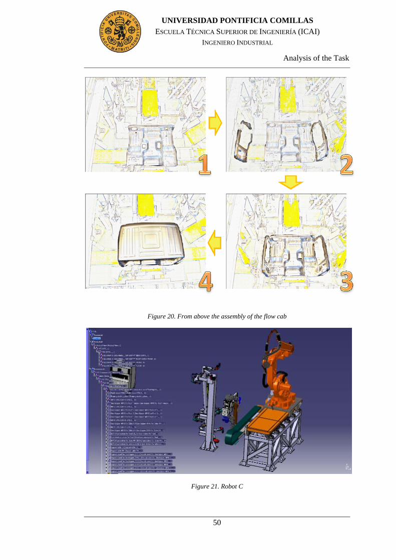
Analysis of the Task
50
UNIVERSIDAD PONTIFICIA COMILLAS
ESCUELA TÉCNICA SUPERIOR DE INGENIERÍA (ICAI) INGENIERO INDUSTRIAL
Figure 20. From above the assembly of the flow cab
Figure 21. Robot C

Analysis of the Task
51
UNIVERSIDAD PONTIFICIA COMILLAS
ESCUELA TÉCNICA SUPERIOR DE INGENIERÍA (ICAI) INGENIERO INDUSTRIAL
If the last cab was low and the new is high, the flow is pretty different because
Robot C needs to leave the weld gun in the weld gun stand and it moves to take
the gripper to clamp the front roof member after the sides are in the fixture and it
moves to the fixture to leave the front roof member with the gripper in it. Now it
is the time when it goes to the weld stand, it takes the weld gun and it begins to
spot welding the front roof member with all and to the sides with the roof. After
this, the next step is to unclamp the weld gun in its stand and it moves to the
fixture to take the empty gripper and later it goes to the home position to wait to a
new production. If the previous cab was high and the next was low, the Robot C
would go to clamp the weld gun and after the roof was in the fixture it begins to
weld, as it can be seen in the figure bellow, and later it would return to the home
position. The last case would be if there is a high cab two consecutive times where
Robot C would wait to the floor with the empty gripper and it would only have to
clamp the front roof member in the front roof stand and when the sides are in the
fixture it would leave the gripper and the part in the fixture and it will take the
weld gun from the weld gun stand and spot weld before coming back to home
position like in the second case (Low-High).

Analysis of the Task
52
UNIVERSIDAD PONTIFICIA COMILLAS
ESCUELA TÉCNICA SUPERIOR DE INGENIERÍA (ICAI) INGENIERO INDUSTRIAL
Figure 22. Robot C spot welding in a low cab
These sequences can be seen later in the flows diagrams that will be used to verify
the process and to give the logic in order to obtain the virtual simulation of the
work cell.
In the next figure, it can be seen the empty fixture. It is possible to see in the next
figures the fixture. It is also possible to see the clamps to hold the grippers for the
different parts with the sensors indicating it.

Analysis of the Task
53
UNIVERSIDAD PONTIFICIA COMILLAS
ESCUELA TÉCNICA SUPERIOR DE INGENIERÍA (ICAI) INGENIERO INDUSTRIAL
Figure 23. Fixture
Figure 24. Fixture with the cabin in it Figure 25.Empty fixture
The task of the fixture is to keep the different parts along the process while the
robots change their tools and finish the complete assembly of the cab. Later, the
transporting conveyor (brown conveyor in the picture bellow) comes and takes the
cab to bring it to the next station.

Analysis of the Task
54
UNIVERSIDAD PONTIFICIA COMILLAS
ESCUELA TÉCNICA SUPERIOR DE INGENIERÍA (ICAI) INGENIERO INDUSTRIAL
Figure 26. Station Y
3.2 MANUFACTURING HUB
The PPR family of products provides DELMIA V5 users the capability of directly
access, edit and manage data stored in the Manufacturing. These three products
are the DELMIA PPR Manufacturing Hub Navigator, DELMIA PPR Editor, and
DELMIA Manufacturing Lifecycle Management.
DELMIA PPR Manufacturing Hub Navigator provides efficient navigation of
product, process, and resource data, along with their related entities (fasteners)
and it also provides tools to search and to display properties of PPR objects, as
well as visualize (preview) the selected product or resource in a dedicated 3D
viewer. It provides cross-highlighting between the PPR tree and 3D viewer.(19)
DELMIA PPR Editor provides basic authoring capabilities in the Navigator
environment including attribute editing, deletion of process and resource
detailing, and the ability to create new processes.
DELMIA Manufacturing Lifecycle Management delivers the tools to manage the
lifecycle of process and resource data stored in the Manufacturing Hub including

Analysis of the Task
55
UNIVERSIDAD PONTIFICIA COMILLAS
ESCUELA TÉCNICA SUPERIOR DE INGENIERÍA (ICAI) INGENIERO INDUSTRIAL
alternatives, versions, and status management. (20) The figure below outlines
some of the possibilities within PPR hub.
Figure 27. Delmia PPR (20)
Now, the PPR tree that will be used during the entire project in DELMIA
interface is going to be described. It is located at the left of the screen and it is
separated in three types of perspectives: Process, Product and Resource. It is
possible to have several of each type.

Analysis of the Task
56
UNIVERSIDAD PONTIFICIA COMILLAS
ESCUELA TÉCNICA SUPERIOR DE INGENIERÍA (ICAI) INGENIERO INDUSTRIAL
figure 28. Mainly views
An analysis of how the information is structured is made. It begins with the
highest level that it is possible to reach and it gets progressively specified in detail
the correspondence between the levels.
Process List contains most of the information in the views of processes or Process
View. They consist of two distinct subdivisions. They are called Process Structure
(PS) and Production Plan (PP), which contain essentially the same information,
but it is structured in a different way. Both are interrelated so that the information
contained in one of them is also accessible from the other and a change in any of
them will be reflected in both. However, each of them is optimized to manage a
different type of information. Production Plan; This subdivision of the light is
focused on managing and storing internal information of the FAL, regardless of
priority of how processes are organized. Process Structure; although it is possible
to access to the internal information processes, their main function is to organize
at the levels all aspects of the manufacturing line.
Resource List stores all the information about system resources. These views, as
well as the processes are structured in stations, from which hang all the resources
that are required for some of the routes belonging to it. Depending on the needs of
the factory, the same resource can be associated with more than one station.

Analysis of the Task
57
UNIVERSIDAD PONTIFICIA COMILLAS
ESCUELA TÉCNICA SUPERIOR DE INGENIERÍA (ICAI) INGENIERO INDUSTRIAL
figure 29. Resource List
In relation to the resources of the processes, it is necessary to define the stations in
the two views separately. Later, DELMIA enables partnerships between each path
and concrete resource.
Product List contains information about components, ie, raw materials or semi-
finished products out of a secondary line. It differs from previous ones in which it
is not structured in stations, directly defined products being able to be grouped
into sets with similar features called Production View.

Analysis of the Task
58
UNIVERSIDAD PONTIFICIA COMILLAS
ESCUELA TÉCNICA SUPERIOR DE INGENIERÍA (ICAI) INGENIERO INDUSTRIAL
3.3 LEARNING THE MANUFACTURING HUB
The Manufacturing Hub provides a mechanism by which PPR (Process, Product and Resource) data can be re-used and shared between different manufacturing planning disciplines, allowing users to work concurrently on conceptual pre-planning, rough planning and detailed planning, while continually enhancing and evolving the PPR.
The Manufacturing Hub stores its data within a database, allowing its users to build relationships between the various products, processes and resources. This allows each user to know the impact of the changes that they (or others) are making.
Manufacturing Hub commands can be accessed via the Insert > Manufacturing Hub Object and Tools > Manufacturing Hub Commands menu.(1)
Figure 30. Manufacturing Hub Menu bar (1)
3.3.1 DPM (DIGITAL PROCESS MANUFACTURING)-PROCESS
ENGINEER COMPATIBILITY
For proper operation, the release version and service pack level of the DPM-based application used (Process and Resource Definition, Machining, Body-in-White, Assembly) must identically match the release version and service pack level of DELMIA Process Engineer used. This means, for example, that DPM Process and Resource Definition Release 10 Service Pack 2 is supported only when used with Process Engineer Release 10 Service Pack 2.(1)
3.3.2 HOW TO MAKE TEMPLATE IN DELMIA PROCESS ENGINEER
Open DPM and log on to PPR Hub is needed. To create the own template it is
important to note that you should be logged on as ADMINISTRATOR in the PPR

Analysis of the Task
59
UNIVERSIDAD PONTIFICIA COMILLAS
ESCUELA TÉCNICA SUPERIOR DE INGENIERÍA (ICAI) INGENIERO INDUSTRIAL
HUB. The common problem is that the Project and Template in DPM looks
similar. So it is necessary to start by creating a project. Then from the project the
template is created. Then project does not exist only the template does. If by
mistake it is put the graphics and the path to the CATPARTS or CATPRODUCTS
files they were not been able to import when DELMIA is opened.
Once it has been created a new project and it has been logged on as
ADMINISTRATOR, it will be possible to create a new template.
Open DPM process library default Volvo template right click new
template
Name the resource and in graphics tab point it to the .CADPART,
.CADPRODUCT or .CGR file, e.g. gripper.
The idea is to create an exact resource centric approach (PPR TREE) i.e. template,
which then can be used to import in DELMIA having the required resource
structure.
Once template is finished as desired; open DELMIA BiW Process Planner Light
User and open project from PPR Hub. This will load the project with the same
hierarchy as made in DPM. The template when open in DELMIA looks like this:

Analysis of the Task
60
UNIVERSIDAD PONTIFICIA COMILLAS
ESCUELA TÉCNICA SUPERIOR DE INGENIERÍA (ICAI) INGENIERO INDUSTRIAL
Figure 31. Template opened in Delmia V5
It is very important to check the path of the resource file i.e. CADPART,
.CADPRODUCT or .CGR in the graphics tab so that the graphics become visible
in DELMIA environment. Other important thing to consider here is that, when it
is seen in the graphics in DELMIA environment, all the resources were not
exactly in the correct order as they should be. That means it is necessary to re
align them according to the work station. Especially the Robot Units need a lot of
careful attention to put the resources at their proper places.
In the case studied on this project, the most important part of the workcell was
station Y within Station X. It can be seen this line in the figure below.

Analysis of the Task
61
UNIVERSIDAD PONTIFICIA COMILLAS
ESCUELA TÉCNICA SUPERIOR DE INGENIERÍA (ICAI) INGENIERO INDUSTRIAL
Figure 32. Vitual model of Station Y
3.3.3 SELECTING A PROJECT FROM THE MANUFACTURING HUB
After having created the required workcell template in DPM and have saved it as
a Project, it creates a project in the Manufacturing Hub database. To load the
project in DELMIA click, Open Manufacturing Hub Project in the
Manufacturing Hub Commands toolbar, or select Insert > Manufacturing Hub
Object > PPR from a Project the menu bar. DELMIA Process Engineer login
dialogue box will appear. Log in to Process Engineer. The first time the
Manufacturing Hub is accessed in a DELMIA session, the user is prompted to log
in to DELMIA Process Engineer. Enter the proper name and password in the
respective text fields:

Analysis of the Task
62
UNIVERSIDAD PONTIFICIA COMILLAS
ESCUELA TÉCNICA SUPERIOR DE INGENIERÍA (ICAI) INGENIERO INDUSTRIAL
Figure 33. Process Engineer Dialogue box(1)
Select a project to open. Once it has been logged in, the Open Project dialog box
appears, which lists all of the projects currently stored in the Manufacturing Hub
database(1)

Analysis of the Task
63
UNIVERSIDAD PONTIFICIA COMILLAS
ESCUELA TÉCNICA SUPERIOR DE INGENIERÍA (ICAI) INGENIERO INDUSTRIAL
Figure 34. Open Project Dialogue box(1)

Analysis of the Task
64
UNIVERSIDAD PONTIFICIA COMILLAS
ESCUELA TÉCNICA SUPERIOR DE INGENIERÍA (ICAI) INGENIERO INDUSTRIAL
3.4 HOW TO POPULATE PRODUCT LIST
The product can be imported using “Import Product, Resources from Hub” button
.
Then to link the product with the assembly operation inside the process use
Assignment assistant for AST and then save.
Then it is the time to open the resource in Delmia V5 for editing and to link the
AST as the output of the Assembly Line. This can be done by clicking on “Insert
AST” button; a dialog box will appear showing the available Manufacturing
Assembly. Select the appropriate MA and assign it to the Assembly which will
assemble the particular assembly part.
DELMIA creates an output MA out of that inputs which were provided to the
specific Robot Station. This output manufacturing assembly can be seen under
Applications Tab within the PPR hub tree.
The manufacturing assembly thus import may consist of separate products, all
being assembled together to an output manufacturing assembly. It is therefore
important to check that the input products must have all of their constituent’s parts
being imported from the PPR hub or not. The number of parts making up a
specific manufacturing assembly increases as it moves down to the Production
Level. The Robot Station in this Final term Project assembles the front cab for the
trucks so the parts coming as the input to the station are complete products already
like side doors, roofs and etc.
3.5 ASSIGN ROBOT UNITS TO ACTIVITIES
After assigning the output MA to the Assembly Line (Line X) the next task is to
assign the robot units within the assembly to their respective activities which they
will perform.

Analysis of the Task
65
UNIVERSIDAD PONTIFICIA COMILLAS
ESCUELA TÉCNICA SUPERIOR DE INGENIERÍA (ICAI) INGENIERO INDUSTRIAL
Go to Fastening Process Planner module. Click on the Assign Resource tab then
click on the activity and then click on the robot unit in which it is wanted to
perform that activity. The robot unit gets assigned to the activity. In the same way
assign all the activities to the prescribed robot units.
3.6 LOAD FASTENERS IN DELMIA FROM ENOVIA
Fasteners are created in ENOVIA and they are saved in text mentioning the
attributes and then this text file is pushed into PPR hub of the project they are
created by using bridge. Bridge is a simple script created by Dassault Systèmes.
Go to Fastener Process Planner module. Click on load fasteners tab, a dialogue
box will open. The available fasteners which were pushed in from ENOVIA can
be selected for the available assembly product and can be assigned. Once it is
done, you can visualize the fasteners on the product. It is explained in more detail
in the following section
3.7 ASSIGN FASTENERS TO RESOURCES
While in Fastener Process Planner. Click on Assignment Assistant for Resources,
its dialogue box will appear. On the left hand side the “To Resource” drops down
list pick “Station Y”. Click on the products to find fasteners and click “Find
Joining Fasteners” the system will then mark all the fasteners related to the
marked products. Note that the “from resource” drop down list should have
“None” selected.
The next is to assign the fasteners to each robot units. This will sort and assign the
robots their fasteners to work on. This can be done in the similar way; the only
difference is to select the required robot unit from the ‘To Resource’ drop down
list.

Analysis of the Task
66
UNIVERSIDAD PONTIFICIA COMILLAS
ESCUELA TÉCNICA SUPERIOR DE INGENIERÍA (ICAI) INGENIERO INDUSTRIAL
3.8 DEFINING I/O SIGNALS
I/O’s are defined in two ways. One within the Workcell Sequencing and other is
inside CLM Device Logic through Ports. Workcell Sequencing module is used to
create sequence and to synchronize more than one resource (robot). The I/O’s
within this module are used to send or receive signals for the start or finish of the
certain tasks. The explanation of how workcell sequence I/O’s are read in DA will
be done later.
The aim of the robotic IO state is to synchronize the tasks of different robots.
When the tasks are run from the LCM logic, the synchronization of the IOs is
disabled.
3.9 DELMIA AUTOMATION
3.9.1 SFC CODES
After having defined the I/O’s it is possible to define the internal logic and the
behavior of the resource either by SFC or FBD language structure in DA. The
explanatory text as how to use SFC to incorporate the I/O’s can be found in
appendix A
3.9.2 HMI
Once the robot task is defined by using one of the two programming languages it
is possible to deploy Human Machine Interface. The guide lines for using and
implementing HMI can be found in the appendix A

Analysis of the Task
67
UNIVERSIDAD PONTIFICIA COMILLAS
ESCUELA TÉCNICA SUPERIOR DE INGENIERÍA (ICAI) INGENIERO INDUSTRIAL
3.9.3 PLC
Once internal logic of the robot and HMI are linked it is possible to control the
workcell simulation by virtual PLC.
3.10 SEQUENCE OF OPERATIONS (SOP)
There are a lot of advantages when planning the sequences of operations with
sequence planner. One of them is to design the process plan according to the
operations view or resource view. The approach that it is mostly used to plan the
sequences of operations is Resource based which is straight forward and it does
not need to consider the product design and process planning. Its hierarchical
sequence and simple structure makes it easier to use for PLC. The pre and post
conditions added in the operations make the modeling flexible with the possibility
of optimization.(12)
Figure 35. Working with Supremica

Analysis of the Task
68
UNIVERSIDAD PONTIFICIA COMILLAS
ESCUELA TÉCNICA SUPERIOR DE INGENIERÍA (ICAI) INGENIERO INDUSTRIAL
Supremica software has been used to verify that the sequence does not have
collisions or mistakes and as it can be seen in the figure bellow, the result was that
the system was nonblocking.
Figure 36. Verification of SOP using Supremica

Methodology
69
UNIVERSIDAD PONTIFICIA COMILLAS
ESCUELA TÉCNICA SUPERIOR DE INGENIERÍA (ICAI) INGENIERO INDUSTRIAL
Chapter 4. METHODOLOGY
Figure 37. Methodology of the Final Term Project
The figure above highlights the milestones within this Final Term Project. The
course of action was to start by creating template in DPM and then to add
kinematics to the workcell. In the mean while look for the gaps in information
from models in CATIA to DELMIA. Outline them and try to overcome that by
either expressing the information in a different manner or to add what is missing.
Create the SOP and verify that they are non-blocking by using supremica. If
blocking, look for the problem and make them in such a way so as they become

Methodology
70
UNIVERSIDAD PONTIFICIA COMILLAS
ESCUELA TÉCNICA SUPERIOR DE INGENIERÍA (ICAI) INGENIERO INDUSTRIAL
non-blocking. Once you are satisfied with the SOP and it is non-blocking as well,
the next step is to take it to DA from where a working PLC code will be generated
according to the specification defined. Test this PLC code with a virtual PLC
connected through HMI control panel. Evaluation and validation of the simulated
model controlled through virtual PLC with the originally created workcell comes
will be done and conclusions will be incurred out of the findings.
The first milestone in this Final term Project was to create the virtual model of the
station under observation. The work started off at VTC at Gropegårdsgatan.
Station Y within Main Line X at Umeå production facility at Volvo Trucks was
decided. ABB is responsible for the execution and implementation of the plant
atomization.
VTC has the virtual model of the station Y in DELMIA provided by ABB. There
is no simulation defined on the virtual station. The ABB model was discussed
with VTC personnel and studied in detail. ABB is working to build the simulation
virtual model. The intended date of delivery of the virtual simulation model is not
known. It is still not sure whether the simulation model will be verified against a
virtual PLC after generating the PLC code or not.
After fully understanding the ABB model it was decided to build a template
similar to the one ABB has made. The necessary files needed to build the working
station were gathered and a template of the working station was made using those
files. There were few files which were missing when comparing the files received
with the files in the ABB template. The collaboration with Volvo contact person
helped in providing the missing files. To create a workcell with four robot units
was a task more ruffled than difficult. The reason being; the number of files
related in the project. To tackle this, files were arranged in a similar pattern as
they should appear in the template within DPM.

Results
71
UNIVERSIDAD PONTIFICIA COMILLAS
ESCUELA TÉCNICA SUPERIOR DE INGENIERÍA (ICAI) INGENIERO INDUSTRIAL
Chapter 5. RESULTS
5.1 CREATING THE WORK CELL
In this section the different results that have been obtained are explained. The step
by step guide as how to create a cell is explained above in the Template section.
The detailed steps as how to define kinematics add logics towards simulating the
robot task are attached in appendix A.
First of all, as it has been said before in the report, this work focuses on the
DELMIA solutions towards Digital Manufacturing. After analysis and
investigations a template at VTC was created with the data provided. The work
continues on the same lines as it is explained in the Analysis section and it comes
up with a complete work cell along with Assembly Product and Fasteners
assigned to it. The fasteners were assigned through ENOVIA on to the product
under the supervision of VTC professionals.
The Product Flow Diagram made in the Gantt chart view of DELMIA was very
different to the actual flow that ABB made for Volvo principally because of two
reasons. Firstly, the notations and language used in the PFD was not friendly and
secondly, the PFD was incomplete. A trip to Umeå to critically analyze the actual
flow of sequences the robot units have in the station Y was made. The visit
fulfilled its purpose and any doubts about how the production cell operates got
cleared. Later, the PFD was translated for Planning the Sequence of Operations in
Sequence Planner which is explained in the following section.

Results
72
UNIVERSIDAD PONTIFICIA COMILLAS
ESCUELA TÉCNICA SUPERIOR DE INGENIERÍA (ICAI) INGENIERO INDUSTRIAL
5.2 PLANNING THE SOP
The sequence of operations for the robot station was created in Sequence Planner.
The figure shows each robot unit within are the SOP. The SOP’s namely Robot A
till Robot D represents the four robot units inside the station Y of Station X. The
constituents of the robot unit have been explained earlier in the report. The
remaining two SOP’s are for the fixture and for the transferring conveyor. The
transferring conveyor is responsible for bringing the floor in to the station. It also
carries the assembled cab out of the station. The states IN & OUT signifies the
start and the finish of the cycle respectively. The robots wait until they get the IN
signal from the transferring conveyor. The robots then start their sequence.
The complete sequence of the robot units, fixture and transferring conveyor are
attached in the appendix A.
Figure 38. SOP for Station Y
5.3 KINEMATICS
Station Y was created with the parts that Volvo and ABB offered. These parts,
geogrippers, stands, the fixure, etc. have not mechanisms defined in it. CATIA V5
was used to make this kinematics as it will be explained later in “last simulation”.
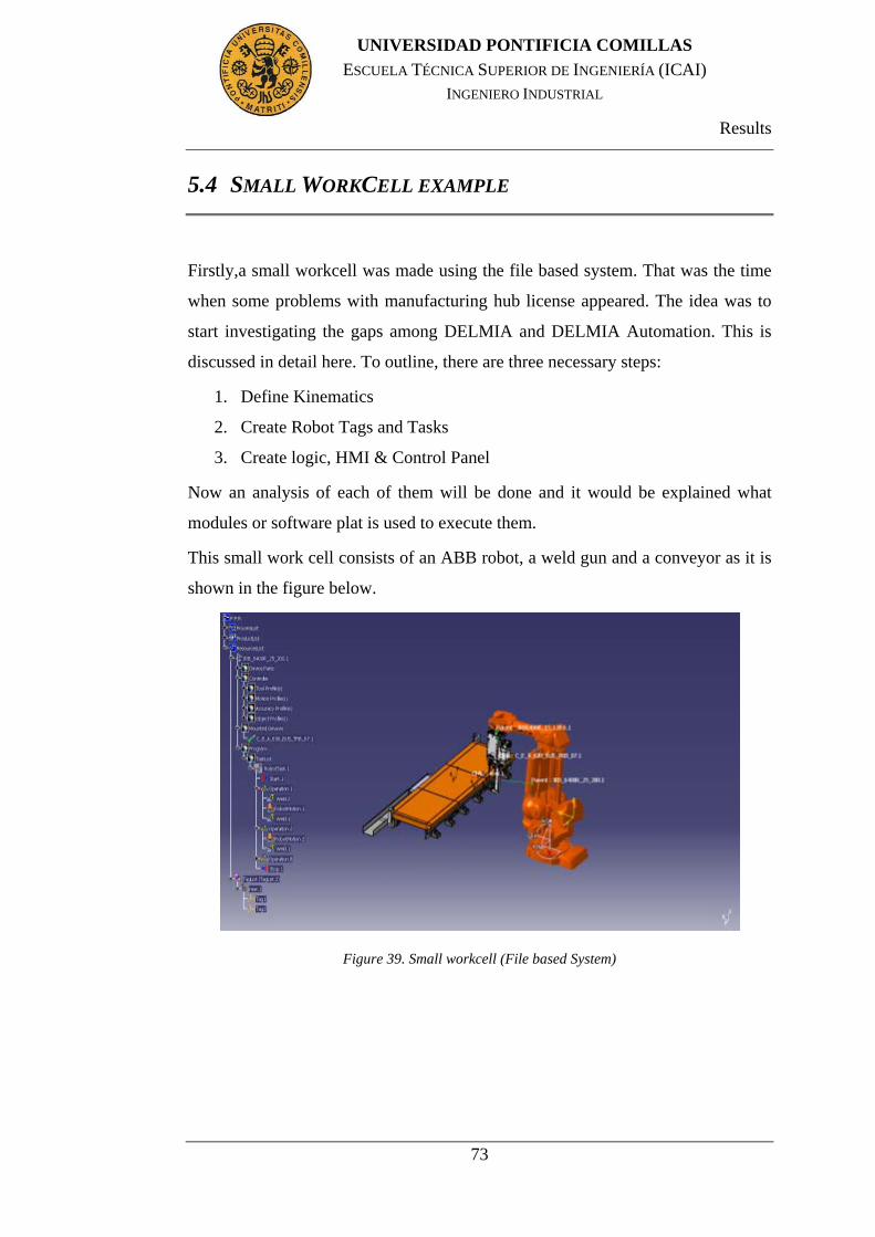
Results
73
UNIVERSIDAD PONTIFICIA COMILLAS
ESCUELA TÉCNICA SUPERIOR DE INGENIERÍA (ICAI) INGENIERO INDUSTRIAL
5.4 SMALL WORKCELL EXAMPLE
Firstly,a small workcell was made using the file based system. That was the time
when some problems with manufacturing hub license appeared. The idea was to
start investigating the gaps among DELMIA and DELMIA Automation. This is
discussed in detail here. To outline, there are three necessary steps:
1. Define Kinematics
2. Create Robot Tags and Tasks
3. Create logic, HMI & Control Panel
Now an analysis of each of them will be done and it would be explained what
modules or software plat is used to execute them.
This small work cell consists of an ABB robot, a weld gun and a conveyor as it is
shown in the figure below.
Figure 39. Small workcell (File based System)

Results
74
UNIVERSIDAD PONTIFICIA COMILLAS
ESCUELA TÉCNICA SUPERIOR DE INGENIERÍA (ICAI) INGENIERO INDUSTRIAL
5.4.1 DEFINE KINEMATICS
In this small workcell it is not necessary to define kinematics in CATIA. The
robot and the weld gun have kinematics that are already defined in them. A robot
from the ABB library available in DELMIA was used. The robots that will be
used in the real template will be of this type too.
5.4.2 CREATE ROBOT TAGS & TASKS
Once the kinematics are defined, the next step is to take the workcell with the
resources having the kinematics defined inside them to DELMIA in order to
create the required tags and then a robot task to perform those actions.
This is the same as described in Appendix A under “Task Definition section”.
5.4.3 CREATE LOGIC, HMI & CONTROL PANEL
When the robot task is the desired one, it is possible to open the workcell in DA
and define the logic here. DA works in a way that the user needs to define the
Internal Logic (IL) for the resources with kinematics. Here it is possible to link
the mechanism with the logic.
After IL’s are defined, it is necessary to define the ports as required. Usually start
task and finish task are enough. Give type as Boolean and direction as IN/OUT.
Then double click on behavior and structure the SFC logic code keeping the
sequences and other necessary things regarding robot task.

Results
75
UNIVERSIDAD PONTIFICIA COMILLAS
ESCUELA TÉCNICA SUPERIOR DE INGENIERÍA (ICAI) INGENIERO INDUSTRIAL
Figure 40. SFC code of the small workcell
Once everything is fine with the SFC LOGIC, define the same ports inside HMI
as well. Note that the ports should be exactly the same everywhere i.e. in robot, in
weld gun, in geo gripper, in HMI etc. There is no need to define the behavior of
HMI. To create the panel, move to HMI Control Panel design module and create
panel with the desired buttons. If there is a button and a light, it is important not to
forget to link the button with the light. Test the panel to check if it is working as
desired or not. Check the behavior tab as well and see if it is fixed or not fixed.
This explains the behavior of the button.
Go to “CSM Module and Block Editor” to create a new module within the robot
unit. This control module will act as a virtual PLC and it will be talking to the
robot unit through HMI. Inside the module it is necessary to create a block which
will be its internal logic. Create the same ports here too.
Now it is needed to link this virtual machine with the HMI so that the workcell
can be controlled through HMI. For this, an asynchronous external block which
will act as a bridge between HMI and Control Panel needs to be created. While
still in “Module and Block Editor” workbench click on Create asynchronous
block from external product tab, a dialogue box will be opened then click on the

Results
76
UNIVERSIDAD PONTIFICIA COMILLAS
ESCUELA TÉCNICA SUPERIOR DE INGENIERÍA (ICAI) INGENIERO INDUSTRIAL
control logic and then select the HMI control panel. Do not forget to check the
AUTOMATIC start in the end. This will launch the HMI automatically when the
control logic simulation runs.
Figure 41. HMI in the small workcell example
The last step is to create the execution environment under the station but outside
the robot unit. The robot station must have a robot unit (.catproduct) and
execution environments tab if they all collapse. Click on open connection editor
and click on “executionenv tab”. A new window will open with all the .catproduct
files with IL and ports. Connect the ports correctly and close the editor.
Run the simulation by clicking the execute button and then selecting the
“executionenv tab”.
5.5 FINAL SIMULATION
In the final simulation are discussed in detail, like in “the small workcell”, all the
steps from CATIA to the final PLC using the template. The template contains the
Robot unit A in Main Line X that it was described before.

Results
77
UNIVERSIDAD PONTIFICIA COMILLAS
ESCUELA TÉCNICA SUPERIOR DE INGENIERÍA (ICAI) INGENIERO INDUSTRIAL
To outline, there are four steps complete in this point, they are:
1. Defining the template
2. Defining Kinematics
3. Create Robot Tags and Tasks
4. Create logic, HMI & Control Panel
5.5.1 DEFINING THE TEMPLATE
Templates are created in DPE inside the project and they are saved in
Manufacturing Hub. When the project is opened in DELMIA environment, it can
be used the “Instantiate from template” button to populate the project with the
resources defined in the template.
To create the template and opening the project in DELMIA refer to “3.3.2 How to
Make Template in DELMIA Process Engineer” and “3.3.3 Selecting a Project
from the Manufacturing Hub”.
5.5.2 DEFINING KINEMATICS
Once the template has been made, CATIA has been used to define the kinematics.
To use the template, it was created in the work computer due to its difficulty when
export. In the project it has focused the CATIA work in the gripper of Robot A
and the fixture. Both have a lot of clamps that at the beginning were static,
without joints.

Results
78
UNIVERSIDAD PONTIFICIA COMILLAS
ESCUELA TÉCNICA SUPERIOR DE INGENIERÍA (ICAI) INGENIERO INDUSTRIAL
Figure 42. Geogripper where it has needed define kinematics
It has been explained how to define kinematics in the gripper and later it will be
done the same in the fixture. The first step is to open the CATproduct, from ABB,
that it contains all the parts. The problem that it has been found is that the parts
have a bad assemblance. The clamp it is only one CATpart so it is necessary to
separate the piece that it will move and the fixed piece in two different parts. To
separate this it is necessary to open one of the complete clamps in CATproduct in
a new window as it can be seen below.

Results
79
UNIVERSIDAD PONTIFICIA COMILLAS
ESCUELA TÉCNICA SUPERIOR DE INGENIERÍA (ICAI) INGENIERO INDUSTRIAL
Figure 43. Complete clamp opened in a new window
This CATproduct is separated in many parts. One of these parts is the clamp
where it is necessary to define the mechanism. This CATpart can be seen below.
Figure 44. The part of the clamp when it necessary to define the revolute joint

Results
80
UNIVERSIDAD PONTIFICIA COMILLAS
ESCUELA TÉCNICA SUPERIOR DE INGENIERÍA (ICAI) INGENIERO INDUSTRIAL
The pink piece is the part that will have a revolute joint around the green part. To
separate the pink piece and the fixed part it two new CATparts have been created.
Inside each CATpart, the pieces have been copied. In this work the two different
parts are like in the next figures.
Figure 45. Part with revolute joint inside the clamp
Figure 46. Fix part inside the clamp
Now, it is the time to replace the new two parts instead of the old part that has
been modified before in the full clamp. This is a CATproduct file where it will be

Results
81
UNIVERSIDAD PONTIFICIA COMILLAS
ESCUELA TÉCNICA SUPERIOR DE INGENIERÍA (ICAI) INGENIERO INDUSTRIAL
proceeded to define the joints. It has been necessary to be very careful with the
coordination due it is possible that have different global axis. To define the joint it
is necessary to create a new mechanism. Later, one part must be fixed, the green
part in this project. And finally the joints must be put. It has been put in the clamp
a revolute joint and later a lot of rigid joints so all the moving parts can move
around the green part altogether.
Figure 47. Making rigid joints with the pink part to move all together

Results
82
UNIVERSIDAD PONTIFICIA COMILLAS
ESCUELA TÉCNICA SUPERIOR DE INGENIERÍA (ICAI) INGENIERO INDUSTRIAL
Figure 48. Making the simulation to verificate the behaviur of one complete clamp
The last step when defining the kinematics is to define the travel limits and the
home positions. It has been considered that each clamp can be opened 120º. It has
been defined this position as “open home position” and 0º as “close home
position”.
Once this has been made with one clamp, the same steps must be done in the
others clamps in the gripper and the fixture.

Results
83
UNIVERSIDAD PONTIFICIA COMILLAS
ESCUELA TÉCNICA SUPERIOR DE INGENIERÍA (ICAI) INGENIERO INDUSTRIAL
Figure 49. Geogripper after define the kinematics in clamps
Figure 50. In fixture have been defined the kinematics in clamps
5.5.3 CREATE ROBOT TAGS & TASKS
Once the kinematics have been defined in the CAD parts and a template is built
and the steps that were explained earlier have been completed, like linking the
MA (Manufacturing Assembly) to the assembly line and loading fasteners on the

Results
84
UNIVERSIDAD PONTIFICIA COMILLAS
ESCUELA TÉCNICA SUPERIOR DE INGENIERÍA (ICAI) INGENIERO INDUSTRIAL
products. The next step is to create the robot tasks. The robot tasks are created in
accordance to the sequence that the robot unit will follow. This part strictly
created on the actual choice and need for that particular workcell or unit.
The “Teach Device” or tags can be used to create the robot tasks. Activities like
tool pick, tool drop, pick part and spot weld can also be used according to the
need.
Figure 51. Creating Tags & Tasks
Once the robot tasks are done, run the simulation by pressing “Robot Task
Simulation” button. If satisfied, proceed with DA towards PLC code and defining
logics by using ports.
5.5.4 CREATE LOGIC, HMI & CONTROL PANEL
In order to develop a manufacturing automation system, it is necessary to
understand the manufacturing operations and their relationship. It is also very
important the sequence of operations, which is the basis for control logic design.
The operations have preconditions that are defined when they are allowed to start
executing, which also defines the sequence relations among them. It has been

Results
85
UNIVERSIDAD PONTIFICIA COMILLAS
ESCUELA TÉCNICA SUPERIOR DE INGENIERÍA (ICAI) INGENIERO INDUSTRIAL
created, as it can be seen in the picture below, this sequence using “Sequence
Planner” program.
Figure 52. Sequence of Robot A by using Sequence Planner
When the sequence was finished, it was verified using “Supremica”. The result
was that the sequence of operation was nonblocking. This means that there were
not collisions or mistakes between the operations, so it was possible to continue
creating the logic.

Results
86
UNIVERSIDAD PONTIFICIA COMILLAS
ESCUELA TÉCNICA SUPERIOR DE INGENIERÍA (ICAI) INGENIERO INDUSTRIAL
Figure 53. Non blocking in Supremica software
After the SOP was created and verified, the GRAFCET of the Robot A unit was
created in a paper, as it is shown in the next figure.

Results
87
UNIVERSIDAD PONTIFICIA COMILLAS
ESCUELA TÉCNICA SUPERIOR DE INGENIERÍA (ICAI) INGENIERO INDUSTRIAL
Figure 54. GRAFCET of robot A unit
An internal logic in DELMIA Automation was created when the idea was clear.
The module “CLM Device Logic Design” that is inside “Logic Design” was used.
Later, the internal logic was defined in SFC code. Clicking two times in behavior
a new window to work in SFC opens. The ports and its characteristics were
defined as it is possible to see in the picture below.

Results
88
UNIVERSIDAD PONTIFICIA COMILLAS
ESCUELA TÉCNICA SUPERIOR DE INGENIERÍA (ICAI) INGENIERO INDUSTRIAL
Figure 55. Defining ports
Finally, the SFC was created based on the tasks and operations that have been
defined before.
Figure 56. SFC code of robot unit A
When the SFC code has finished, it is necessary to verify and optimize it using the
simulation tool before creating and linking the HMI.

Results
89
UNIVERSIDAD PONTIFICIA COMILLAS
ESCUELA TÉCNICA SUPERIOR DE INGENIERÍA (ICAI) INGENIERO INDUSTRIAL
Figure 57. Simulating the SFC code in DELMIA
Once planning and sequencing in DELMIA has been done, shift to product view
instead of process as DA works with product and not with process. The complete
explanation of working with DA is explained in Appendix A.

Results
90
UNIVERSIDAD PONTIFICIA COMILLAS
ESCUELA TÉCNICA SUPERIOR DE INGENIERÍA (ICAI) INGENIERO INDUSTRIAL
Figure 58. Connecting Ports
After the IL’s are defined completely, it is time to connect the ports with HMI and
the virtual PLC. This should be done with intense care and keeping the logic
defined in the SFC in mind. To create connections go to CSM Device Control
Connection module and click on “open connection editor” button, a new window
with the environment as shown in figure 56 will open. The devices with IL along
with their ports appear in this view. Also, HMI and Control Panel (virtual PLC)
are available along with the ports for the connection.
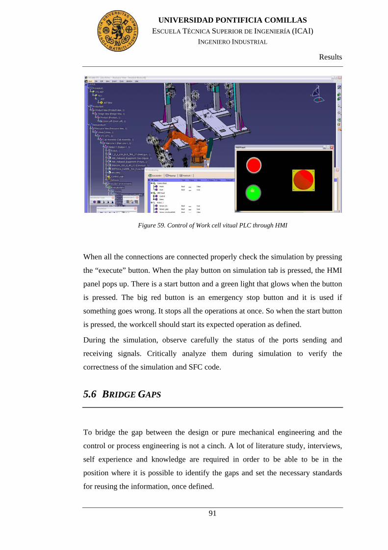
Results
91
UNIVERSIDAD PONTIFICIA COMILLAS
ESCUELA TÉCNICA SUPERIOR DE INGENIERÍA (ICAI) INGENIERO INDUSTRIAL
Figure 59. Control of Work cell vitual PLC through HMI
When all the connections are connected properly check the simulation by pressing
the “execute” button. When the play button on simulation tab is pressed, the HMI
panel pops up. There is a start button and a green light that glows when the button
is pressed. The big red button is an emergency stop button and it is used if
something goes wrong. It stops all the operations at once. So when the start button
is pressed, the workcell should start its expected operation as defined.
During the simulation, observe carefully the status of the ports sending and
receiving signals. Critically analyze them during simulation to verify the
correctness of the simulation and SFC code.
5.6 BRIDGE GAPS
To bridge the gap between the design or pure mechanical engineering and the
control or process engineering is not a cinch. A lot of literature study, interviews,
self experience and knowledge are required in order to be able to be in the
position where it is possible to identify the gaps and set the necessary standards
for reusing the information, once defined.

Results
92
UNIVERSIDAD PONTIFICIA COMILLAS
ESCUELA TÉCNICA SUPERIOR DE INGENIERÍA (ICAI) INGENIERO INDUSTRIAL
Due to CATIA & DELMIA are from the same company the information loss is
quite less. However, there is a need of stating the capabilities of them and the
discrepancies among them.
Roughly speaking, gaps are of two types, some are those that can be reused in
DELMIA from CATIA and others are those which cannot. So, if the design
person is defining the equipment in CATIA in one particular way which cannot be
used by the control engineer in DELMIA then there is no point of having the same
practice over and over again. The industry thus demands today, due to the tight
tolerances and lesser lead times, to have the preparatory work instructions
concise, clear and robust without having the risk of any short falls or rework.
If the .CATPARTS have been changed, it is necessary to make the
.CATPRODUCT again because it does not update automatically. All the parts
from Volvo are without kinematics. These parts have a bad subassembly too. The
little parts inside one part are badly defined so first of all it is necessary to
separate these parts in CATIA. This was like this due to the parts from Volvo
could not be simulated. Some parts are in .cgr due to the fact that by converting a
.CATpart file into a .cgr file the storage memory may decrease to a tenth the
original value with the consequence that more files will be able to fit in storage
and that process simulation will become smoother. It is preferred to wait with the
conversion into .cgr files until the model provides the results expected and no
more changes are going to be made.
The softwares that were used during the course of this work CATIA & DELMIA
sometimes crashed. The time lost due to such unexpected flaws was enormous.
For example if it was tried to define a rigid joint between a robot with a .CATpart
or .CATproduct file the program crashed. It is not possible to combine two
products having kinematics through a rigid joint.
To define a joint it is necessary to do it between two parts at the same level inside
the product in the PPR tree. Thus it can change the structure of the tree or in the
case of this project, in the template.

Results
93
UNIVERSIDAD PONTIFICIA COMILLAS
ESCUELA TÉCNICA SUPERIOR DE INGENIERÍA (ICAI) INGENIERO INDUSTRIAL
Process is separated from logic behavior. It is necessary to work according to the
tasks in DA rather than the process which defines the assembly operations. Thus
there can be a big gap between simulation of the virtual station and its simulation
based upon the logical expressions.
While using the clamping, picking activity it is not possible to execute all of the
clamps of gripper or fixture at once. This is different from the reality where all of
the different sensors senses the part at once and execute almost simultaneously.

Conclusions
94
UNIVERSIDAD PONTIFICIA COMILLAS
ESCUELA TÉCNICA SUPERIOR DE INGENIERÍA (ICAI) INGENIERO INDUSTRIAL
Chapter 6. CONCLUSIONS
This work therefore has been an effort to help Volvo Trucks to define in a better
way what they require from their design suppliers and what they can offer to their
process control engineers.
The conclusions have been achieved by answering the research questions. It has
been investigated and shown that it is possible to simulate a virtual workcell
following the Volvo PTS using DELMIA Solutions. It has been found that
working with PPR hub is very useful, as the information can be updated and
reused efficiently among CATIA and DELMIA. It is also shown in this Final
Term Project that it is possible to control a virtual workcell from HMI connected
with the virtual PLC.
The Final Term Project aims at the virtual preparation of Automation Station by
using DELMIA V5 platform. The main conclusion is that it is possible to do the
design, production planning and virtual commissioning of the Station, which are
the tree major steps with in digital manufacturing. Once everything has been
defined, it is possible to use and reuse what it has been done. DA (DELMIA
Automation) provides the necessary tools to create, edit, debug, and validate
control logic and it allows the user to create and reuse the predefined control logic
blocks.
Another conclusion is that the information, the geometry and the kinematics can
be read and they can be reused into DELMIA from CATIA. It has also been
explained that the kinematics must be made in CATIA although it is possible to
create them in DELMIA as well. Manufacturing hub is compatible to be used
while working with DA. This can be a great advantage for the automotive industry
as it would be easier and quicker to communicate, handle and update the data
through the manufacturing hub. This means that it is possible to transfer the data
from design engineer to the control or simulation engineer by using a single

Conclusions
95
UNIVERSIDAD PONTIFICIA COMILLAS
ESCUELA TÉCNICA SUPERIOR DE INGENIERÍA (ICAI) INGENIERO INDUSTRIAL
manufacturing hub interface. Then all of the logic defined can be sent back to the
customer like VTC for final verification and implementation. This can lead the
industry to use DA along with DELMIA with the manufacturing hub.

Future work
96
UNIVERSIDAD PONTIFICIA COMILLAS
ESCUELA TÉCNICA SUPERIOR DE INGENIERÍA (ICAI) INGENIERO INDUSTRIAL
Chapter 7. FUTURE WORK
It has been demonstrated that it is possible to do a virtual simulation of the
workcell. This research it has focused on the work in the Station Y inside Main
Line X. This work could be extended to the whole Main Line X.
It has also been shown that it is possible to control the virtual station by using
HMI and a virtual PLC. Future work could be done in order to implement this in
the real PLC so it could be used in the real Main Line X. Once the virtual PLC
program has been downloaded to the real PLC using the correct DELMIA
Automation PLC Setup, the controlled system simulator can be used to link the
real PLC and the virtual equipment using open connectivity. The user can define
the simulation environment, as previously described, and perform the production
system analysis and reporting. Operations can be created with the real HMI
connected to the real PLC. The DELMIA Automation Control System Simulator
can be used for virtual startup, virtual commissioning with the final user, and
operation training.
As it was mentioned before, cycle times have been taken into account slightly,
without been optimized during this research work as they were not provided by
VTC. So in the future it will be interesting to see the simulation and control of the
work cell with actual cycle times added to it.
This work that has been done with Volvo could be reused in other companies in
order to simulate other production stations. Working guides have been attached in
the appendix A of this Final Term Project in order to outline, as a tutorial, the
different steps that need to be followed to achieve virtual automation stations by
using DELMIA solutions.

Bibliography
97
UNIVERSIDAD PONTIFICIA COMILLAS
ESCUELA TÉCNICA SUPERIOR DE INGENIERÍA (ICAI) INGENIERO INDUSTRIAL
Chapter 8. BIBLIOGRAPHY
1. Systèmes, Dassault. DELMIA Version 5 Release 19 User's Documentation.
2008.
2. Trucks, Volvo. Volvo Trucks Home. Volvo Trucks Home. [Online]
http://www.volvotrucks.com/trucks/global/en-gb/Pages/home.aspx.
3. Systèmes, Dassault. About Dassault Systèmes - Dassault Systèmes. PLM
Solutions, 3D CAD & simulation software - Dassault Systèmes. [Online]
http://www.3ds.com/company/about-dassault-systemes/our-vision/.
4. ARC, Advisory Group. DELMIA V5 Automation Platform: Merging Digital
Manufacturing with Automation. 2006.
5. Samir Dalili, Marcus Persson. Development of an Event Bases Robotics
Simulation Implemented in Process Simulate. Göteborg, Sweden : CHALMERS
UNIVERSITY OF TECHNOLOGY, 2009.
6. P. Glimvert, E. Hartwig, A. Larsson, E. Lindskog, L. Lundh, and A.
Ohldin. Virtuell utveckling och idrifttagning av tillverkningscell med 3d-
simulering. s.l. : page 8, 5 2009.
7. Dassault Systèmes. DELMIA V5 AUTOMATION. Såo Paulo, Brazil : s.n.
8. Joakim Davidson & Tobias Sennö. Interactive Control of a Virtual Machine.
Lund, Sweden : Department of Industrial Electrical Engineering and Automation
Lund University, 2005.
9. Galicia, Juan Carlos Fernandez Padron - CIS. TECNOLOGIA E DESENO.
Galicia, Spain : s.n.
10. Knut Åkesson, Martin Fabian and Hugo Flordal. Supremica in a Nutshell
– Draft. 2007.
11. Supremica. Supremica. Supremica. [Online] http://www.supremica.org/.

Bibliography
98
UNIVERSIDAD PONTIFICIA COMILLAS
ESCUELA TÉCNICA SUPERIOR DE INGENIERÍA (ICAI) INGENIERO INDUSTRIAL
12. Mohammad Reza Shoaei, Gizem Akkan. Verification, Optimization and
Synthesis of sequences of operations. 2009.
13. www.mitecnologico.es. Controladores Lógicos Programables.
http://www.mitecnologico.com/Main/ControladoresLogicosProgramablesPlc.
[Online]
14. J.Eck, David. Asynchronous Events: Polling Loops and Interrupts.
http://www.faqs.org/docs/javap/c1/s2.html. [Online]
15. Manual, PLC. http://www.plcmanual.com/plc-history. [Online]
16. Fernandez, Jose Manuel. INTRODUCTION TO NORM IEC 1131-3.
http://www.internet.ve/asic/iec1131-3.html. [Online] 2008.
17. VINNOVA. Research and innovation for sustainable growth. Research and
innovation for sustainable growth. [Online] http://www.vinnova.se/en/FFI-
English/About-FFI/.
18. FFI. STRATEGIC VEHICLE RESEARCH AND INNOVATION.
19. Dassault Systemés. DELMIA Virtual Production for Production
Performance. [Online] http://www.3ds.com/products/delmia/portfolio/delmia-
v5/all-
products/domain/Digital_Manufacturing_Foundations/product/PRM/?cHash=2a7c
a0ca5c8613f6652bc2b63d37b39c.
20. Systèmes, Dassault. Virtual construction, validation and simulation. 2005.
21. Systèmes, Dassault. Delmia LCM Studio Presentation.

List of Abbreviations
99
UNIVERSIDAD PONTIFICIA COMILLAS
ESCUELA TÉCNICA SUPERIOR DE INGENIERÍA (ICAI) INGENIERO INDUSTRIAL
Chapter 9. LIST OF ABBREVIATIONS
DELMIA Digital Enterprise Lean Manufacturing Interactive
Application
CATIA Computer Aided Three-dimensional Interactive Application
PLC Programmable Logic Controllers
BiW Body in White
I/O Inputs and Outputs
CAD Computer Aided Design
FFI Fordonsstrategisk Forskning och Innovation
DA DELMIA Automation
PLM Product Lifecycle Management
SFC Sequential Function Chart
STEP Standard for Exchange of Product model data, neutral file format
in CAD-software
VRML Virtual Reality Modeling Language, neutral file format in CAD-
software
DOF Degrees Of Freedom
3D 3 Dimensions
CAM Computer Aided Manufacturing
CAE Computer Aided Engineering
KBE Knowledge-based Engineering
PDM Product Development Management
HMI Human-machine interface
CAA Computer Aided Architecture
VINNOVA Swedish government agency

List of Abbreviations
100
UNIVERSIDAD PONTIFICIA COMILLAS
ESCUELA TÉCNICA SUPERIOR DE INGENIERÍA (ICAI) INGENIERO INDUSTRIAL
SOP Sequence of Operations
FKG Fordonskomponentgruppen
DPM Digital Process Manufacturing
PPR Product, Process and Resources
MA Manufacturing Assembly
AST Assembly Specification tree
MSD Manufacturing System Design
FBD Function Block Diagram
IC Integrated Circuit
IEC International Electrotechnical Commission
IEEE Institution of Electrical and Electronic Engineers
IL Instruction List
LD Ladder Diagram
MSE Mechanical Simulation Engine
R&D Research and Development
SFC Sequential Flow Chart
SRS Software Requirement Specification
VTC Volvo Truck Corporation
PFD Product Flow Diagram
PLM Product Lifecycle Managment
ABS Absolute value
FB Function block

Appendices
101
UNIVERSIDAD PONTIFICIA COMILLAS
ESCUELA TÉCNICA SUPERIOR DE INGENIERÍA (ICAI) INGENIERO INDUSTRIAL
Chapter 10. APPENDICES
10.1 APPENDIX A
10.1.1 BUILD LAYOUT (ROBOT UNIT)
Open DPM Right Click New Create Process & Resource View
Similarly, create Area, Line and then create Station within the line.
Instantiate from template button.
Click on this button. It is a library from where we can pick items (parts) .CGR &
.CADPART files etc.
Create robot unit under station.
Put robot, weld gun, cabinet, rail, fasteners, with in this robot unit.
Create one extra level of safety fences under station level.
Use type “resource” .name fence (this will be surrounding equipment).

Appendices
102
UNIVERSIDAD PONTIFICIA COMILLAS
ESCUELA TÉCNICA SUPERIOR DE INGENIERÍA (ICAI) INGENIERO INDUSTRIAL
10.1.2 MOVES TO .CGR FILES
The steps followed to give moves to the differents parts of the cell with files in cgr
format are normally the next:
1. Start -> Resource Detailing -> Device building
2. Insert -> Existing component… (Press product for open document
files)
Ej. V5 -> 432067 ->23->02-> Part1 & Part2
3. For .cgr is not possible to use joints and the process is the next (for create
a movement):
4. Take 1 part and create “Frames of interest”
5. The same with others parts
6. Select 1 frame of interest and put the “frame tip” that you need.
7. The same with others parts
8. Add a “new mechanism”
9. If you want fix one part with “fixed part”
10. Use “joint from axis” and selected the axis that you want and select
the “Joint type” in the box that was open. (click check in “angle driven”
for use in the simulation later)
11. Finally, make the simulation -> press “Jog mechanism”
a. If you want it is possible to use “travel limits” for defined some limits
of move
b. Define the “home positions” for part the initials conditions.

Appendices
103
UNIVERSIDAD PONTIFICIA COMILLAS
ESCUELA TÉCNICA SUPERIOR DE INGENIERÍA (ICAI) INGENIERO INDUSTRIAL
10.1.3 TASK DEFINITION
When the workcell has all the kinematics normally made in CATIA it is possible
to start with logic. This guideline is a help to do simulation and the logic in
DELMIA.
Open “Device Task Definition” (Process) module:
Insert existing products
Insert the robots
In the example, the small work cell was done with one robot, one
weldgun and some part to make the spot welding process.
Open “Device Building” (Product) module:
Define the “frames of interest”
Create the tool tags
Open “Device Task Definition” module again:
Create the “Tag Group”
Define the tags linking with the tool tags defined before
Define “New Task”
Add more Tags with “Add Task” if you need more task in the
process
Click, first “Robot Task”
Click the axis for the Tag.
Was created “Operation 1”
You can check in “Robot Simulation”
Put the correct times
Check if there are some collision

Appendices
104
UNIVERSIDAD PONTIFICIA COMILLAS
ESCUELA TÉCNICA SUPERIOR DE INGENIERÍA (ICAI) INGENIERO INDUSTRIAL
When the user is satisfied with the tags and operations he/she can go to “Work
cell Sequence” for I/O sequencing and multi resource simulation.
Now it is necessary to define I/Os and it would be easily created as
follows. It is important to pay attention because some robots and
device have the I/Os created in them.
New I/Os
Modify I/Os
Wait I/Os State
If the user wants to see the robots simulation, he/she can click in
“multi resource simulation” button. and click “Play”
Figure 60. Process Simulation Menu bar(1)
The I/Os in the Logic will be made in CLM (Ports), in the “small workcell”
example, that will be explain later in other guide line.

Appendices
105
UNIVERSIDAD PONTIFICIA COMILLAS
ESCUELA TÉCNICA SUPERIOR DE INGENIERÍA (ICAI) INGENIERO INDUSTRIAL
10.1.4 INTERNAL LOGIC AND HMI
Now the process and the sequence have been created, it is necessary to start with
the logic such as follows:
Open “CLM Device Logic Design”
“Add Internal Logic”
In DELMIA it is possible to work in SFC+ and FBD.
Normally it is used SFC+.
Define now the ports
Double Click in ports
All of these things are created like a Resource.
In the example of this project there are two tasks,
“task_start” and “task_finish”.
Double Click in “behavior” in the PPR tree, inside the “Internal Logic”
Now the window has been opened to work in SFC+ blocks
“Add steps”
“Add Transitions” according to link the steps
Write the conditions in transitions propierty
Put the actions in the block
“Start Task Action”
“End Task Transition”
Add Actions
Right Click
Ports
You can simulate clicking “Simulate and Debug”
Finally, it is necessary to create the HMI. To do this open “HMI Control Panel
Design”

Appendices
106
UNIVERSIDAD PONTIFICIA COMILLAS
ESCUELA TÉCNICA SUPERIOR DE INGENIERÍA (ICAI) INGENIERO INDUSTRIAL
“Create Panel Set”
“Create Panel”
“Edit Panel”
The panel can be easily checked in “Test Panel”

Appendices
107
UNIVERSIDAD PONTIFICIA COMILLAS
ESCUELA TÉCNICA SUPERIOR DE INGENIERÍA (ICAI) INGENIERO INDUSTRIAL
10.1.5 DELMIA AUTOMATION LCM STUDIO
LCM Studio is composed of the following workbenches.
The goal is to give the user the capability of creating the Control program from
scratch, to create the HMI and to validate it.
Figure 61. Workbenches in LCM
In LCM Editor it is possible to create the blocks to structure the project and to be
able to re-use several times the same block (the main block is represented with a
star *).

Appendices
108
UNIVERSIDAD PONTIFICIA COMILLAS
ESCUELA TÉCNICA SUPERIOR DE INGENIERÍA (ICAI) INGENIERO INDUSTRIAL
Figure 62. Creating blocks
For each block, different signals have to be defined or declared. The mapping of
blocks I/Os enables the communication between the blocks which have an
interface. The internals signals are only used inside the block, their value is not a
sent to another block.
Figure 63. Interface Block Manager

Appendices
109
UNIVERSIDAD PONTIFICIA COMILLAS
ESCUELA TÉCNICA SUPERIOR DE INGENIERÍA (ICAI) INGENIERO INDUSTRIAL
LCM Editor provides all of the tools required to perform PLC programming for it
offers four bars with their respective buttons.
1. Normal steps: append step, add step after, add step before, add branch and
add final step.
2. Parallel steps: add parallel step after, add parallel step before, add parallel
branch and restore convergence.
3. Actions: add data flow action (i.e. modify a signal value), add macro
action: creates a sub-program directly inside the block, it can’t be re-used,
add call action: runs the called instance and freeze action.
4. Transitions
To compile the PLC program LCM compiler has been used. It detects the syntax
and semantic errors, instantaneous loops and causality errors. It has a perform to
code optimization, to produce an intermediate code (LCMO) and translate in C
language.
There are two ways to test the PLC program; by forcing the signals values or by
using the control panel after mapping the signals of the panel and the program.

Appendices
110
UNIVERSIDAD PONTIFICIA COMILLAS
ESCUELA TÉCNICA SUPERIOR DE INGENIERÍA (ICAI) INGENIERO INDUSTRIAL
Figure 64. Behavior of the program visible n SFC+ view
In HMI Control Panel Design it is possible to create a realistic Control Panel with
all real details using:
1. Pre-defined gadgets; IOs effecting (push button, emergency button,
selector/switch, slider), IOs effected (light, text display, value display,
gauge) or passive gadgets (image, label)
Figure 65. Pre-defined gadgets
2. Gadgets signals automatically generated.

Appendices
111
UNIVERSIDAD PONTIFICIA COMILLAS
ESCUELA TÉCNICA SUPERIOR DE INGENIERÍA (ICAI) INGENIERO INDUSTRIAL
3. Gadgets format and customization; general properties: name and position,
Behavior properties: icons, fixed/not fixed, Value/graduation management
and Background color, text properties.
Figure 66. 2 values: closed and opened
4. Panel formats have got similar tools as in PowerPoint, align, layout <->
distribute, resize tools, front/back <-> Order, group/ungroup, etc.
5. Ability to test the control panel by forcing the signals values and
visualizing the results in the graphical view
Figure 67. Signal Monitoring, testing its behavior
LCM has as well added values that make this program in a concise, explicit and
rigorous way to design a control logic:
1. LCM Studio: high level editor to design the control logic of automated
systems

Appendices
112
UNIVERSIDAD PONTIFICIA COMILLAS
ESCUELA TÉCNICA SUPERIOR DE INGENIERÍA (ICAI) INGENIERO INDUSTRIAL
2. LCM Is a High Level Formal Language, independent of the
implementation (opposite to IEC61131-3).
3. LCM is based on a generative graphical tool with automatic generation of
graphical layout.
4. Complete identity between the simulated and the target executed
program.(21)

Appendices
113
UNIVERSIDAD PONTIFICIA COMILLAS
ESCUELA TÉCNICA SUPERIOR DE INGENIERÍA (ICAI) INGENIERO INDUSTRIAL
10.2 APPENDIX B
Figure 68. Sequence for Robot C

Appendices
114
UNIVERSIDAD PONTIFICIA COMILLAS
ESCUELA TÉCNICA SUPERIOR DE INGENIERÍA (ICAI) INGENIERO INDUSTRIAL
Figure 69.Sequence for robots unit A,B and D
Figure 70. Sequence for fixture and conveyor