Bombas y Motores de Engranajes
15
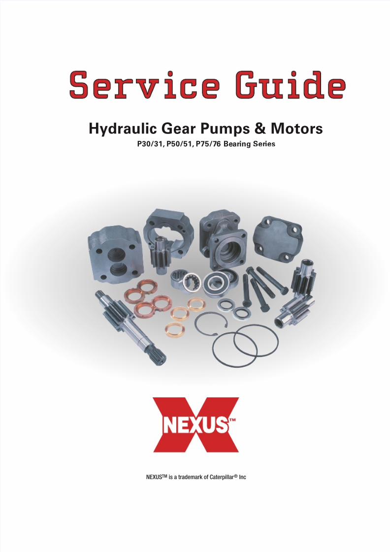
Hydraulic Gear Pumps & Motors P30/31, P50/51, P75/76 Bear ing Ser ies NEXUS TM is a trademark of Caterpillar ® Inc
Transcript of Bombas y Motores de Engranajes
8/6/2019 Bombas y Motores de Engranajes
http://slidepdf.com/reader/full/bombas-y-motores-de-engranajes 1/15
Hydraulic Gear Pumps & MotorsP30/31, P50/51, P75/76 Bearing Series
NEXUSTM is a trademark of Caterpillar ® Inc
8/6/2019 Bombas y Motores de Engranajes
http://slidepdf.com/reader/full/bombas-y-motores-de-engranajes 2/15
2
Pump and Motor Service InstructionsGeneral
This service manual will familiarize you with single and multiple section gear units and the components. Thelocation of each part and the proper method required for assembly and disassembly.
To facilitate repair, we suggest you first read the complete manual and familiarize yourself with the stepsrequired.
Dirt is a main factor in a poor repair job of any hydraulic system. The first requirement of good maintenanceon hydraulic equipment is a clean and tidy workstation.
Before assembly, is important to clean all parts and wipe them with a lint-less rag. Lint left on the bearing orbushing surfaces will cause damage to the unit and shorten life.
Use caution when gripping parts in a vise to avoid damage to machined surfaces. Check all replacement partsclosely to assure no damage has occurred during shipping and handling.
8/6/2019 Bombas y Motores de Engranajes
http://slidepdf.com/reader/full/bombas-y-motores-de-engranajes 3/15
3
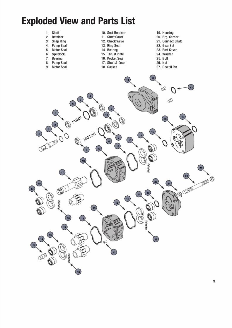
Exploded View and Parts List1. Shaft2. Retainer3. Snap Ring4. Pump Seal5. Motor Seal6. Spirolock 7. Bearing8. Pump Seal9. Motor Seal
10. Seal Retainer11. Shaft Cover12. Check Valve13. Ring Seal14. Bearing15. Thrust Plate16. Pocket Seal17. Shaft & Gear18. Gasket
19. Housing20. Brg. Carrier21. Connect Shaft22. Gear Set23. Port Cover24. Washer25. Bolt26. Nut27. Dowell Pin
4
1
2
3
6
7
5
10
9
11
13
7
6
14
15
17
18
1918
15
14
13
2013
16
21
14
15
22
18
19
18
15
1413
2324
25
26
16
8
12
16
27
P U M P
M O T O
R
8/6/2019 Bombas y Motores de Engranajes
http://slidepdf.com/reader/full/bombas-y-motores-de-engranajes 4/15
4
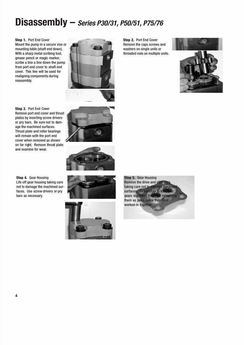
Disassembly – Series P30/31, P50/51, P75/76
Step 3 . Port End CoverRemove port end cover and thrustplates by inserting screw driversor pry bars. Be sure not to dam-age the machined surfaces.Thrust plate and roller bearingswill remain with the port endcover when removed as shownon far right. Remove thrust plateand examine for wear.
Step 4. Gear HousingLife off gear housing taking carenot to damage the machined sur-faces. Use screw drivers or prybars as necessary.
Step 5. Gear HousingRemove the drive and idler gerataking care not to damage machinedsurfaces. Be carefule to keep thegears together. You must reasemblethem as pairs, since they haveworked-in together.
Step 1. Port End CoverMount the pump in a secure vise ormounting table (shaft end down).With a sharp metal scribing tool,grease pencil or magic marker,scribe a line a line down the pumpfrom port end cover to shaft endcover. This line will be used forrealigning components duringreassembly.
Step 2. Port End CoverRemove the caps screws andwashers on single units orthreaded rods on multiple units.
8/6/2019 Bombas y Motores de Engranajes
http://slidepdf.com/reader/full/bombas-y-motores-de-engranajes 5/15
5
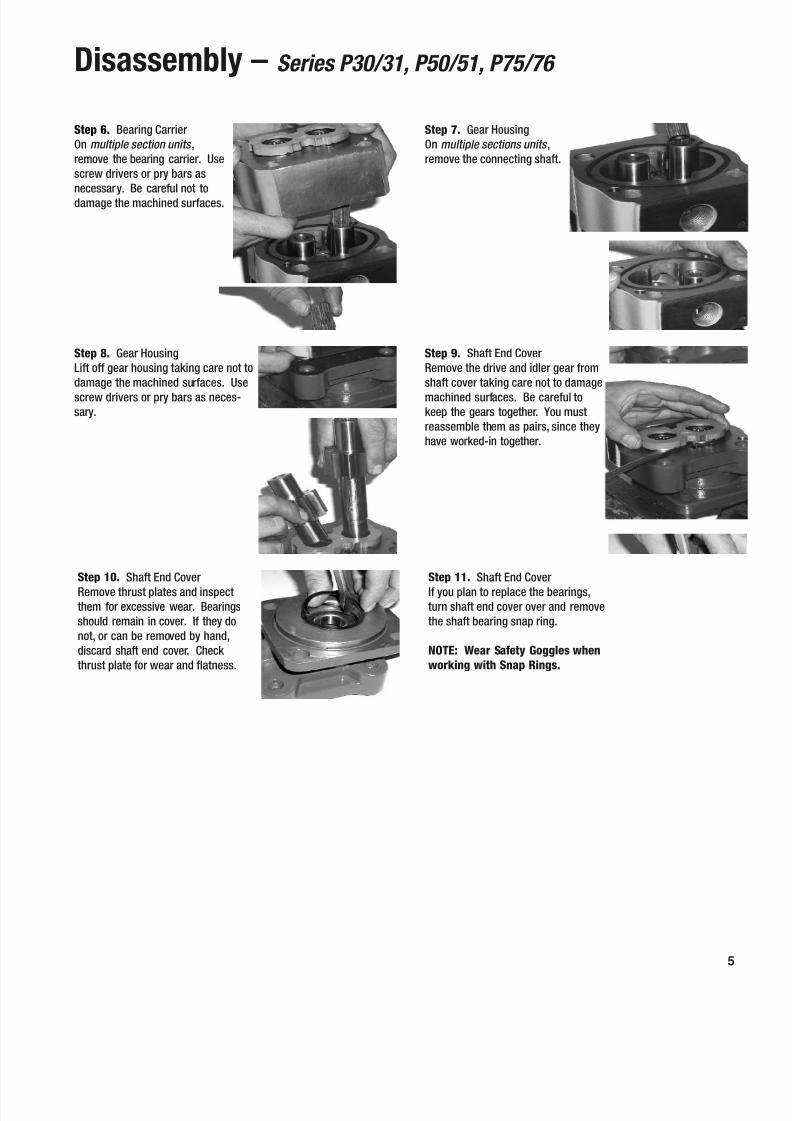
Disassembly – Series P30/31, P50/51, P75/76
Step 8. Gear HousingLift off gear housing taking care not todamage the machined surfaces. Usescrew drivers or pry bars as neces-sary.
Step 9. Shaft End CoverRemove the drive and idler gear fromshaft cover taking care not to damagemachined surfaces. Be careful tokeep the gears together. You mustreassemble them as pairs, since theyhave worked-in together.
Step 10. Shaft End CoverRemove thrust plates and inspectthem for excessive wear. Bearingsshould remain in cover. If they donot, or can be removed by hand,discard shaft end cover. Check thrust plate for wear and flatness.
Step 11. Shaft End CoverIf you plan to replace the bearings,turn shaft end cover over and removethe shaft bearing snap ring.
NOTE: Wear Safety Goggles whenworking with Snap Rings.
Step 6. Bearing CarrierOn multiple section units ,remove the bearing carrier. Usescrew drivers or pry bars asnecessary. Be careful not todamage the machined surfaces.
Step 7. Gear HousingOn multiple sections units ,remove the connecting shaft.
8/6/2019 Bombas y Motores de Engranajes
http://slidepdf.com/reader/full/bombas-y-motores-de-engranajes 6/15
6
Disassembly – Series P30/31, P50/51, P75/76
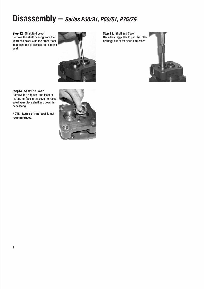
Step14. Shaft End CoverRemove the ring seal and inspectmating surface in the cover for deepscoring (replace shaft end cover isnecessary).
NOTE: Reuse of ring seal is notrecommended.
Step 12. Shaft End CoverRemove the shaft bearing from theshaft end cover with the proper tool.Take care not to damage the bearingseal.
Step 13. Shaft End CoverUse a bearing puller to pull the rollerbearings out of the shaft end cover.
8/6/2019 Bombas y Motores de Engranajes
http://slidepdf.com/reader/full/bombas-y-motores-de-engranajes 7/15
7
Assembly – Series P30/31, P50/51, P75/76
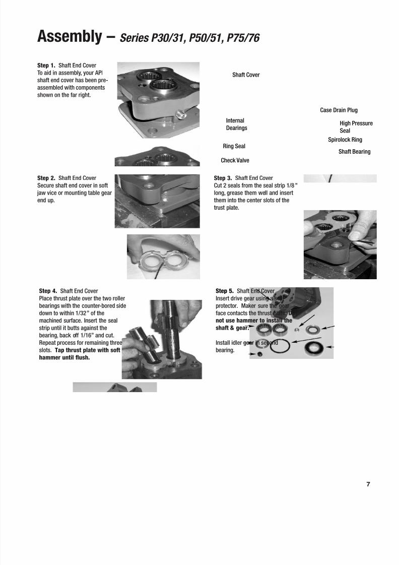
Step 2. Shaft End CoverSecure shaft end cover in soft
jaw vice or mounting table gearend up.
Step 3. Shaft End CoverCut 2 seals from the seal strip 1/8 ”long, grease them well and insertthem into the center slots of thetrust plate.
Step 4. Shaft End CoverPlace thrust plate over the two rollerbearings with the counter-bored sidedown to within 1/32 ” of themachined surface. Insert the sealstrip until it butts against thebearing, back off 1/16 ” and cut.Repeat process for remaining threeslots. Tap thrust plate with softhammer until flush.
Step 5. Shaft End CoverInsert drive gear using a sealprotector. Maker sure the gearface contacts the thrust plate. Donot use hammer to install theshaft & gear.
Install idler gear in secondbearing.
Step 1. Shaft End CoverTo aid in assembly, your APIshaft end cover has been pre-assembled with componentsshown on the far right.
Shaft Cover
InternalDearings
Ring Seal
Check Valve
Case Drain Plug
High PressureSeal
Spirolock Ring
Shaft Bearing
8/6/2019 Bombas y Motores de Engranajes
http://slidepdf.com/reader/full/bombas-y-motores-de-engranajes 8/15
8
Assembly – Series P30/31, P50/51, P75/76
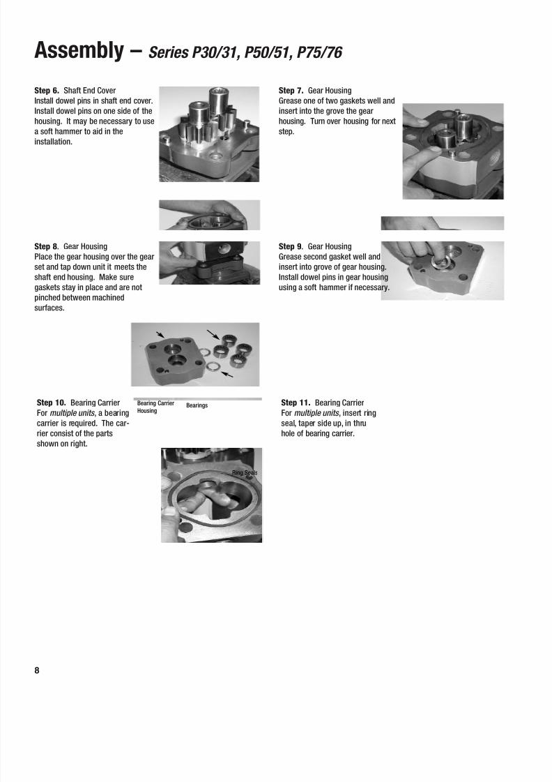
Step 8 . Gear HousingPlace the gear housing over the gearset and tap down unit it meets theshaft end housing. Make suregaskets stay in place and are notpinched between machinedsurfaces.
Step 9 . Gear HousingGrease second gasket well andinsert into grove of gear housing.Install dowel pins in gear housingusing a soft hammer if necessary.
Step 10. Bearing CarrierFor multiple units , a bearingcarrier is required. The car-rier consist of the partsshown on right.
Step 11. Bearing CarrierFor multiple units , insert ringseal, taper side up, in thruhole of bearing carrier.
Step 6. Shaft End CoverInstall dowel pins in shaft end cover.Install dowel pins on one side of thehousing. It may be necessary to usea soft hammer to aid in theinstallation.
Step 7. Gear HousingGrease one of two gaskets well andinsert into the grove the gearhousing. Turn over housing for nextstep.
Bearings
Ring Seals
Bearing Carrier
Housing
8/6/2019 Bombas y Motores de Engranajes
http://slidepdf.com/reader/full/bombas-y-motores-de-engranajes 9/15
9
Assembly – Series P30/31, P50/51, P75/76
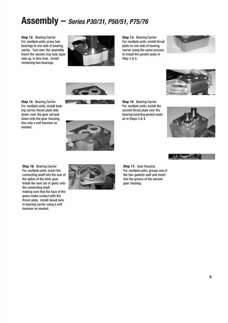
Step 14 . Bearing CarrierFor multiple units , install bear-ing carrier, thrust plate sidedown, over the gear set anddown onto the gear housing.Use only a soft hammer asneeded.
Step 15 . Bearing CarrierFor multiple units , install thesecond thrust plate over thebearing inserting pocket sealsas in Steps 3 & 4.
Step 16. Bearing CarrierFor multiple units , insert theconnecting shaft into the rear ofthe spline of the drive gear.Install the next set of gears ontothe connecting shaftmaking sure that the face of thegears make contact with thethrust plate. install dowel pinsin bearing carrier using a softhammer as needed.
Step 17. Gear HousingFor multiple units , grease one ofthe two gaskets well and insertinto the groove of the secondgear housing.
Step 12. Bearing CarrierFor multiple units , press twobearings in one side of bearingcarrier. Turn over the assembly.Insert the second ring seal, taperside up, in thru hole. Installremaining two bearings.
Step 13. Bearing CarrierFor multiple units , install thrustplate on one side of bearingcarrier using the same processto install the pocket seals inStep 3 & 4.
8/6/2019 Bombas y Motores de Engranajes
http://slidepdf.com/reader/full/bombas-y-motores-de-engranajes 10/15
10
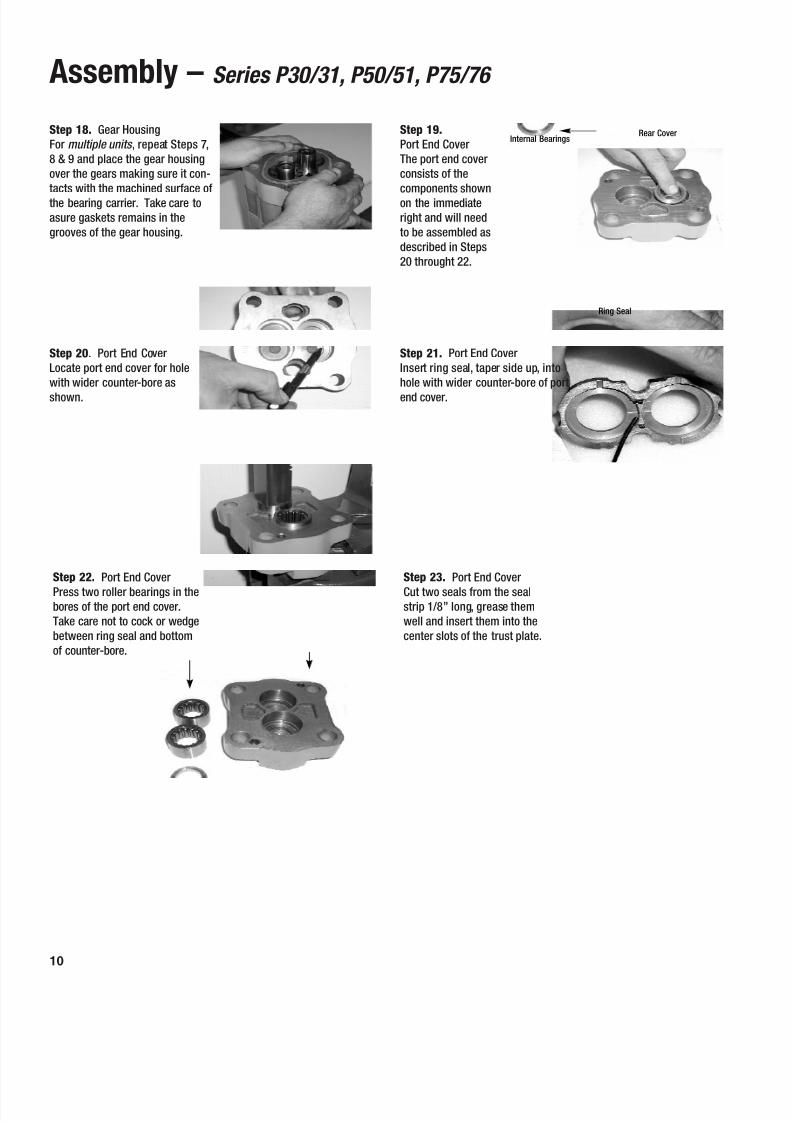
Assembly – Series P30/31, P50/51, P75/76
Step 20 . Port End CoverLocate port end cover for holewith wider counter-bore asshown.
Step 21. Port End CoverInsert ring seal, taper side up, intohole with wider counter-bore of portend cover.
Step 22. Port End CoverPress two roller bearings in thebores of the port end cover.Take care not to cock or wedgebetween ring seal and bottomof counter-bore.
Step 23. Port End CoverCut two seals from the sealstrip 1/8 ” long, grease themwell and insert them into thecenter slots of the trust plate.
Step 18. Gear HousingFor multiple units , repeat Steps 7,8 & 9 and place the gear housingover the gears making sure it con-tacts with the machined surface ofthe bearing carrier. Take care toasure gaskets remains in thegrooves of the gear housing.
Step 19.Port End CoverThe port end coverconsists of thecomponents shownon the immediateright and will needto be assembled asdescribed in Steps20 throught 22.
Internal Bearings
Ring Seal
Rear Cover
8/6/2019 Bombas y Motores de Engranajes
http://slidepdf.com/reader/full/bombas-y-motores-de-engranajes 11/15
11
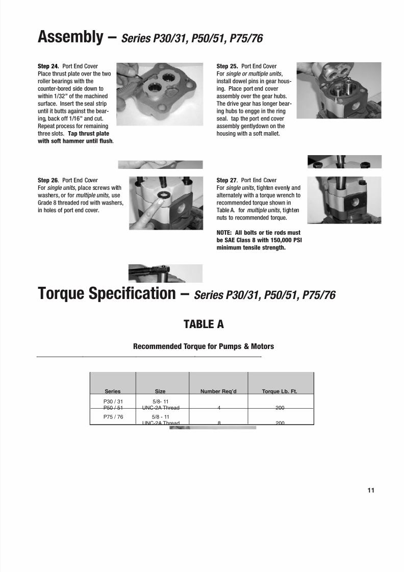
Assembly – Series P30/31, P50/51, P75/76
Step 26 . Port End CoverFor single units , place screws withwashers, or for multiple units, useGrade 8 threaded rod with washers,in holes of port end cover.
Step 27 . Port End CoverFor single units , tighten evenly andalternately with a torque wrench torecommended torque shown inTable A. for multiple units , tightennuts to recommended torque.
NOTE: All bolts or tie rods mustbe SAE Class 8 with 150,000 PSIminimum tensile strength.
Step 24. Port End CoverPlace thrust plate over the tworoller bearings with thecounter-bored side down towithin 1/32 ” of the machinedsurface. Insert the seal stripuntil it butts against the bear-ing, back off 1/16 ” and cut.Repeat process for remainingthree slots. Tap thrust platewith soft hammer until flush .
Step 25. Port End CoverFor single or multiple units ,install dowel pins in gear hous-ing. Place port end coverassembly over the gear hubs.The drive gear has longer bear-ing hubs to engge in the ringseal. tap the port end coverassembly gentlydown on thehousing with a soft mallet.
Torque Specification – Series P30/31, P50/51, P75/76
TABLE A
Recommended Torque for Pumps & Motors
P30 / 31 5/8- 11P50 / 51 UNC-2A Thread 4 200
P75 / 76 5/8 - 11UNC-2A Thread 8 200
Series Size Number Req’d Torque Lb. Ft.
8/6/2019 Bombas y Motores de Engranajes
http://slidepdf.com/reader/full/bombas-y-motores-de-engranajes 12/15
Start-Up & Test Procedure
1. Before starting a new or rebuilt pump, back off the system relief valve until the spring tension on the adjusting screw is relieved.This will avoid the possibility of immediate damage to the replacement unit in the event that the relief valve setting had beenincreased beyond the recommended operation pressure.
2. Before connecting any lines to the pump, fill all ports with clean hydraulic oil to provide initial lubrication. This is particularlyimportant when a pump is located above the reservoir.
3. The pump must be run in at low pressure (0-200 PSI) for 2 minutes before adjusting pressure settings. Raise the pressure tooperating pressure in increments of 300 PSI, pausing at each setting for 20-30 seconds.
4. Reset the main relief valve to its correct setting while the pump is operating at the maximum engine speed for the vehicle. Alwaysuse an accurate pressure gauge when adjusting the maximum engine speed for the vehicle. Always use an accurate pressuregauge when adjusting the pressure setting.
Recommended Test Procedure1. Be sure that you have enough oil supply (at least 1 gallon of oil for each G.P.M. of pump capacity).
• Keep this oil clean and free of dirt. Never use low viscosity, naphtha-based aircraft hydraulic fluids,or automotive brake fluids.
• Oils should be good quality – at least 150 SSU at 100 °F.
• Temperature should not exceed 120 °F for the test.
2. If testing a multiple unit, make sure there is enough oil for all sections and sections not being tested have unobstructed linesgoing to the oil reservoir.
3. The feed line must be of adequate size, no more than 5 ” Mercury Vac. as a rule. The feed line must provide a feed flow velocitynot in excess of 8 feet per second.
4. Hot oil must not be feed into a cold pump. This may cause the unit to seize.
5. Operate the pump for at least two minutes at ero pressure and not over 1,500 RPM.
6. Gradually increase the pressure to the desired test pressure.
7. The flow of oil should run close to the rated flows found in the performance chart of the catalog. NOTE: If used parts are installedin the unit, a 10% to 15% lower flow rate may be experienced and may be acceptable depending on the requirements of the unit.
12
8/6/2019 Bombas y Motores de Engranajes
http://slidepdf.com/reader/full/bombas-y-motores-de-engranajes 13/15
13
Start-Up & Test Procedure
Recommended Test Procedure (cont’d)
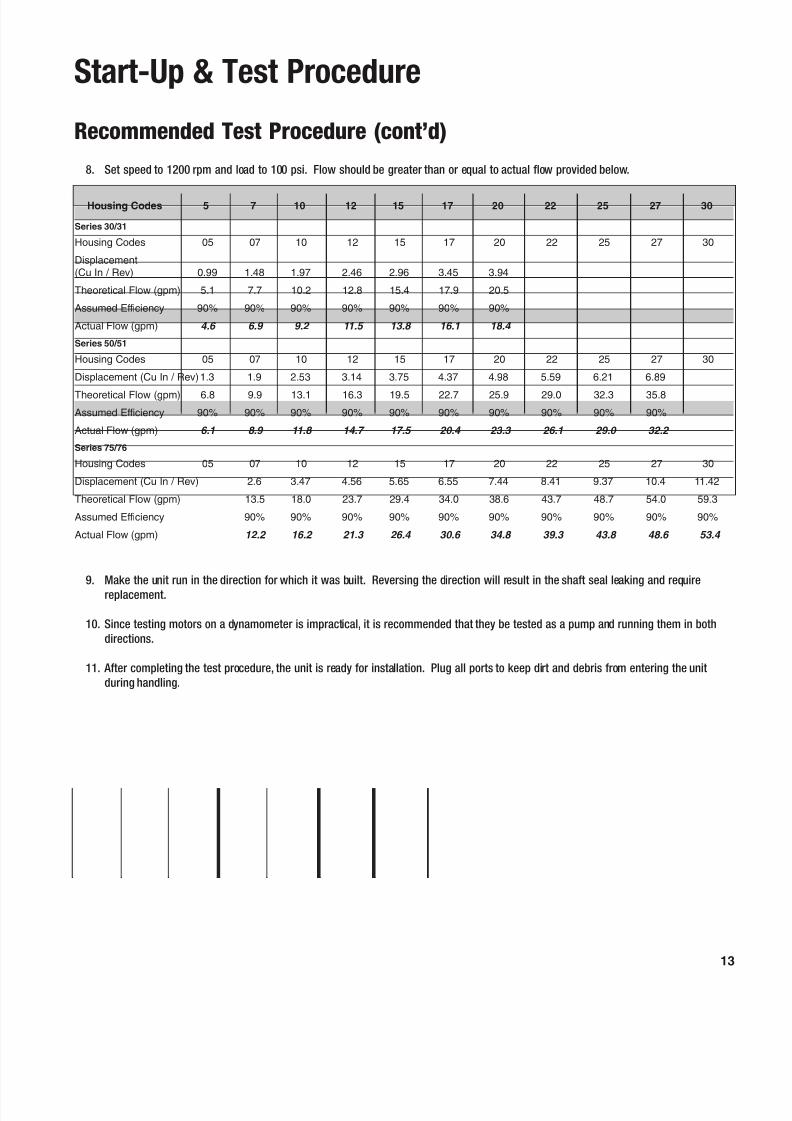
8. Set speed to 1200 rpm and load to 100 psi. Flow should be greater than or equal to actual flow provided below.
9. Make the unit run in the direction for which it was built. Reversing the direction will result in the shaft seal leaking and requirereplacement.
10. Since testing motors on a dynamometer is impractical, it is recommended that they be tested as a pump and running them in bothdirections.
11. After completing the test procedure, the unit is ready for installation. Plug all ports to keep dirt and debris from entering the unitduring handling.
Series 30/31
Housing Codes 05 07 10 12 15 17 20 22 25 27 30
Displacement(Cu In / Rev) 0.99 1.48 1.97 2.46 2.96 3.45 3.94
Theoretical Flow (gpm) 5.1 7.7 10.2 12.8 15.4 17.9 20.5
Assumed Efficiency 90% 90% 90% 90% 90% 90% 90%
Actual Flow (gpm) 4.6 6.9 9.2 11.5 13.8 16.1 18.4
Series 50/51
Housing Codes 05 07 10 12 15 17 20 22 25 27 30
Displacement (Cu In / Rev)1.3 1.9 2.53 3.14 3.75 4.37 4.98 5.59 6.21 6.89
Theoretical Flow (gpm) 6.8 9.9 13.1 16.3 19.5 22.7 25.9 29.0 32.3 35.8Assumed Efficiency 90% 90% 90% 90% 90% 90% 90% 90% 90% 90%
Actual Flow (gpm) 6.1 8.9 11.8 14.7 17.5 20.4 23.3 26.1 29.0 32.2
Series 75/76
Housing Codes 05 07 10 12 15 17 20 22 25 27 30
Displacement (Cu In / Rev) 2.6 3.47 4.56 5.65 6.55 7.44 8.41 9.37 10.4 11.42
Theoretical Flow (gpm) 13.5 18.0 23.7 29.4 34.0 38.6 43.7 48.7 54.0 59.3
Assumed Efficiency 90% 90% 90% 90% 90% 90% 90% 90% 90% 90%
Actual Flow (gpm) 12.2 16.2 21.3 26.4 30.6 34.8 39.3 43.8 48.6 53.4
Housing Codes 5 7 10 12 15 17 20 22 25 27 30
8/6/2019 Bombas y Motores de Engranajes
http://slidepdf.com/reader/full/bombas-y-motores-de-engranajes 14/15
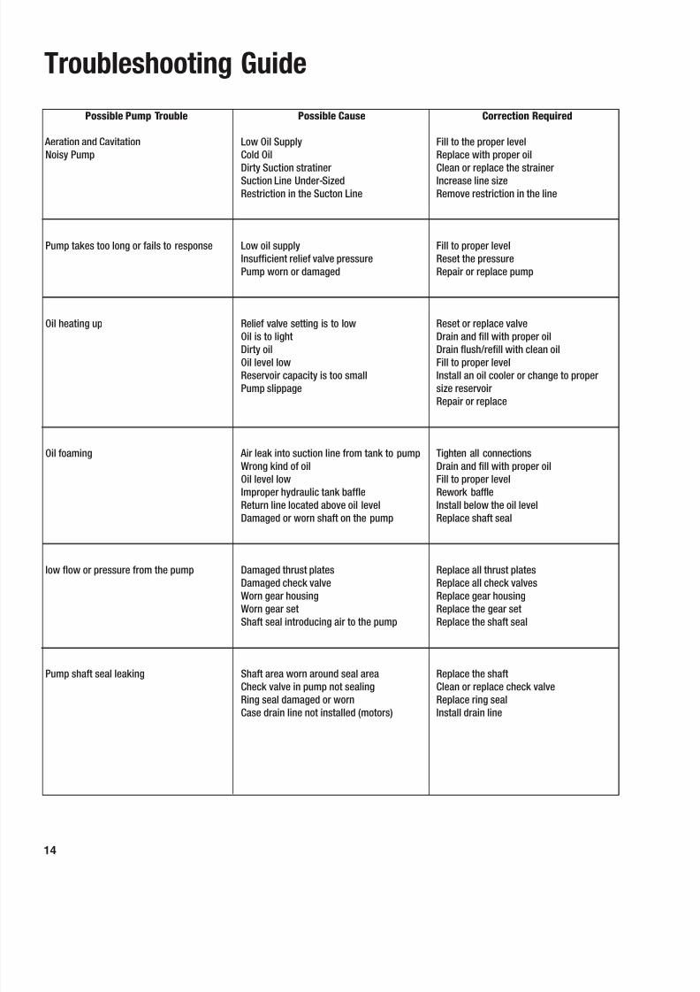
Troubleshooting Guide
Possible Pump Trouble
Aeration and CavitationNoisy Pump
Pump takes too long or fails to response
Oil heating up
Oil foaming
low flow or pressure from the pump
Pump shaft seal leaking
Possible Cause
Low Oil SupplyCold OilDirty Suction stratinerSuction Line Under-SizedRestriction in the Sucton Line
Low oil supplyInsufficient relief valve pressurePump worn or damaged
Relief valve setting is to lowOil is to lightDirty oilOil level lowReservoir capacity is too smallPump slippage
Air leak into suction line from tank to pumpWrong kind of oilOil level lowImproper hydraulic tank baffleReturn line located above oil level
Damaged or worn shaft on the pump
Damaged thrust platesDamaged check valveWorn gear housingWorn gear setShaft seal introducing air to the pump
Shaft area worn around seal areaCheck valve in pump not sealingRing seal damaged or wornCase drain line not installed (motors)
Correction Required
Fill to the proper levelReplace with proper oilClean or replace the strainerIncrease line sizeRemove restriction in the line
Fill to proper levelReset the pressureRepair or replace pump
Reset or replace valveDrain and fill with proper oilDrain flush/refill with clean oilFill to proper levelInstall an oil cooler or change to propersize reservoirRepair or replace
Tighten all connectionsDrain and fill with proper oilFill to proper levelRework baffleInstall below the oil level
Replace shaft seal
Replace all thrust platesReplace all check valvesReplace gear housingReplace the gear setReplace the shaft seal
Replace the shaftClean or replace check valveReplace ring sealInstall drain line
14

8/6/2019 Bombas y Motores de Engranajes
http://slidepdf.com/reader/full/bombas-y-motores-de-engranajes 15/15
© 2004 CaterpillarMedia Number: PECJ0001-01
NEXUSTM is a trademark of Caterpillar ® Inc