Catálogo de Breakers Compact NSX _ Masterpact _ Vigirex _ Power Logic _ SCHNEIDER ELECTRIC

Compact NS100 ➞ 630Compact NS630b-1600Masterpact NT, NW Merlin GerinAutomatisme UA / UA controller / Automatik UA /Automatismo UA / Automatismo UA
E59
083A
0 . OFF
0 . OFF
NR
R
N
N
R
auto
stop
manu
UN
ON
OFF
fault
UR
ON
OFF
fault
UN = O
UN = 1
compact NSMERLIN GERIN
UA automatism
200/240V 50/60 Hz
N
R
test
com
stop generatort5 (s)
t2 (s)
t4 (s)t3 (s)
t1 (s)
R
N
F Notice d'installation
EN Installation manual
DE Montageanleitung
IT Manuale di installazione
ES Instrucciones de instalación
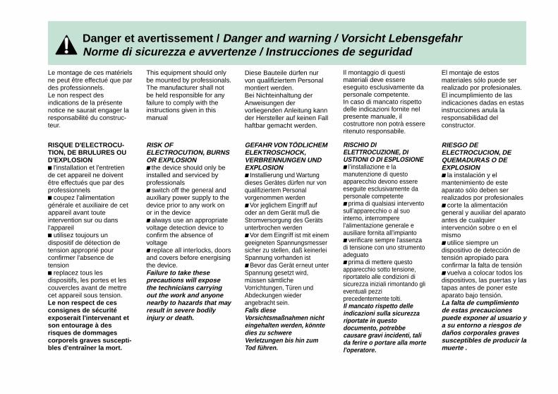
Danger et avertissement / Danger and warning / Vorsicht LebensgefahrNorme di sicurezza e avvertenze / Instrucciones de seguridad
Le montage de ces matérielsne peut être effectué que pardes professionnels.Le non respect desindications de la présentenotice ne saurait engager laresponsabilité du construc-teur.
This equipment should onlybe mounted by professionals.The manufacturer shall notbe held responsible for anyfailure to comply with theinstructions given in thismanual
Diese Bauteile dürfen nurvon qualifiziertem Personalmontiert werden.Bei Nichteinhaltung derAnweisungen dervorliegenden Anleitung kannder Hersteller auf keinen Fallhaftbar gemacht werden.
Il montaggio di questimateriali deve essereeseguito esclusivamente dapersonale competente.In caso di mancato rispettodelle indicazioni fornite nelpresente manuale, ilcostruttore non potrà essereritenuto responsabile.
El montaje de estosmateriales sólo puede serrealizado por profesionales.El incumplimiento de lasindicaciones dadas en estasinstrucciones anula laresponsabilidad delconstructor.
RISQUE D'ELECTROCU-TION, DE BRULURES OUD'EXPLOSIONc l'installation et l'entretiende cet appareil ne doiventêtre effectués que par desprofessionnelsc coupez l'alimentationgénérale et auxiliaire de cetappareil avant touteintervention sur ou dansl'appareilc utilisez toujours undispositif de détection detension approprié pourconfirmer l'absence detensionc replacez tous lesdispositifs, les portes et lescouvercles avant de mettrecet appareil sous tension.Le non respect de cesconsignes de sécuritéexposerait l'intervenant etson entourage à desrisques de dommagescorporels graves suscepti-bles d'entraîner la mort.
RISK OFELECTROCUTION, BURNSOR EXPLOSIONc the device should only beinstalled and serviced byprofessionalsc switch off the general andauxiliary power supply to thedevice prior to any work onor in the devicec always use an appropriatevoltage detection device toconfirm the absence ofvoltagec replace all interlocks, doorsand covers before energisingthe device.Failure to take theseprecautions will exposethe technicians carryingout the work and anyonenearby to hazards that mayresult in severe bodilyinjury or death.
GEFAHR VON TÖDLICHEMELEKTROSCHOCK,VERBRENNUNGEN UNDEXPLOSIONc Installierung und Wartungdieses Gerätes dürfen nur vonqualifiziertem Personalvorgenommen werdenc Vor jeglichem Eingriff aufoder an dem Gerät muß dieStromversorgung des Gerätsunterbrochen werdenc Vor dem Eingriff ist mit einemgeeigneten Spannungsmessersicher zu stellen, daß keinerleiSpannung vorhanden istc Bevor das Gerät erneut unterSpannung gesetzt wird,müssen sämtlicheVorrichtungen, Türen undAbdeckungen wiederangebracht sein.Falls dieseVorsichtsmaßnahmen nichteingehalten werden, könntedies zu schwereVerletzungen bis hin zumTod führen.
RISCHIO DIELETTROCUZIONE, DIUSTIONI O DI ESPLOSIONEc l’installazione e lamanutenzione di questoapparecchio devono essereeseguite esclusivamente dapersonale competentec prima di qualsiasi interventosull’apparecchio o al suointerno, interromperel’alimentazione generale eausiliare fornita all’impiantoc verificare sempre l'assenzadi tensione con uno strumentoadeguatoc prima di mettere questoapparecchio sotto tensione,riportatelo alle condizioni disicurezza iniziali rimontando glieventuali pezziprecedentemente tolti.Il mancato rispetto delleindicazioni sulla sicurezzariportate in questodocumento, potrebbecausare gravi incidenti, talida ferire o portare alla mortel'operatore.
RIESGO DEELECTROCUCION, DEQUEMADURAS O DEEXPLOSIONc la instalación y elmantenimiento de esteaparato sólo deben serrealizados por profesionalesc corte la alimentacióngeneral y auxiliar del aparatoantes de cualquierintervención sobre o en elmismoc utilice siempre undispositivo de detección detensión apropiado paraconfirmar la falta de tensiónc vuelva a colocar todos losdispositivos, las puertas y lastapas antes de poner esteaparato bajo tensión.La falta de cumplimientode estas precaucionespuede exponer al usuario ya su entorno a riesgos dedaños corporales gravessusceptibles de producir lamuerte .

Notice d'installation / Installation manual / Montageanleitung / Manuale d'installazione / Instrucciones de instalación
2
1
Ipush ON
O OFFdischarged
manuauto
2O OFF
1
2
1
Opush OFF
Ipush ON
I ONdischarged
manuauto
I ON dischargedO OFF
disc
push OFF
push ON
1
2
O
push OFF
push ON
Avant toute intervention sur l'appareil / Before working on the device / Vor jedem Eingriff am Gerät /Prima di qualiasi intervento sull'apparecchio / Antes de cualquier intervención sobre el aparato
4
Opush OFF
Ipush ON
O OFF
discharged
5
O OFF
discharged
push OFF
push ON
T TEST5
4
O OFF
push OFF
push ON
discharged
3
O OFFdischarged
E59
087A
E59
088A
E47
746A
E59
084A
E46
148A
appareil débrochable / drawout devices /Einschubtechnik / apparecchio estraibile /aparato seccionable
E47
082A
NS100 ➡ 630
NSNT
NW
NS630b-1600NTNW
1
Notice d'installation / Installation manual / Montageanleitung / Manuale d'installazione / Instrucciones de instalación
Outillage nécessaire / Necessary tools / ............................................ 3Benötigtes Werkzeug / Utensili necessari /Herramientas necesarias
Déballage / Unpacking / Auspacken / ............................................ 4-5Apertura dell'imballaggio / Desembalaje
Encombrements / Dimensions / Abmessungen / ............................... 6Ingombri / Dimensiones
Présentation ....................................................................................... 7Presentation ..................................................................................... 10Beschreibung ................................................................................... 13Presentazione .................................................................................. 16Presentación .................................................................................... 19
Schémas de câblage / Wiring diagrams / Schaltpläne / ............. 22-26Schemi elettrici / Esquemas de cableado
Installation / Installation / Installation / ....................................... 27-29Installazione / Instalación
Test / Tests / Test / Test / Test .................................................... 30-32
Synoptique de fonctionnement ........................................................ 33Operating diagrams ......................................................................... 35Flussdiagramm ................................................................................ 37Sinottico di funzionamento ............................................................... 39Esquema de funcionamiento ........................................................... 41
Sommaire / Contents / Inhalt / Sommario / Sumario
1
2
3
4
5
6
7
8
2

Notice d'installation / Installation manual / Montageanleitung / Manuale d'installazione / Instrucciones de instalación
E59
112A
Outillage nécessaire / Necessary tools / Benötigtes Werkzeuge / Utensili necessari / Herramientasnecesarias
1
Tournevis platTournevis cruciformeClé platePince multiprisePince coupantePince à dénuder.
Slotted screwdriverPhilips screwdriverSpannerAdjustable pliersWire cutterWire stripper.
SchraubendreherKreuzschraubendreherFlachschlüsselWasserpompenzangeSeitenschneiderAbisolierzange
Cacciavite piatto N. 2,5Cacciavite a croce N. 2Chiave inglese N. 8, 9Pinze.
Destornillador planoDestornillador estrellaLlave fijaTenazaAlicates de cortePelacables.
2,5 2
8-9
3

Notice d'installation / Installation manual / Montageanleitung / Manuale d'installazione / Instrucciones de instalación
R
N
N
R
auto
stop
manu
UN
ON
OFF
fault
UR
ON
OFF
fault
UN = O
UN = 1
compact NSMERLIN GERIN
N
R
test
com
stop generatort5 (s)
t2 (s)
t4 (s)t3 (s)
t1 (s)
0 . OFF
0 . OFF
NR
R
N
M5 x 12
COMM5
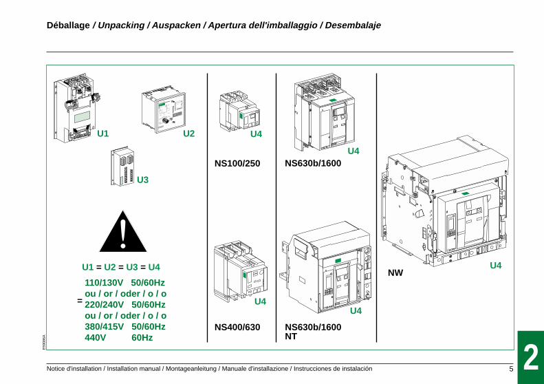
2Déballage / Unpacking / Auspacken / Apertura dell'imballaggio / Desembalaje
E59
085A
4
Notice d'installation / Installation manual / Montageanleitung / Manuale d'installazione / Instrucciones de instalación
0 . OFF
0 . OFF
NR
R
N
U3
U1 = U2 = U3 = U4
U2U1
NS100/250
NS400/630
NS630b/1600
NS630b/1600NT
NW
U4
U4
U4
U4
U4
R
N
N
R
auto
stop
manu
UN
ON
OFF
fault
UR
ON
OFF
fault
UN = O
UN = 1
compact NSMERLIN GERIN
N
R
test
com
stop generatort5 (s)
t2 (s)
t4 (s)t3 (s)
t1 (s)
UA automatism
200/240V 50/60 Hz
=
2
Déballage / Unpacking / Auspacken / Apertura dell'imballaggio / Desembalaje
E59
086A
110/130V 50/60Hzou / or / oder / o / o220/240V 50/60Hzou / or / oder / o / o380/415V 50/60Hz440V 60Hz
5

Notice d'installation / Installation manual / Montageanleitung / Manuale d'installazione / Instrucciones de instalación
110
110
4 Ø64 x M5
110
17,5 901059
145
145
140
140
95
90172187
82150
200
255
22
1386
140
140
138
200
4 Ø6
E59
095A
Encombrements / Dimensions / Abmessungen / Ingombri / Dimensiones 3
6
Notice d'installation / Installation manual / Montageanleitung / Manuale d'installazione / Instrucciones de instalación
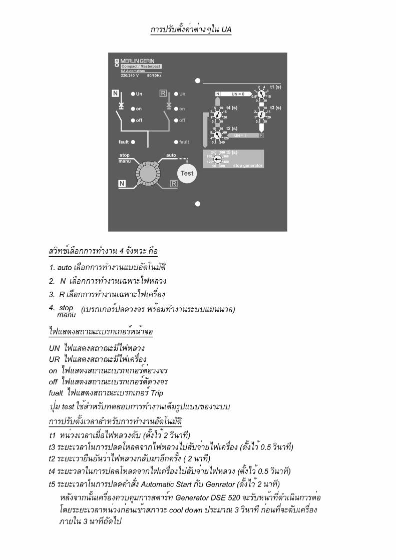
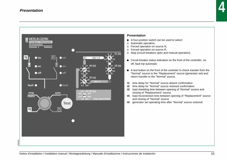
Presentation
Presentationc A four-position switch can be used to select:v Automatic operation,v Forced operation on source N,v Forced operation on source R,v Stop (circuit breakers open and manual operation).
c Circuit breaker status indication on the front of the controller: on,off, fault trip automatic
c A test button on the front of the controler to check transfer from the"Normal" source to the "Replacement" source (generator set) andreturn transfer to the "Normal" source.
t1: time delay for "Normal" source absent confirmationt2: time delay for "Normal" source restored confirmationt3: load shedding time between opening of "Normal" source and
closing of "Replacement" sourcet4: load reconnection time between opening of "Replacement" source
and closing of "Normal" sourcet4: generator set operating time after "Normal" source restored
E59
089A
4
stopmanu
auto
UA Automatism
UN
fault
off
on
RN UR
fault
off
on
220/240 V 50/60Hz
N UN = 0
1525 10
2010,5 30
t4 (s)
812 4
150,50,1 30
t1 (s)
1525 10
2010,5 30
t3 (s)
60815 30
12040,1 240
t2 (s)RUN = I
360180240 300
48012060 600
t5 (s)
stop generator
RN
Compact / Masterpact
Test
10

Notice d'installation / Installation manual / Montageanleitung / Manuale d'installazione / Instrucciones de instalación
Switch A: used to choose type of voltage monitoredSwitch B: used to select action in the event of a generator faultSwitch B = 1: No action.The priority load remains connected to the "Normal" source.Switch B = 0: The "Normal" source is opened.The load is isolated from the "Normal" source (no power supplied).Switch C : choice of value for T6 (120 to 180 s).
Additional control contacts(for control by external signals).
"Replacement" source voltage contactControlled by a specific test on the "Replacement" source.Transfert to "Replacement" source only if contact is closed.For example, this contact can be used to test the frequency of the"Replacement" source voltage.Transfer to the "Replacement" source will only take place if the testresult is within tolerances.This condition is not taken into account for return transfer to the"Normal" source.Voluntary transfer: (e.g. for energy management functions)An external signal can be used to initiate transfer to the"Replacement" source.The load returns to the "Normal" source when the signal is cleared.
4
10
812
6
14 1216
3
9
7
1
5
131115
BBus
BA
C
B=0B=1
N=offN=on
C=0C=1
t6=120st6=180s
EJP / voluntary transfer
fault generator
t maxstart generator
/ voltage
n°1
n°2
+ 0v 24v
+0v24v
24 N O L
N
0 1
E 25
si contact ferméif contact closed
ordre depermutationvolontaire (ex: EJP)voluntary transfer
17 18 20 21
RN
R
A=0
A=1 contrôle 33 control
contrôle /N ou / to N or to control
BA
C
B=0B=1
N=offN=on
C=0C=1
t6=120st6=180s
EJP / voluntary transfer
fault generator
t maxstart generator
A=0 contrôle /N ou / to N or to control
/ voltage
24 N O L
N
0 1
R E 25
si contact ferméif contact closed
ordre depermutationvolontaire (ex: EJP)voluntary transfer
17 18 20 21
RNA=1 contrôle 3
3 control
Presentation
E59
091A
4
UA contoller option
Adress setting using the two encoder wheels.Communication function can be used to check the following from aremote location:c Status of the circuit breakers (open, closed or fault trip).c Voltage presence on the "Normal" and "Replacement" sources.c Presence of an order forcing operation on the "Replacement"source (e.g. for energy management purposes).c Values of settings and configurations.c Status of the non-priority circuits (whether subject to loadshedding or not).
11

Notice d'installation / Installation manual / Montageanleitung / Manuale d'installazione / Instrucciones de instalación
0 . OFF
0 . OFF
NR
R
N
E59
092A
4
mad
e in
Fra
nce
161314 15 11 12 10 9 5 7 6 8
délestageload sheddingorder
démarrage groupegeneratorstart-up order
selecteurselector
30 29 3127 26 2823 22auto stop
NR
Output
c Generator set control signalc Shedding of non-priority circuitsc Indication of operation in automatic mode.
Presentation
E59
090A
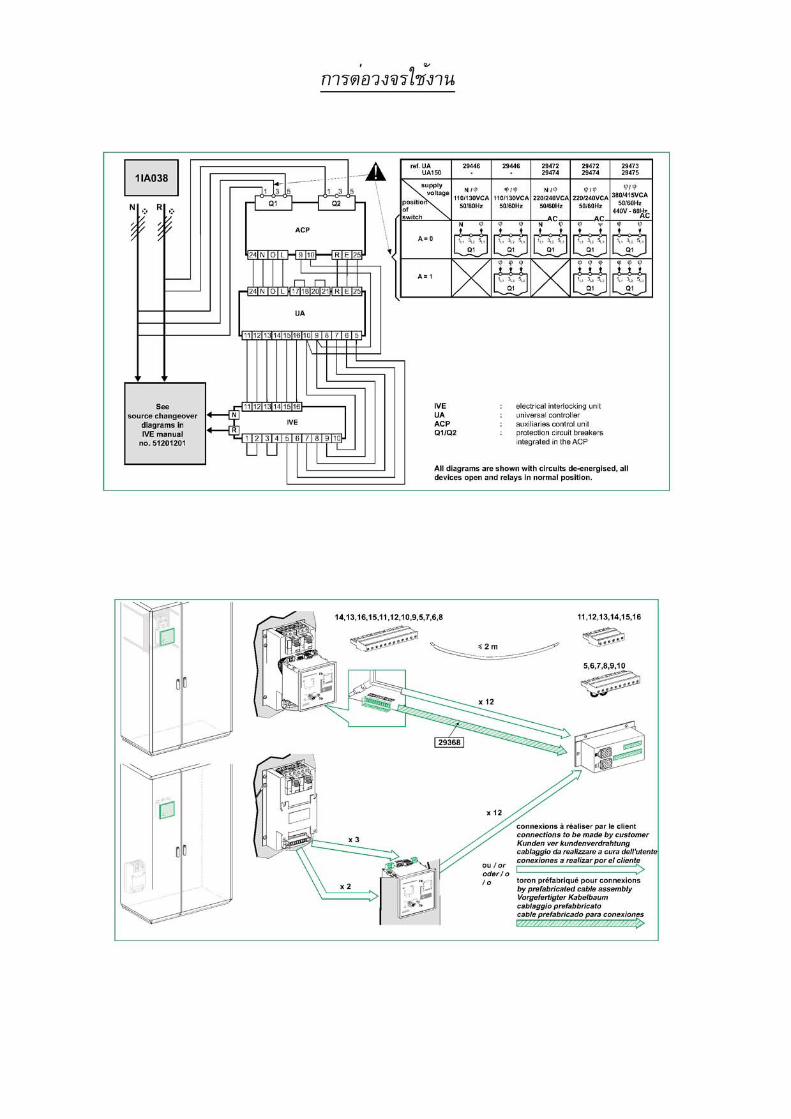
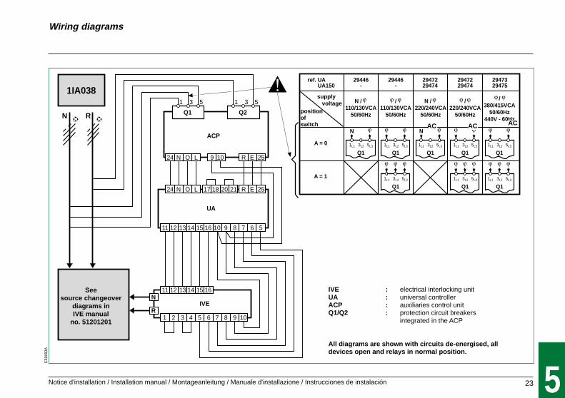
ACP auxiliaries control unit
The auxiliaries control unit is the power interface between the sources and the UA controller.It includes:c Two P25M circuit breakers supplying and protecting the automatic control circuits for the
"Normal" and "Replacement" sources.v The P25M circuit breaker of the "Normal" source can be opened to test controller
operation by simulating the absence of voltage UN.c Two relay contactors for the controller.c The terminal block for connection to the controller.
12
Notice d'installation / Installation manual / Montageanleitung / Manuale d'installazione / Instrucciones de instalación
ACP
IVE
UA
N R Q1
1 3 5
Q2
1 3 5
N
R
24 N O L
24 N O L
9 10 R E 25
R E 25
11 12 13 14 15 16 10 9 8 7 6 5
1 2 3 4 5 6 7 8 9 10
11 12 13 14 15 16
17 18 20 21
2947229474
2947229474
A = 0
A = 1
/220/240VCA
50/60Hz
/380/415VCA
50/60Hz440V - 60Hz
N
2947329475
ref. UAref. UA150
N / N220/240VCA
50/60Hz
1L1
Q1 Q1 Q1
Q1 Q1
3L2 5L3 1L1 3L2 5L3 1L1 3L2 5L3
1L1 3L2 5L3 1L1 3L2 5L3
1IA03829446
-
/110/130VCA
50/60Hz
Q1
Q1
1L1 3L2 5L3
1L1 3L2 5L3
29446-
N / N110/130VCA
50/60Hz
Q11L1 3L2 5L3
N
Wiring diagrams
E59
093A
5
IVE : electrical interlocking unitUA : universal controllerACP : auxiliaries control unitQ1/Q2 : protection circuit breakers
integrated in the ACP
All diagrams are shown with circuits de-energised, alldevices open and relays in normal position.
23
supply voltage
Seesource changeover
diagrams inIVE manual
no. 51201201
positionofswitch AC AC AC
Notice d'installation / Installation manual / Montageanleitung / Manuale d'installazione / Instrucciones de instalación
14,13,16,15,11,12,10,9,5,7,6,8
R
N
11,12,13,14,15,16
5,6,7,8,9,10
R
N
x 12
x 12
x 3
x 2
29368
R
N
y 2 m
6E59
103A
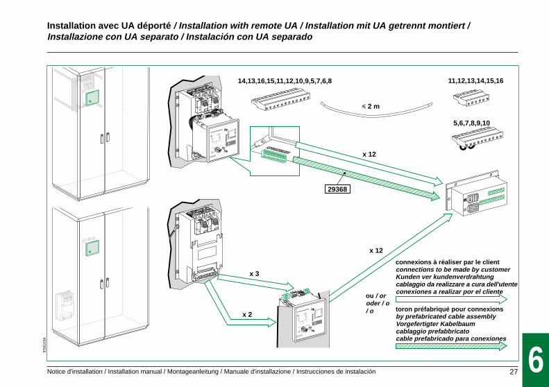
Installation avec UA déporté / Installation with remote UA / Installation mit UA getrennt montiert /Installazione con UA separato / Instalación con UA separado
connexions à réaliser par le clientconnections to be made by customerKunden ver kundenverdrahtungcablaggio da realizzare a cura dell'utenteconexiones a realizar por el cliente
ou / oroder / o/ o
27
toron préfabriqué pour connexionsby prefabricated cable assemblyVorgefertigter Kabelbaumcablaggio prefabbricatocable prefabricado para conexiones

Notice d'installation / Installation manual / Montageanleitung / Manuale d'installazione / Instrucciones de instalación
Installation avec UA déporté / Installation with remote UA / Installation mit UA getrennt montiert /Installazione con UA separato / Instalación con UA separado
E59
102A
6
R
N
4
5
x 9 / 2 m maxi
R
N
9
6
1
3
NR
RN
2
0,2 Nmx 4
8
x 4 7
28
Quand les bornes 17, 18, 20 et 21 ne sontpas utilisées, la présence d’un strap entre17, 18 et entre 20, 21 est impérative.Jumpers must be fitted between 17 and 18and between 20 and 21 when 17, 18, 20, 21are not used.Zwei Drahtbrücken sind obligatorischzwischen 17, 18 und 20, 21 wenn dieKlemmen nicht benutzt werden.Quando i morsetti 17, 18, 20 e 21 non sonoutilizzati è obbligatorio ponticellare imorsetti 17, 18 e i morsetti 20, 21Cuando las bornas 17, 18, 20 y 21 no seutilizan, es imprescindible la existencia deun puente entre 17 y 18 y entre 20 y 21
Notice d'installation / Installation manual / Montageanleitung / Manuale d'installazione / Instrucciones de instalación
E59
101A
6
0 . OFF
0 . OFF
NR
R
N
R
N
N
R
auto
stop
manu
UN
ON
OFF
fault
UR
ON
OFF
fault
UN = O
UN = 1
MERLIN GERIN
N
R
test
com
stop generatort5 (s)
t2 (s)
t4 (s)t3 (s)
t1 (s)
R
N
R
N
N
R
auto
stop
manu
UN
ON
OFF
fault
UR
ON
OFF
fault
UN = O
UN = 1
compact NSMERLIN GERIN
N
R
test
com
stop generatort5 (s)
t2 (s)
t4 (s)t3 (s)
t1 (s)
0,7 Nmx 4
R
N
N
R
auto
stop
manu
UN
ON
OFF
fault
UR
ON
OFF
fault
UN = O
UN = 1
compact NSMERLIN GERIN
N
R
test
com
stop generatort5 (s)
t2 (s)
t4 (s)t3 (s)
t1 (s)N
R
UR
ON / I
OFF / O
UN = O
UN = 1
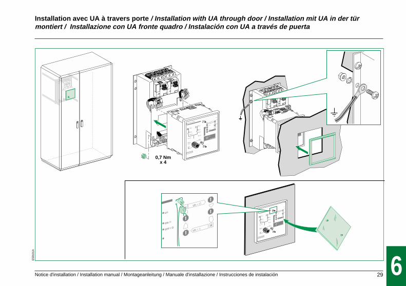
Installation avec UA à travers porte / Installation with UA through door / Installation mit UA in der türmontiert / Installazione con UA fronte quadro / Instalación con UA a través de puerta
29

Notice d'installation / Installation manual / Montageanleitung / Manuale d'installazione / Instrucciones de instalación
0 . OFF I . ON
test
CLAC !
5
NS100 V 6301
R
N
N
R
auto
stop
manu
UN
ON
OFF
fault
UR
ON
OFF
fault
UN = O
UN = 1
compact NSMERLIN GERIN
UA automatism
200/240V 50/60 Hz
N
R
test
com
stop generatort5 (s)
t2 (s)
t4 (s)t3 (s)
t1 (s)
R
N
NS630b V 1600NTNW
1
CLAC !
CLAC !
6
0 . OFF I . ON
test
CLAC !
40 . OFF
0 . OFF
I-ON
2
0 . OFF
0 . OFF
I-ON
3
R
N
N
R
auto
stop
manu
UN
ON
OFF
fault
UR
ON
OFF
fault
UN = O
UN = 1
compact NSMERLIN GERIN
UA automatism
200/240V 50/60 Hz
N
R
test
com
stop generatort5 (s)
t2 (s)
t4 (s)t3 (s)
t1 (s)
R
N
5
UN = 1 UR = 1 UN = 1 UR = 1
manu auto
2
stopmanu
auto
N R
4
I ON
O OFF
I ONO OFF
I ON
O OFF
stopmanu
auto
N R
3
I ON
O OFF
CLAC !
CLAC !
7E
5911
0A
Test de fonctionnement normal / Operating test / Test Normalbetrieb / Test di funzionamento normale /Test de funcionamiento normal
30

Notice d'installation / Installation manual / Montageanleitung / Manuale d'installazione / Instrucciones de instalación
R
0 . OFF
0 . OFF
I-ON
3
7
RESETN
NS630b 1600NTNW
UN = 1
UR = 1
CLIC !
CLIC !
R8
10
RESET
5N
1
2
stopmanu
auto
N R
4
stopmanu
auto
N R
6
stopmanu
auto
N R
9
R
N
7E59
111A
Test du verrouillage électrique sur défaut / Test on electrical locking following a fault
31
Les disjoncteurs nechangent pas d'état.No change in statusof circuit breakers
Les disjoncteurs nechangent pas d'état.No change in statusof circuit breakers

Notice d'installation / Installation manual / Montageanleitung / Manuale d'installazione / Instrucciones de instalación
R
0 . OFF
0 . OFF
I-ON
3
7
RESETN
NS630b 1600NTNW
UN = 1
UR = 1
CLIC !
CLIC !
R8
10
RESET
5N
1
2
stopmanu
auto
N R
4
stopmanu
auto
N R
6
stopmanu
auto
N R
9
R
N
Test verriegelung nach Fehler / Test dell'interblocco elettrico su guasto /Test de enclavamiento eléctrico por defecto
E70
655A
32
7
Keine Umschaltung.Gli interruttori noncambiano di stato.Los interruptoresautomáticos nocambian de estado
Keine Umschaltung.Gli interruttori noncambiano di stato.Los interruptoresautomáticos nocambian de estado

Notice d'installation / Installation manual / Montageanleitung / Manuale d'installazione / Instrucciones de instalación
1 2 3 4
N R
stopmanu
auto
UA Automatism
UN
fault
off
on
RN UR
fault
off
on
220/240 V 50/60Hz
N UN = 0
1525 10
2010,5 30
t4 (s)
812 4
150,50,1 30
t1 (s)
1525 10
2010,5 30
t3 (s)
60815 30
12040,1 240
t2 (s)RUN = I
360180240 300
48012060 600
t5 (s)
stop generator
RN
Compact / Masterpact
Test
BA
C
B=0B=1
N=offN=on
C=0C=1
t6=120st6=180s
EJP / voluntary transfer
fault generator
t maxstart generator
A=0 contrôle /N ou / to N or to control
/ voltage
24 N O L
N
0 1
R E 25
si contact ferméif contact closed
ordre depermutationvolontaire (ex: EJP)voluntary transfer
17 18 20 21
RNA=1 contrôle 3
3 control
switch C
switch B
8
Operating diagram
E59
094A
STANDBY
when the UAis de-energised,the "generatorstart-up order"
output isactivated.
Energisation
Non
Ron
Non
R on andUN present
Ron
Non
R on andUN absent
generatorstops
generatorstops
generatorstops
STANDBY
Ron
Non
Roff
Noff
Noff
Roff
ordersent
ordersent
ordersent
end of t4
end of t6
end of t3
URfault
t < t6 andUR present
order sent
and UR present
order sentand UR absent
R opens R opensN opens N opens
N closes R closes
reconnectiont4 &
reconnectiont3 &
load shedding
Four-positiion switch STOP/AUTO/R/N
Change modes by quickly turning selector switch from one position to another.Voluntary transfer (e.g. for energy management signals)An external signal can be used to initiate a transfer to "Replacement" source identical to transfer due to UN absent.The load returns to the "Normal" source when the signal is cleared in the same manner as a return transfer due to UN restored."Replacement" source voltage contact (controlled by an additional condition on the "Replacement" source)Transfert to "Replacement" source only if contact is closed (condition satisfied). This condition is not taken into account for return transfer to the "Normal" source.
(1) Penalties accepted (N on) : B = 1
35
The system leavesstandby mode
when the switch positionis changed (or when
an external event occurs,e.g. UN lost or restored).
UR present = . voltage present on source R.. Source R additional condition contact closed.
Go to indicated step.
generatorstarts
tempo t6(switch C)
stopmanu

Notice d'installation / Installation manual / Montageanleitung / Manuale d'installazione / Instrucciones de instalación
E59
894A
11
4
AUTO
15
TEST
324
2
11
5
1 3
5
(1)
test
Operating diagram
36
8Energisation
STANDBY
press
TEST mode* LEDsflashing
generatorstarts
order sentand UR absent
time delay t6(switch C)
generatorstops
order sent andUR present
time delay t6(switch C)
generatorstops
generatorstarts
t < t6 andUR present
t < t6 andUR present
end of t6
end of t3
end of t2
end of t4
end of t5
end of t1 end of t5
time delay t5time delay t1
N opens
R on
UR absentor end
of 180s
R closes
R opens
N opens
N opensN closes
loadshedding
R closes
N opens
UNpresent
UN absent &UR present
time delay t2
t4 &reconnection
t3 &disconnection
R off
time delay t5
UR fault and180s elapsed
N off N on
Normalstate
UNabsent
URpresent
UNpresent
N off
R on
end of t3
voluntary transfer
voluntary transfer mode
reconnection
R on
N off
R off
UR absent andUN present
ans B = 0
UR absent andUN presentand B =1
N on andvoluntary transfer
ordersent
generator stopschoice (switch B)
N off load shedding= 1
B = 0 B = 1
end of t6 andUR absent
*: Test duration
180 seconds
voluntarytransfer
STANDBY STANDBY STANDBY STANDBY
no voluntarytransfer
no voluntarytransfer
no voluntarytransfer
generatorstops
R closes N closes
end of t3
R opens
reconnection
generatorstarts
t3 &disconnection
t3 &disconnection

10-0151201113AA-A0
© 2
001
Sch
neid
er E
lect
ric S
A A
ll rig
hts
rese
rved
Schneider Electric Industries SA
5, rue Nadar92506 Rueil-Malmaison Cedex FranceTel : +33 (0)1 41 29 82 00Fax : +33 (0)1 47 51 80 20
http://www.schneiderelectric.com
Printed on recyclable paper.
Designed by: AMEGPrinted by: