
Integración de gasificación de biomasa en un proceso de...
111
0 Proyecto fin de carrera Ingeniero Químico Integración de gasificación de biomasa en un proceso de oxicombustión: análisis del estado del arte. Author: Juan Manuel Míguez Zambrano Director: Manuel Campoy Naranjo
Transcript of Integración de gasificación de biomasa en un proceso de...
0
Proyecto fin de carrera
Ingeniero Químico
Integración de gasificación de
biomasa en un proceso de
oxicombustión: análisis del estado
del arte.
Author: Juan Manuel Míguez Zambrano Director: Manuel Campoy Naranjo

0

Integration of a biomass gasifier in an oxyfuel pilot plant.
1
RESUMEN:
Es posible que, en el año 2013, el dióxido de carbón antropogénico sea una de
las causas del calentamiento global y es por ello que la comunidad científica, hoy en
día, aun trabaja en la mitigación de las emisiones de este compuesto a la atmosfera.
Para la mitigación de estas emisiones, la Unión Europea creó en 2005 los European
Union Allowances (EUA), un impuesto o tasa aplicada a las plantas que generan
dióxido de carbono por los cuales se les permite generar cierta cantidad de este
compuesto. Estos créditos o cesiones son una cierta cantidad económica que una planta
otorga al gobierno europeo para obtener el derecho de emitir una tonelada de dióxido de
carbono dependiendo de cuanto capital es capaz de pagar una empresa para obtener el
derecho. Según su situación económica, las empresas son capaces de otorgar al gobierno
una cantidad u otra pues los derechos son cedidos al mejor postor, es por ello que la
situación económica actual se ve reflejada en unos precios bajos para estos EUA.
Aun así, estos créditos son un incentivo para crear sistemas que mitiguen las emisiones
de dióxido de carbono, tal es el caso de algunas compañías que deciden diseñar sistemas
donde el dióxido de carbono sea consumido, obteniendo ellas mismas un beneficio ya
sea dado por el gobierno europeo o entidades privadas que deseen disminuir sus
emisiones pagando los derechos de emisión a estas plantas de emisión negativa.
La emisión negativa puede definirse como un proceso de generación de energía en el
que existe un consumo de dióxido de carbono siendo la emisión de este menor que su
consumo.
Para consumir dióxido de carbono de la atmosfera, una de las vías más interesantes es el
uso de la biomasa en diferentes procesos. Esta biomasa, al crecer, consume dióxido de
carbono de la atmosfera y, siempre que este dióxido no sea devuelto a la atmosfera,
cualquier proceso que use biomasa estará consumiendo dióxido de carbono de la
atmosfera.
Integration of a biomass gasifier in an oxyfuel pilot plant.
2
La biomasa puede definirse como material orgánico, tal como madera, desechos de
bosque, deshechos agrónomos, deshechos municipales o cualquier tipo de residuo o
deshecho orgánico usado como combustible o fuente de energía.
Esta biomasa incorpora dióxido de carbono de la atmosfera, generando compuestos
combustibles que generan energía que la propia biomasa ha obtenido de la luz solar.
Esta energía puede ser liberada mediante combustión, devolviendo a la atmosfera el
dióxido de carbono absorbido durante la vida de esta materia orgánica.
Tal y como se citó anteriormente, para generar un proceso de consumo de dióxido de
carbono es necesario que este no sea devuelto a la atmósfera, es por ello que es
necesario un sistema de captura y almacenamiento de dióxido de carbono para usar la
biomasa como clave para crear un sistema de emisiones negativas donde el dióxido de
carbono se consuma y no se emita.
Para que la biomasa genere energía ha de ser quemada, para ello se plantea en este
proyecto la posibilidad de usar biomasa sola o conjuntamente con otro combustible en
un proceso de oxicombustión donde la captura y el almacenamiento del dióxido de
carbono esta facilitada.
Debido al bajo poder calorífico de la biomasa y a que el combustible fósil más utilizado
a nivel industrial para la generación de potencia es el carbón, en este proyecto será
analizada la integración de la biomasa en un proceso con carbón.
Este proyecto analizara el estado del arte de una gasificación de biomasa integrada en
un proceso de oxicombustión en el que se pretende llegar a producir un sistema de
generación de potencia con emisión negativa.
Co-generación de biomasa y carbón:
La forma más efectiva de integrar el uso de biomasa y carbón en una misma
planta de generación de energía es la cogeneración. Esta cogeneración consiste en el uso
de un combustible alternativo en conjunto con un combustible principal con el objeto de

Integration of a biomass gasifier in an oxyfuel pilot plant.
3
obtener ciertos beneficios que el uso de un único combustible no conlleva por su propia
cuenta. En este caso el objeto es generar un proceso de emisión negativa.
Sin embargo, la cogeneración tiene múltiples vías de aplicación y estas han de ser
analizadas:
Cogeneración directa, donde la biomasa es insertada directamente en un horno y
quemada en conjunto con el carbón, esta es la opción más simple pero solo puede
utilizarse con ciertas biomasas ya que los materiales alcalinos de la biomasa provocan
corrosión en el proceso y en muchos casos han de ser tratadas previamente. Esta opción
requiere pocas modificaciones en la planta de carbón pero implica cierta falta de control
del proceso.
Cogeneración paralela, donde la biomasa es quemada en una cámara distinta al
carbón y genera vapor con otro sistema de intercambiadores ajeno a la planta de carbón,
sin embargo usan el mismo ciclo de vapor. Esta configuración es la que menos impacto
tiene en la planta de carbón y es la más cómoda a la hora de desactivar el proceso de
biomasa, sin embargo, resulta mucho más cara que las demás y el vapor que genera no
es de la misma calidad que el generado por la planta de carbón.
Cogeneración indirecta, donde la biomasa es gasificada con el objeto de ser
limpiada y evitar problemas de corrosión en la plata siendo el gas generado en el
proceso de gasificación el combustible que es usado luego en la caldera de carbón. Este
proceso tiene un coste intermedio comparado con los anteriores sin embargo posee una
característica muy interesante, es mucho más versátil. La versatilidad de este proceso
reside en la posibilidad de tratamientos intermedios entre la gasificación y el quemado
de la biomasa, adaptando el gas generado a las condiciones requeridas en la caldera.
La cogeneración indirecta parece la configuración más razonable a la hora de insertar
biomasa en un sistema de oxicombustión debido a los requisitos que implica un proceso
de combustión de carbón con oxígeno puro y no con aire. La oxicombustión necesita
bajas concentraciones de partículas en la caldera además de un control muy exhaustivo
de la temperatura en el interior, debido a la gran presencia de oxigeno y la variabilidad

Integration of a biomass gasifier in an oxyfuel pilot plant.
4
de la composición de los gases inertes en el interior. Estos gases provienen de un reciclo
de los propios gases de combustión de la caldera. Incluir un segundo combustible en el
proceso puede afectar considerablemente a este con lo que la existencia de la
posibilidad de adecuación intermedia entre gasificador y caldera es muy importante.
Siendo un sistema muy delicado, el objeto de este proyecto es producir un efecto
mínimo sobre el proceso de oxicombustión existente, es por ello que la versatilidad de
la cogeneración indirecta sea suficiente razón para elegirla como configuración óptima.
Gasificación de biomasa:
Debido a que la forma de integrar biomasa y oxicombustión elegida es la
cogeneración indirecta, es necesario para este proyecto realizar un análisis de
posibilidades a la hora de gasificar biomasa para esta planta de oxicombustión.
La gasificación esta definida como la conversión térmica de material orgánico a gases
combustibles bajo una atmósfera reductora con un agente o agentes gasificantes que
puede ser aire, oxigeno, vapor o dióxido de carbono.
El gas producido es una mezcla de monóxido de carbono, hidrogeno, dióxido de
carbono, vapor, nitrógeno, metano y otros hidrocarburos de bajo peso molecular, la
concentración de estos compuestos depende en los reductores usados, la biomasa
utilizada y las características del gasificador.
Debido a que el objeto de este proyecto es la integración de esa gasificación en un
proceso de oxycombustion, es interesante resaltar que todos los agentes reductores
posibles existen en este proceso de oxicombustión de antemano, tal como el oxigeno de
la unidad de separación de aire (ASU), el dióxido de carbono de los gases de
combustión del carbón, el vapor del sistema de turbinas y el aire del ambiente.
También es importante elegir sabiamente el gasificador a utilizar. El principal factor a la
hora de determinar el tipo de gasificador a utilizar es la potencia proporcionada, siendo
gasificadores de lecho fijo para unidades pequeñas (10 kWth-1 MWth), de lecho
Integration of a biomass gasifier in an oxyfuel pilot plant.
5
fluidizado para unidades intermedias (1 MWth a 100 MWth) y gasificadores de lecho
arrastrado para unidades grandes (>50 MWth).
Siendo el gasificador ideado de una potencia de 3 MWth, el modelo elegido será el de
lecho fluidizado. Este lecho puede ser a su vez burbujeante, circulante o de lechos
gemelos. Siendo el lecho circulante y los lechos gemelos sistemas aptos para altos
tiempos de residencia, deben ser descartados para el sistema analizado en este proyecto.
La biomasa utilizada será la más simple para este básico análisis del estado del arte, la
viruta de madera, en ingles woodchips, un tipo de biomasa que no necesita de grandes
tiempos de residencia para generar un gas con un poder calorífico aceptable. El tipo de
gasificador será un lecho fluidizado burbujeante.
Debido a que existe oxigeno, dióxido de carbono y vapor disponibles en la planta, serán
utilizados como agentes reductores del proceso descartándose el aire cuyo nitrógeno gas
no es deseable en la planta de oxicombustión. La cinética de este proceso es compleja y
poco conocida con lo que cualquier modelo no será suficientemente acertado como para
utilizarse en los cálculos, es necesario por lo tanto información empírica.
El departamento de Bioenergía de la Universidad de Sevilla, ha provisto para la
elaboración de este proyecto datos interesantes sobre un gasificador de 3 MWth que se
ajusta perfectamente al objeto de este proyecto. A su vez, este gasificador usa dióxido
de carbono y vapor como agentes gasificadores además de oxigeno como comburente
que consume biomasa para aportar energía al proceso manteniéndolo a 900ºC. El
gasificador usa 500 kg/h de viruta de madera para generar un gas de bajo poder
calorífico.
Analizando los datos provistos por el departamento de Bioenergía y comparando los
resultados de los experimentos llevados a cabo en el gasificador, cabe destacar la
complejidad del proceso. Tres compuestos principales son puestos en contacto con la
biomasa; vapor y dióxido de carbono como agentes gasificantes y oxigeno como
comburente. El vapor, a la hora de actuar como reductor, es mucho más efectivo y posee
una cinética más rápida que el dióxido de carbono, el dióxido de carbono, estando
Integration of a biomass gasifier in an oxyfuel pilot plant.
6
relacionado con reacciones más lentas, supone el paso controlador de la velocidad del
proceso. Ambos compuestos generan hidrógeno y monóxido de carbono, generando un
gas de síntesis diluido en dióxido y vapor el cual posteriormente se le llamara gas
producto o biomasa gasificada.
El vapor como agente gasificante genera más cantidad de hidrógeno mientras que el
dióxido de carbono genera más monóxido de carbono, siendo el primero un compuesto
con mayor poder calorífico que el segundo, la generación de hidrogeno prima sobre la
generación de monóxido de carbono.
El vapor y el dióxido de carbono en este proceso se insertan conjuntamente ya que
provienen de una desviación de los gases de salida de una supuesta planta de
oxicombustión.
Es también resaltable que la presencia de mayor cantidad de agentes gasificantes no
aumenta la eficiencia del proceso ya que el fenómeno de transporte controlador de la
reacción es la reacción de desorción y la reacción superficial. A mayor concentración de
agentes gasificantes se da una reducción de la eficiencia y la conversión de carbón en la
biomasa durante el proceso mientras que aumenta la relación hidrógeno/monóxido de
carbono debido a la mayor presencia de vapor en el proceso.
Es por ello que se plantea la posibilidad de la introducción al proceso de gasificación de
un aporte extra de vapor para aumentar la cantidad de hidrogeno generado sin reducir la
eficiencia del proceso ya que las cenizas generadas tendrían un contenido mayor en
carbón, contenido controlado por la legislación española y que requeriría nuevos
procesos de tratamiento de estas cenizas.
Este proceso genera un gas de síntesis disuelto con un poder calorífico inferior en el
rango de 7 a 10 MJ/Nm3.
Este gas de síntesis disuelto es introducido posteriormente en una caldera con lo que el
objetivo mayor de este gas es poseer el máximo poder calorífico posible pero también
ha de ser resaltado que las cenizas producidas pueden acarrear problemas por tener gran
Integration of a biomass gasifier in an oxyfuel pilot plant.
7
contenido en carbono según la legislación vigente. Es por ello que también es un factor
a considerar una mayor conversión del carbón o un subproceso de tratamiento de las
cenizas.
Proceso de oxicombustión:
La oxicombustión puede definirse como un proceso de generación de energía
combinado con captura y almacenamiento de dióxido de carbono donde un combustible
es quemado en presencia de oxigeno puro en una cámara de combustión disuelto con un
gas compuesto principalmente por dióxido de carbono proveniente de la recirculación
del gas de salida de la caldera, generando energía y unos gases de combustión
compuestos casi en su totalidad por dióxido de carbono facilitando su posterior captura.
Este proceso se puede instalar en centrales de carbón ya construidas con un descenso del
rendimiento de un 9 % y una inversión mediana. Siendo un proceso de emisión cero
donde todo el dióxido de carbono generado se captura y almacena, es posible
convertirlo en un proceso de emisión negativa si se combina con la cogeneración con
biomasa anteriormente citada.
Las variables clave en este proceso son la pirolisis y la combustión del char de carbón,
en este proceso está probado que la generación de volátiles de carbón es mayor para
atmosferas ricas en dióxido de carbono que en atmosferas ricas en nitrógeno como
ocurre en las centrales de carbón que usan aire como comburente, además, el dióxido de
carbono mejora la especiación de estos volátiles. La caracterización de la llama es otro
de los factores clave, la oxicombustión acarrea problemas de retraso en la ignición de la
llama, problemas que han de ser resueltos con una optimización de la relación dióxido
de carbono/oxigeno hallada en la cámara de combustión, siendo esta optima con
concentraciones de oxigeno en torno al 30%.
Otro factor clave son las emisiones de compuestos contaminantes como los NOx y el
SO2. Al existir una recirculación de los gases de combustión en el proceso, estos
compuestos son descompuestos en la llama la cual alcanza temperaturas en torno a los
1300ºC, con lo que la generación de estos compuestos disminuye si se compara con una

Integration of a biomass gasifier in an oxyfuel pilot plant.
8
planta que usa aire para la combustión de carbón. Sin embargo, la generación de
compuestos como HCN, NH3 y SO3 aumentan debido a la gran presencia de oxigeno en
la combustión, la escasez de nitrógeno gas y las altas temperaturas alcanzadas en la
llama. Estos compuestos generan problemas de corrosión en la cámara de combustión,
que se incrementan con la gran presencia de dióxido de carbono, y es por ello que los
materiales usados deben ser analizados con detenimiento.
Como último factor clave para el diseño de este tipo de plantas, han de ser citados los
problemas que acarrea la deposición de la ceniza en el interior de este proceso, esta
deposición provoca problemas de slagging y fouling, que han de ser solventados con
una meticulosa limpieza de las partículas presentes en los gases de combustión que son
recirculados a la cámara de combustión.
Para un mejor visionado de los efectos de esta integración, este proyecto ha elegido
como ejemplo la planta de Vattenfall llamada Schwarze Pumpe, una planta piloto erecta
en Alemania. Esta planta piloto es una planta de oxicombustión de 30 MWth, el objeto
de este proyecto es sustituir 3 de esos 30 MWth por potencia generada por la
combustión de una biomasa gasificada generada en gasificador diseñado por el
departamento de bioenergía de la universidad de Sevilla anteriormente citado.
Esta planta se compone de una unidad de separación de aire (ASU) que genera un
oxigeno de alta pureza (99.5%) que se inserta en una cámara de combustión junto con
carbón lignito y el reciclo de los gases de combustión.
Tras la combustión del carbón y el paso de los gases de combustión por los
intercambiadores pertenecientes al ciclo de vapor, que aun no está diseñado para
generar potencia en una turbina, existen varios procesos de limpieza de estos gases de
salida. El primer proceso debía ser un proceso De-NOx para eliminar los NOx generados
en la combustión, pero estos NOx tienen una concentración no muy elevada con lo que
aun esta unidad no ha sido diseñada por Vattenfall. Consecuentemente, el primer
proceso, ya construido, para la limpieza de estos gases es un precipitador electrostático,
con una eficiencia en torno al 99.93%. Posteriormente la planta recircula los gases de
Integration of a biomass gasifier in an oxyfuel pilot plant.
9
salida siendo la recirculación en torno al 70%. Tras la recirculación los gases del reciclo
secundario se introducen en la cámara donde un quemador Hitachi DTS-Burner se
encarga de mezclar las corrientes de reciclo, oxigeno y carbón pulverizado, y también
de encender la llama que prende la mezcla.
Los gases que no son recirculados son desulfurados y el vapor presente es condensado
en sendas unidades de desulfuración y condensación. El gas restante es un dióxido de
carbono con una pureza del 95% que es redirigido al proceso de captura y
almacenamiento, aunque una parte de ese forma un reciclo primario que pone en
circulación el carbón pulverizado.
Integración de los procesos:
Como anteriormente ha sido expuesto, este proyecto analiza la posibilidad de
incluir un proceso de gasificación de biomasa en una planta de oxicombustión. Ha sido
también establecido que el proceso de gasificación aportaría un 10% de de la potencia
total de la planta la cual es 30 MWth. Esta sustitución se hace en conceptos energéticos
con lo que el carbón sustituido por biomasa será de un 7% del total de lignito (5t/h) que
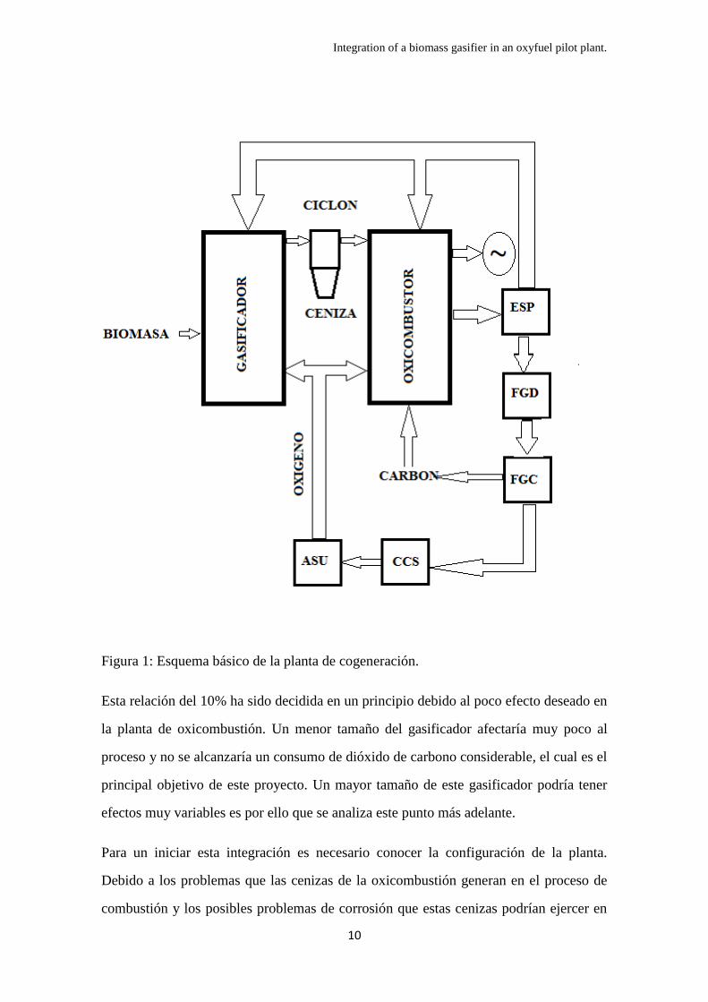
la planta de Schwarze Pumpe usa. El sistema se organizaría de la manera indicada en la
figura 1.
Integration of a biomass gasifier in an oxyfuel pilot plant.
10
Figura 1: Esquema básico de la planta de cogeneración.
Esta relación del 10% ha sido decidida en un principio debido al poco efecto deseado en
la planta de oxicombustión. Un menor tamaño del gasificador afectaría muy poco al
proceso y no se alcanzaría un consumo de dióxido de carbono considerable, el cual es el
principal objetivo de este proyecto. Un mayor tamaño de este gasificador podría tener
efectos muy variables es por ello que se analiza este punto más adelante.
Para un iniciar esta integración es necesario conocer la configuración de la planta.
Debido a los problemas que las cenizas de la oxicombustión generan en el proceso de
combustión y los posibles problemas de corrosión que estas cenizas podrían ejercer en

Integration of a biomass gasifier in an oxyfuel pilot plant.
11
el gasificador, ha sido decidido que la corriente de gases de combustión que alimentara
el gasificador de agentes gasificantes ha de extraerse tras el separador electrostático de
la planta de oxicombustión.
Puesto que los compuestos sulfurados tienen un efecto mínimo en el reciclo de la
oxicombustión y que la presencia de vapor no afecta en demasía el buen funcionamiento
de la caldera, la planta de oxicombustión recircula también en ese mismo punto un
reciclo secundario. El vapor que se halla en la recirculación debido a la ausencia de
condensación del vapor mejora el proceso de gasificación con lo que es deseable, sin
embargo, no es conocido el efecto de los compuestos sulfurados en el proceso de
gasificación con lo que un análisis más a fondo en este área podría cambiar la
colocación de la extracción de gases de combustión.
En la elección de la posición de la extracción de gases de combustión que alimenta el
gasificador ha primado la temperatura de la corriente, la cual mejora el poder calorífico
del gas generado en este gasificador gracias a un menor uso de oxigeno para mantener
la temperatura a 900ºC, es por ello que por defecto se plantea una extracción tras el
separador electrostático donde los gases poseen una temperatura de 180ºC.
La generación de compuestos sulfurados y nitrogenados en la gasificación es baja
comparada con la presencia de estos compuestos generados por el carbón con lo que
procesos de limpieza de estos entre la salida del gasificador y la entrada a la cámara de
combustión en este campo son eliminados. Sin embargo, la generación de partículas de
ceniza volátil en el gasificador es alta comparada con la presencia de estas en la cámara
(5mg/Nm3). Es por ello que se recomienda un método de limpieza en caliente previo a
la inserción de este gas en la cámara de combustión.
Este proceso de limpieza ha de ser un proceso en caliente para no condensar los
alquitranes presentes en la biomasa gasificada los cuales tienen poder calorífico y son
interesantes para aumentar el calor generado en la caldera. Es por ello que inicialmente
se recomienda el uso de un ciclón intermedio entre la gasificación y la combustión.
Otros tipos de biomasa o una mayor relación biomasa/carbón en la planta generaría altas

Integration of a biomass gasifier in an oxyfuel pilot plant.
12
concentraciones de partículas indeseables en la cámara de combustión con lo que se
recomienda un filtro cerámico para la limpieza de estas.
En caso de usar un aporte extra de vapor al gasificador, ha sido calculado el efecto de
una extracción de vapor en el ciclo de potencia de la planta (aun inexistente en
Schwarze Pumpe). Este ciclo fue ideado básicamente y ha sido planteada una
extracción entre los sangrados de la turbina o en la salida de vapor de esta. No se
considera la opción de extraer vapor directamente de la salida de los intercambiadores
pues reduciría la eficiencia del proceso y puesto que esta extracción se realizaría para
aumentar esta eficiencia se trata de una opción descartable. El efecto de esta extracción
sobre los economizadores de la planta fue calculado y se trata de un efecto despreciable
si se compara el calor que este vapor puede aportar a la integración energética de la
planta con la capacidad que este aporte extra de vapor tiene para generar gas de síntesis
en el gasificador. El total de energía perdido es mucho menor que la energía potencial
generada al generar más hidrogeno en la gasificación. Sin embargo, debido a la
complejidad de este proceso ha sido supuesto que esta extracción de vapor no se realiza
para los cálculos posteriores.
También fue calculado el efecto de esta integración del 10% en potencia en el balance
de masa de las corrientes. Puede ser establecido que el efecto es ínfimo en la planta y no
es necesario un rediseño o reajuste del tamaño de la planta de oxicombustión,
abaratando en gran medida la integración de la gasificación en la oxicombustión.
Sin embargo, aun siendo los efectos en balances de masa poco significativos y siendo
solo necesario un ciclón para adecuar el gas generado en la gasificación a la caldera, el
propio comportamiento de la combustión dentro de esta caldera puede variar pues está
siendo introducido en ella un combustible distinto al carbón.
Debido a la gran diferencia entre los dos combustibles es necesario el diseño de otro
quemador para esta biomasa gasificada. Aun siendo un gas de síntesis diluido en
dióxido de carbono y vapor es necesario un aporte extra de gases inertes para mantener
la llama de este gas a 1350ºC, siendo esta la temperatura de combustión del carbón en la

Integration of a biomass gasifier in an oxyfuel pilot plant.
13
caldera. El gas de síntesis al quemarse puede alcanzar temperaturas de 2000ºC y mayor
aun en condiciones de oxicombustión con lo que el diseño de este quemador es clave a
la hora de maximizar la eficiencia del proceso.
El comportamiento de la llama de la combustión de la biomasa gasificada depende de su
relación hidrogeno/monóxido de carbono, también la cantidad de dióxido con la que es
mezclada en el quemador define la velocidad de la llama y su temperatura,
empeorándolas, y, por supuesto, la temperatura a la que es insertada esta biomasa
gasificada aumenta la velocidad de llama y la eficiencia del proceso con lo que la
temperatura a la que se inserta, que depende de la temperatura del reciclo especifico
para la biomasa y la temperatura de salida del gasificador, debe ser tomada en cuenta a
la hora de maximizar la eficiencia del proceso.
La cantidad de alquitrán en esta biomasa gasificada afecta mínimamente al
comportamiento de la llama pero aun así su presencia es deseable pues aumenta la
energía generada. Sin embargo, una gran presencia de vapor desciende la velocidad de
esta llama afectando negativamente a su combustión, por el contrario, una gran
presencia de hidrogeno aumenta esta velocidad. Es necesaria una investigación más a
fondo sobre el comportamiento de una llama de biomasa gasificada en estas condiciones
para diseñar el proceso.
Tras un primer análisis de los efectos de una integración al 10% en potencia, fue
analizado el efecto de escalado de la unidad de gasificación en esta supuesta planta. Los
resultados indican que para una mayor relación biomasa/carbón en esta cogeneración, la
cantidad de dióxido consumido aumenta, lógicamente pues es usada más biomasa,
mientras que la cantidad total de dióxido de carbono para una misma potencia generada
se mantiene estable cuando aumenta la relación biomasa/carbón.
Al aumentar el tamaño del gasificador, la cantidad de SO2 total generada disminuye
causando un menor trabajo de la unidad de desulfuración mientras que aumenta la
cantidad total de vapor generado y que ha de ser eliminado previa captura del dióxido
de carbono, aumentando el trabajo del condensador.
Integration of a biomass gasifier in an oxyfuel pilot plant.
14
Sin embargo una alta relación de biomasa/carbón provoca la necesidad de una unidad
De-NOx y que la cantidad de compuestos nitrogenados aumenta considerablemente,
además, la cantidad de partículas introducidas en la caldera aumenta hasta el punto que
es necesario un filtro cerámico para poder introducir la biomasa gasificada en la caldera.
Los valores de reciclo de gases de combustión y el oxigeno requerido para el
funcionamiento de la planta aumentan con la relación biomasa/carbón.
Los cálculos realizados en el escalado del gasificador son poco fiables para altas
relaciones biomasa/carbón, esta poca fiabilidad proviene de los grandes cambios que
una alta relación de estos dos combustibles provoca en el gas de combustión de la
caldera. Al existir una mayor cantidad de vapor y menor proporción de dióxido de
carbono es posible que la propia combustión en el oxicombustor varie gravemente
debido al elevado calor especifico del vapor que lentificara la llama y, probablemente,
la eficiencia de la combustión. Ademas, este mismo gas de combustión es el gas usado
para gasificar la biomasa, la gran cantidad de vapor y la menor cantidad de dióxido de
carbono, mejoraría la eficiencia de la gasificación pero el incremento del calor total
aportado pro la biomasa está limitado al 2% del calor total aportado con una relación
biomasa/carbón del 10%. Esto se debe a la alta conversión que el gasificador diseñado
por el departamento de bioenergía de la universidad de Sevilla posee.
Se puede concluir que existe un punto optimo en la relación biomasa/carbón mayor al
10% en potencia con lo que un análisis de proporcionalidad idónea ha de ser realizado si
un experimento empírico es llevado a cabo.
Finalmente se realizo un balance del dióxido de carbono en la planta. El objeto de este
proyecto era crear un sistema de emisión negativa de dióxido de carbono y, aun siendo
viable y posible con la tecnología actual y con experimentos de no demasiada
complejidad, no parece beneficioso a día de hoy realizar esta integración. La causa
principal es la generación de dióxido de carbono de la biomasa. Ignorando que en
relación al carbón, la emisión de dióxido de carbono es cero, en relación a la biomasa el
objeto principal de este proyecto era encontrar una opción donde el coste de la captura
de dióxido de carbono generado por la gasificación y combustión de la biomasa (20-

Integration of a biomass gasifier in an oxyfuel pilot plant.
15
25€/ton) sea menor que el potencial beneficio de la venta de derechos de emisión por el
consumo de dióxido de carbono de la atmosfera. Estando los EUA hoy en día a un
precio en torno a los 10 €/ton de dióxido de carbono y considerando que la venta de
derechos ha de tener un precio menor a este para que otras empresas compren ese
derecho a esta planta se puede asumir que esta integración no aporta beneficios
indiferentemente de la relación biomasa/carbón que exista en esta cogeneración. Sin
embargo un aumento en el precio de los EUA hasta una cifra mayor que el coste de la
propia captura generaría beneficios con lo cual, hoy en día no es aplicable, sin embargo
en un futuro es más que probable que esta integración sea beneficiosa.

Integration of a biomass gasifier in an oxyfuel pilot plant.
16
ABSTRACT:
Biomass and oxycombustion of coal are combined in the analysis given in this
project. The way of combine these processes is the indirect co-firing, using a bubbling
fluidized bed to generate a gasified biomass that is later on inserted in a boiler. This
boiler will use the gasified biomass and coal under oxyfuel combustion in order to
generate power. The flue gas produced by the combustion of these two fuels is
composed mainly in carbon dioxide and captured and storage.
This project is a state of the art analysis and it explains the way to follow at the time of
researching most of the investigations required previous to the creation of an actual
plant using this technology. All variables and possibilities regarding this technology are
investigated and the most important recommendations are given in the following pages.
Possible configurations, kinetics of the process, contaminant component control,
limitations, advantages of the implementation and effect of biomass/coal rate are
investigated.
The main porpoise of this project is to generate a system that consumes carbon dioxide
from environment, generates power and is economically viable. The two firsts porpoises
are achieved but it is not still economically viable the construction of an indirect co-
firing plant using biomass and coal under oxyfuel conditions. The reason is the low
prices of European Union Allowances which values today are marked by economical
crisis. It is necessary a better economical conditions, a higher price on coal and a lower
price on biomass to have a viable environment for this technology without considering
other kind of incentives.

Integration of a biomass gasifier in an oxyfuel pilot plant.
17
INDEX:
Resumen 1
Abstract 16
Chapter 1: Introduction 18
1.1 Introduction and scope 18
1.2 Motivation and objective 21
1.3 Structure of the project 22
Chapter 2: State of art 24
2.1 Co-firing status 28
2.2 Biomass gasification status 29
2.3 Carbon capture and storage status 32
Chapter 3: technology analysis 35
3.1 Gasifier technology 35
3.2 Bubbling fluidized bed gasifier: Mechanics and kinetics 40
3.3 Oxyfuel combustion 51
3.4 Vattenfall Schwarze Pumpe plant 57
Chapter 4: Integration of a biomass gasification process in an oxyfuel pilot plant 63
4.1 General aspects of the integration 63
4.2 Flue gas stream situation 65
4.3 Steam stream situation 73
4.4 Effect of using product gas in the furnace 76
4.5 Gasifier scale up 89
CHAPTER 5: Summary and conclusions 95
Illustrative tables 100
References 102
Integration of a biomass gasifier in an oxyfuel pilot plant.
18
CHAPTER 1 Introduction.
1.1 Introduction and scope.
In 2013 it is still possible that anthropogenic CO2 could be one of the causes of
climate change and scientific community is still investigating the mitigation of the
emissions of this compound to atmosphere.
In 2009, European commission settled the basis of the European Union (EU) climate
package of the called “20/20/20” with the EU Directive 2009/28/CE. To reduce
emissions of greenhouse gases a total of 20 %, increasing by 20% energy generation
from renewable sources and reduce energy consumption by 20%, was the main idea of
this project, all of this with 2020 as deadline and comparing the values with the
situation in 1990. Reducing the global temperature growth to a maximum of 2ºC is not
an easy task, this task was assumed by this EU directive and every new line of
investigations is always interesting.
But the price of reaching this objective is considerably high, EU commission has
estimated costs around €70 billion per year in order to reach this 20% target and it has
stated that the objective in 2010 had fell but still new objectives will appear and
investigation must not stop. [1]
Since 2005, when European Union emission trading scheme was created, carbon credits
have become an interesting commodity and also resource usable in European market.
These also called EUA (European Union Allowances), referred to the surrendered
capital to this scheme for each ton of CO2 or ton of gas equivalent emitted between each
April month of each year. The cost of each emitted ton varies depending on the market
and the economical status of the European Union, also counting that the effect of the
world economics is not despicable.
The creation of CER’s (Certified Emission Reduction) by the Clean Development
Mechanism (CDM) with the Kyoto protocol meant a way to help new technologies that
still could not receive revenue from EUA credits. These credits are economical helps
carried out by states or private enterprises for new technologies that can reduce CO2
emissions and have large relation with creating a market willing on reduce them.

Integration of a biomass gasifier in an oxyfuel pilot plant.
19
But the price of EUA and CER does not have a fixed value. Depending on the world
economics this value may change, and the size of its market also depends on it. Today’s
financial crisis is affecting the price of these allowances, and it is marking the direction
of renewable energy sources investigation. [2]
Prices of EUAs are determined using the ratio between the costs of CO2 emissions
saving (supply) and the costs of the emission level (demand) in the various industry
sectors. The objective of emissions trading is to realize emissions reductions where they
are most cost-effective. [3]
These credits are influenced by many factors as political decisions, economic growth,
fuel prices, banking, trading strategies, new technologies, state-supported purchase
schemes, new industry sectors or new type of gases. All these factors make really
difficult the prediction of the EUA price or CER helps. Figure 1 shows nevertheless that
prices of EUA, CER, oil, coal and electricity are well related [4].
Figure 1: Correlation between EUA, CER, Oil, Gas, Coal and Elecrtricity prices [4]
This proves that, in case of fossil fuel price increases, new technologies related with
emission reduction will be much more interesting in today’s context.
Integration of a biomass gasifier in an oxyfuel pilot plant.
20
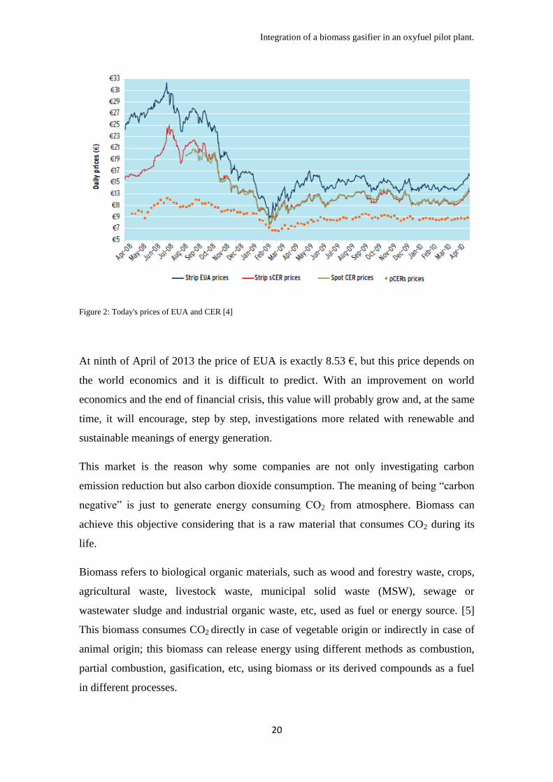
Figure 2: Today's prices of EUA and CER [4]
At ninth of April of 2013 the price of EUA is exactly 8.53 €, but this price depends on
the world economics and it is difficult to predict. With an improvement on world
economics and the end of financial crisis, this value will probably grow and, at the same
time, it will encourage, step by step, investigations more related with renewable and
sustainable meanings of energy generation.
This market is the reason why some companies are not only investigating carbon
emission reduction but also carbon dioxide consumption. The meaning of being “carbon
negative” is just to generate energy consuming CO2 from atmosphere. Biomass can
achieve this objective considering that is a raw material that consumes CO2 during its
life.
Biomass refers to biological organic materials, such as wood and forestry waste, crops,
agricultural waste, livestock waste, municipal solid waste (MSW), sewage or
wastewater sludge and industrial organic waste, etc, used as fuel or energy source. [5]
This biomass consumes CO2 directly in case of vegetable origin or indirectly in case of
animal origin; this biomass can release energy using different methods as combustion,
partial combustion, gasification, etc, using biomass or its derived compounds as a fuel
in different processes.

Integration of a biomass gasifier in an oxyfuel pilot plant.
21
Biomass generally provides four routes for carbon mitigation: in situ sequestration by
reforestation and conservation; remote sequestration by harvest and burial; substitution
for fossil fuels; and substitution for fossil fuels with remote sequestration [6].
But biomass combustion generates CO2 also while being burn, a way to consume this
CO2 and not to emit it is the Carbon Capture and Storage technology (CCS).
Carbon Capture and Storage is a technology developed in the latest years where the
carbon dioxide produced in combustion of a fuel is collected and storage underground,
this results in zero emission of carbon dioxide and is a safe method that can be applied
directly in the meanings of energy generation existent today.
Summarizing, using biomass combined with CCS it is possible to reach two of the three
points on the 20/20/20 targets, reducing emissions and generating energy from a
renewable resource.
The most viable idea is to use biomass in an existing boiler, but this boiler, in order to
facilitate the CCS should be an oxyfuel plant, a fossil fuel combustion process using as
comburant pure oxygen. The way to implement biomass in an oxyfuel plant is co-firing,
one of the most studied technologies in order to avoid carbon dioxide emissions.
1.2 Motivation and objective.
Two new technologies are being studied all around the world, oxyfuel
combustion and biomass gasification. This project tries to introduce the reader into
these two technologies and creates a possible environment where those technologies can
be integrated one on the other.
There exists a special motivation on this project due to its limitations, it has to be noted
that most of the studies and investigations quoted in the following pages are not
developed in an industrial environment making the elaboration of this project a
challenge itself being useful for me due to the experience that I will receive in order to
face new challenges like this in the future.
The aim of this project is to facilitate future investigations in the area of co-firing
gasified biomass in an oxyfuel plant. This project is willing to find the different areas

Integration of a biomass gasifier in an oxyfuel pilot plant.
22
where investigation is required in order to create a viable system for this technology.
Previous investigations will be analyzed, status of the technology will be investigated,
all possible configurations will be examined and all variables will be studied. The final
objective of this project is to create a basic configuration of an integration of a biomass
gasifier into an oxyfuel plant and preliminary results will be shown.
1.3 Structure of the project.
This project will be divided in five chapters. Chapter one, in previous pages,
exhibited the different reasons leading to the process that later on will be analyzed. This
chapter describes basic definitions of EUA and CER and the situation that those credits
are suffering today; defines biomass and its characteristics and also states the
gasification of that biomass; defines co-firing of different fuels; and clarify the
definition of oxycombustion and carbon capture and storage. This point also declares
the motivation and objective of the project concluding that this project will analyze the
co-firing of a gasified biomass in an oxyboiler.
Chapter two is a state-of-art analysis, this analysis will involve the three stages of the
process that this project treats about, co-firing, biomass gasification and carbon capture
and storage. This chapter encompasses the definition of co-firing, states the different
existing types of co-firing, its application worldwide and investigates which co-firing is
the most applicable for this project. In this chapter is concluded that indirect co-firing,
where gasification of biomass and combustion are integrated, arouses enough interest to
dedicate this project to it. In order to understand indirect co-firing, biomass gasification
is defined and characterized in this chapter in order to provide a general idea of the
process. Finishing the chapter a general analysis of carbon capture and storage is given.
This analysis concludes that oxycombustion is the most viable option at the time of
integrating carbon capture into a biomass/coal co-firing process.
Chapter three analyzes in dept the technology involved in the process treated in this
project. Biomass gasification technology is analyzed, different gasifier options are
shown, mechanics and kinetics of the gasifier chosen are explained and variables
involved are investigated. A theoretical gasifier already analyzed in [22] is explained.
Oxyfuel technology is also analyzed in this chapter, due to the fact that that oxyfuel

Integration of a biomass gasifier in an oxyfuel pilot plant.
23
process involves combustion and CCS, this technology is defined and explained in this
chapter, mechanics and characteristics of this technology are shown and different key
properties of the process useful for its design are stated. An example of this kind of
technology is described because it will be used later on for further calculations.
Chapter four describes a possible integration of a biomass gasification process into an
oxyfuel pilot plant, these two processes were explained in chapter three, and the effect
in both processes of this integration is analyzed in this chapter. Configuration of the
integration is analyzed and first conclusions are shown, analysis of different compounds
with remarkable importance is done, possible mass and energy balances are provided
and all variables are studied. Concluding the chapter, an analysis of a possible scale up
of the gasification process is studied.
Chapter five gather all the conclusions that the investigation made in this project lead to.

Integration of a biomass gasifier in an oxyfuel pilot plant.
24
CHAPTER 2: State of art.
2.1 Co-firing status.
The way to combine biomass and CCS from a coal power generation system is
the called co-firing. Co-firing is a technology that correlates use of two different fuels in
order to generate power. Two interesting fuels to combine, as it was explained before,
are biomass and fossil fuels. The energy produced in a co-firing process is dedicated to
heat up water to produced overheated steam. This overheated steam could generate
power using a turbine.
This technology is mainly applied in coal power plants but it has to be considered that
natural gas and oil are also a way to combine this biomass. Due to the high number of
coal power plants in the world and the applicability of this technology, the most viable
idea is to analyze biomass and coal co-firing.
Considering coal as the most used fossil fuel in commercial energy generation being
close to the 70% of total energy produced in Europe [7], co-firing is an option
nowadays very interesting.
Co-firing, the practice of supplementing a base fuel with a dissimilar fuel, is an
extension of fuel blending practices common to the solid fuels community. Today, co-
firing is viewed as the most cost-effective approach to biomass utilization by the electric
utility system [8]. Originally, co-firing was started to be used in the decade of 1980,
used by coal power plants that decided to introduce other fuels, like biomass or waste
solid residues, in boilers that were originally dedicated for burning only coal.
In the last ten years, with the global warming issue and the willing of companies of
reducing emissions of greenhouse gases (GHG), this technology has been beneficiary of
multiple investments due to its capacity of reducing these emissions in an already
existing plant. When applying co-firing some advantages can be assumed:
Co-firing of biomass could reduce NOx, SOx and heavy metals production
depending on the biomass used and that could conduce to governmental
incentives.
The neutral or negative CO2 process in co-firing could call for financial
incentives consequence of greenhouse gasses emission reduction.

Integration of a biomass gasifier in an oxyfuel pilot plant.
25
Biomass co-firing is an on-demand power production, that means, that is
available continuously not intermittent as other renewable energy resources, as
wind energy or solar energy. That conducts to accelerate payoff of the initial
investment for a higher capacity factor.
Co-firing of biomass is applicable to any coal fired plant, that means that the
implementation of this technology has lower opportunity cost.
Earning of renewable energy tax credits is a possibility that could accelerate the
implementation of this technology in existing plants.
Biomass price does not depend, in a first view, on coal price. Co-firing is also a
way of energy independence.
But there exists three ways of implementing co-firing in an existent coal power plant,
depending on the requirements of the plant and the possibilities that the secondary fuel
can offer, different configurations can be found:
Direct co-firing:
Direct co-firing consists in the direct feeding of a prepared biomass into the coal
boiler of a coal power generation process. This process is nowadays the most common
process at the time of producing electricity using, partly, biomass as fuel [9]. This
option does not require direct injection of biomass into the boiler, biomass can be also
mixed with the coal previously and later be introduced into the burning process, but this
configuration is limited to a few kind of biomass due to effects of alkali agglomeration
and corrosion in the boiler. When biomass is not premixed with coal and is introduced
directly into the boiler, the re-configuration requires only a small modification of the
boiler case. Otherwise, this configuration requires extra equipment and its consequent
cost, that, combined with the lack of control that this process involves, it entails that this
option is not widely used within coal power plants. Some industries have applied a
separation in the furnace itself, creating a first stage of pulverization and burning of
biomass where afterwards coal is added [8]. This improves the burning process to high
efficiencies but the total investment that an already build boiler needs for applying this
option is really high. As a last option, biomass can be used as a re-burning fuel for NOx
control, but even with a low operational risk, the investment is still high [10].
Integration of a biomass gasifier in an oxyfuel pilot plant.
26
Parallel or external co-firing:
Parallel co-firing consists in the creation of a totally different boiler just for
burning the biomass. This boiler, as the coal boiler, will produce steam, but in this case
with lower grade, that is afterwards utilized in the steam cycle of the coal power plant
for power generation. The flue gas produced in this process does not make any contact
with heat exchangers in the coal boiler, so it avoids corrosion and fouling problems on
it, but still these problems appear in the heat exchangers existent in the biomass boiler.
This option is not accompanied with a high risk, because it consists in a totally
separated unit, also, it has to be mentioned, that it is very reliable but does not provide
the efficiency that other options could provide meaning that is really far away from
being a profitable option still. Being a not really promising option, many enterprises do
not invest in this technology. [10]
Gasification or indirect co-firing:
Indirect co-firing is a promising configuration consisting in a gasification
process that gasifies biomass and produces a diluted syngas or product gas (low heating
value gas) that is later fed into the coal boiler. This process is extremely flexible and
many different improvements can be made over it. In this process there is a cleaning
stage between the gasification unit and the boiler making the process flexible, also there
exists a minimal production of NOx and the by-products produced in the gasification
stage can also improve the combustion in the boiler. Indirect co-firing requires an
intermediate investment, but is still promising for a multifuel option, being possible to
use it in a variable biomass feeding environment [10].
As three examples the 137 MWe Zeltweg Power Plant in Styria in Austria, the
AMERGAS biomass gasification project at the Amer Power Plant in Geertruidenberg,
Holland, and the Kymiarvi power station at Lathi in Finland, have applied this
technology in their respective industries, in some cases successfully as in Lathi, in other
as a failure as in Geertruidenberg.
Co-firing of biomass is being investigated all around the world, as it is shown in figure
3, and the election of a co-firing dedicated in an existing boiler is complicated due to the
similarities on the effect of implementing each one, table 1 shows an interesting
comparison in similar environments where this statement can be checked out.

Integration of a biomass gasifier in an oxyfuel pilot plant.
27
Figure 3: Co-firing plants around the world [11]
Some authors [12][9][10] have
established that biomass-coal co-
firing means reducing CO2 and
SO2 emissions and it may also
reduce NOx emissions and
represents a near-term, low-risk,
low-cost and sustainable energy
development. Biomass-coal co-
firing is the most effective
measure to reduce CO2 emissions,
because it is the substitution of coal (which represents the most intensive CO2 emissions
per kWh of electricity production) by biomass with zero net emission of CO2 [12].
Table 1 Comparison of the three different co-firing options in a comparable environment with same input [11].
Even with all the different kinds of biomass and, as it has been explained, the three
different ways of producing energy from biomass gasification, still direct co-firing from
woodchips is the most common process.

Integration of a biomass gasifier in an oxyfuel pilot plant.
28
If biomass co-firing were installed in only 1% of the total coal fired power plants
worldwide, the electricity produced directly with biomass would be 8GWe saving up to
60MTon of CO2 emitted to the atmosphere. At 2010 a total of 228 [13] different coal
fired power plants are using any kind biomass co-firing technology.
Specifically in Europe, many energy enterprises have successfully installed biomass co-
firing technology in existing coal fired power plants, with, in some cases, excellent
results.
The technology of direct co-firing has been implement, for example, in St. Andrä in
Austria, indirect co-firing in Zeltweg (Austria) or in Lahti (Finland), and Parallel co-
firing, even not being so common, has been installed in Ensted power plant in Denmark.
Al-mansour et al. [12] made an evaluation, considering different points of view, of the
existing technologies regarding co-firing of biomass. Rating from 1 to 3 each of the
following points, they found out surprising results:
Environmental impact as an indicator of the pollutant emissions that the
implementation of the technology carries out. One point was given if emission
parameters deteriorated after the implementation of the technology; two points if
emissions did not change or only CO2 and SO2 were reduced due to biomass
combustion; three points were given for the reduction of NOx emission.
Applicability as an indicator that defines the ease of technology application to
newly built as well as existing installations (retrofit). One point was given to
relatively complex technical solutions that require modifications of the furnace;
two points to relatively complex solutions that do not require modifications of
the furnace.
Operational experience as an indicator that defines the level of operational
experience for every group of technologies. One point was given to technologies
that have been tested experimentally or have only few industrial applications;
three points were given to technologies that have been very widely used in
industry.
Efficiency as an indicator that defines the impact of co-firing on general process
efficiency. One point was given for negative impact on boiler efficiency; two
points were given if an installation was neutral as regards boiler efficiency; three
points were given if boiler efficiency was improved.

Integration of a biomass gasifier in an oxyfuel pilot plant.
29
Economics as an indicator that defines the total of capital and operational costs.
One point was given to very expensive technologies (both as regards capital and
operational costs); two points were given to technologies characterized by high
capital cost and relatively low operational costs; three points were given to low
investment technologies also characterized by low operational costs.
Biomass share as an indicator that defines the total biomass share in the overall
quota of all fuels burnt in a given installation. One point was given for low
biomass share; three points for high biomass share.
Figure 4 Co-firing options evaluation made by Al-Mansour [12].
Al-Mansour et al. showed that the most interesting co-firing configuration nowadays is
indirect co-firing as it can be seen in figure 4. The main advantage of indirect co-firing
is the versatility of the process, being able to deal with many different kind biomasses,
that is the reason why this project is going to study this option at the time of integrating
biomass in a coal power plant. So that, gasification must be studied in order to get a
better understanding of the system that is going to be analyzed later on in this project.
2.2 Biomass gasification status.
Gasification is defined as thermal conversion of organic material into
combustible gases under reducing conditions with a gasifying agent that can be air,
oxygen, steam or carbon dioxide [14]. Through gasification of biomass, a
heterogeneous solid material is converted into a gaseous fuel of consistent quality that

Integration of a biomass gasifier in an oxyfuel pilot plant.
30
can be used for heating systems, industrial process applications, electricity generation
and liquid fuels production. The produced gas is a mixture of carbon monoxide,
hydrogen, carbon dioxide, steam, nitrogen, methane and other low molecular weight
hydrocarbons, and the concentration of each of these components depends on the
reducers used, the biomass used and the gasifier characteristics.
Gasification of biomass is a technology that has been applied to human benefit since
19th
century and all along the 20th
. Most of the greatest advances in biomass gasification
technology were developed during the Second World War and during the 70’s oil crisis.
Fischer Tropsch liquids, power generation and production of ammonia, ethanol or
hydrogen, has been technologies with large development in the last thirty years [15].
Power or heat generation from product gas (or syngas)
Low heating value (LHV) syngas from biomass gasification can be used in a
combustor [16]. This low heating value gas is actually a fuel that can be combusted. The
applications of this combustion are wide but one of the most common uses of this gas is
to co-fire it with coal due to the low heating value that this gas has, with such a low
heating value it cannot generate enough energy to heat up steam independently from
any other fuel. This technology will be widely investigated in this project.
Hydrogen production:
Steam reforming and water-gas shift reaction can allow the product gas from
biomass gasification to generate hydrogen. There is a growing interest in the concept of
H2 energy in which H2 along with electricity are the primary energy carriers. This
process reduces greenhouse gas emissions, reduces urban air pollutants, enhances
energy security and increase energy efficiency with fuel cells. Nowadays, H2 is mainly
produced from fossil fuels that generate high quantities of CO2, using biomass instead is
a reliable way to reduce these emissions. This kind of gasification using steam in order
to maximize hydrogen production is based in three steps, pyrolysis, cracking and
reforming of volatiles and tars and char gasification. Dominant parameters are steam-to-
biomass ratio and process temperature. This technology is not commercialized yet, due
to maximum concentrations of hydrogen does not reach 60% (molar). Some authors
have combined in situ CO2 capturing with CaO reaching higher concentrations being
this on one of the most promising developing paths [17].
Integration of a biomass gasifier in an oxyfuel pilot plant.
31
Synthesis of Fischer-Tropsch fuels:
Fischer-Tropsch reaction allows the generated product gas in biomass
gasification to generate a variety of hydrocarbon chains due to it high concentration of
CO and H2.
CO + 2H2 → -CH2- + H2O -165 kJmol-1
.
FT reaction is an alternative option to generate different length chain hydrocarbons as
kerosene, diesel or gasoline. This process requires a catalyst of cobalt, low temperatures
(200ºC) and high relatively pressures (20-40 bar). The 2:1 rate between CO and H2 is
reached by steam reforming and water-shift reactions. The most remarkable
disadvantage of this process is its high process costs due to the inert gases as CO2 or
contaminants as H2S that poison the catalyst requiring frequent replacement of it [17].
Synthesis of methanol:
Methanol and dimetyl ether (DME) are growing up as interesting renewable
alternative fuels due of its easy storage.
Methanol:
CO + 2H2 → CH3OH
CO2 + 3H2 →CH3OH + H2O
DME:
2CH3OH → CH3OCH3 + H2O
Catalyst Cu/ZnO/Al2O3+γ-Al2O3 and Cu/ZnO/Al2O3/Cr2O3+ H-ZSM-5 are required and
also adjustment reactions. These compounds can replace gasoline and diesel fuel in a
not that far away future and methanol itself is used today as a biofuel in many countries
as Sweden.
South African apartheid made gasification and Fischer tropsch synthesis to grow in
South Africa due to the oil embargo. During 80’s, European countries dedicated great
investments in power generation using biomass because it is a less pollutant technology
if it is compared to coal combustion. China has affected greatly in ammonia production,
due to its high speed developing, China needs large amounts of fertilizers where

Integration of a biomass gasifier in an oxyfuel pilot plant.
32
biomass produced ammonia is an interesting application. Ethanol produced from
biomass did not have the impact of the previous technologies, but its application as a
renewable fuel is succeeding in countries like Germany in the last years.
The evolution of these different technologies can be seen in figure 5.
Figure 5 Accumulated capacity of the main applications of
gasification [18]
It is shown in figure 5 that during 80’s
there was not that much investments on
improving applications of biomass
gasification as the previous years, the
cause was the decreasing prices of oil
during those years, and even
nowadays, oil price decides which part
of the budget biomass will have.
Nowadays, biomass gasification is applied in around 1.4 GWth of the total electricity
production around the world [19] which is not great, but a starting point. An interesting
idea is to decouple biomass gasification from oil market; a way to do so is co-firing and
the possibility of consume carbon dioxide from the atmosphere creating sufficient
variables to decouple them.
2.3. Carbon Capture and Storage status
Carbon capture and storage is the process of capturing waste CO2 produced in a
power station with the objective of enclose it and not to emit it to the atmosphere. This
storage is made in deposits underground, mainly geological formations.
Nowadays CCS plants are storing 23 million tones of CO2 per year [20], this is
supposed to be increased until 36 million tons by 2015. As it was said, EU objective is
to reduce global warming by 2ºC; using CCS it is only possible reaching a capture per
year of 130 million tons in 2020.
But International Energy Agency (IEA) claims, for example, that there is not
commitment, effort, collaboration and knowledge shared enough today for
accomplishing that objective between countries worldwide.
Carbon capture can be applied in a power plant in three different ways:

Integration of a biomass gasifier in an oxyfuel pilot plant.
33
Pre-combustion.
Post-combustion.
Oxycombustion.
Post-combustion capture is the simplest way to remove CO2 from an air fed combustion
chamber. This process does not need to change in any case the existing boiler or even its
feeding, but the presence of nitrogen in high concentration in the flue gas stream makes
this option difficult to apply.
Pre-combustion is a totally different method, using gasifier technology it is possible to
partially oxidize coal and with it create syngas. This method produces a syngas with CO
and H2, shift conversion is able to convert this CO in more hydrogen generating fuel
composed by hydrogen and CO2 that can be cleanly fired creating a CO2 concentrated
flue gas that can be captured. But this process does not have the efficiency that other
processes have and also needs still much developing.
Oxyfuel combustion is the most promising option. Using only oxygen coming from an
Air Separation Unit (ASU), coal or other different fossil fuel can be burnt. The exhaust
gas is composed mainly by carbon dioxide, facilitating the afterwards capture and
storage of it. During this kind of combustion high temperatures are reached. These high
temperatures can damage the facility making necessary the usage of an inert, this inert is
commonly the exhaust gas produced after the combustion that is composed by carbon
dioxide. Once CO2 has been separated it has to be transported. Most plants transports
this CO2 compressed by pipelines, ship, or road tanker.
The final stage is the storage of this carbon dioxide. It is usually done in deep
underground rock formations, often over 1 km dept. At this dept, temperature and
pressure keep CO2 in a dense phase, as a fluid, that fills pores of the rock where it is
injected.
These storage sites are usually depleted oil or gas fields or natural saline formations.
These sites are covered by impermeable rocks named seals, or cap rock that avoid CO2
to come back to surface.

Integration of a biomass gasifier in an oxyfuel pilot plant.
34
The global CCS institute identified already 75 large-scale integrated CCS projects
globally. This institute also reported in [20] that most of the projects were delayed and
the peak in this technology is going to occur from 2018 to 2020.
Most of these projects, as it can be seen in figure 6, are being developed in USA,
Europe and China. Oxyfuel combustion (or oxycombustion) is the most interesting CCS
technology today and, even more, is the most interesting at the time of being combined
with biomass gasification technology.
Figure 6 CCS Projects worldwide [20]
Integration of a biomass gasifier in an oxyfuel pilot plant.
35
CHAPTER 3: Technology analysis.
3.1 Gasifier technology:
Previously it has been defined gasification as thermal conversion of organic
material to combustible gases under reducing conditions with a gasifying agent that can
be air, oxygen, steam or carbon dioxide, this process requires five different units to be
designed to achieve this conversion [21]:
Gasifier reactor
Biomass-handling system
Biomass-feeding system
Gas-cleanup system
Ash or solid residue-removal system
The most important unit is, with no doubt, the reactor. Choosing a reactor is not an easy
task, depending on the mission that this gasifier has, the gasification process will require
different models and designs. Considering the main objective of the process analyzed in
this project, this gasifier will need to generate syngas, using up to three different
gasifying agents, with the maximum LHV possible and capable to be used in an oxyfuel
process.
Gasifiers are differenced depending on the basis of their gas-solid contact mode and
gasifying medium. There exist three main types:
Fixed or moving bed gasifiers.
Fluidized bed gasifiers.
Entrained flow gasifiers.
Commonly, the use of each of these three types of gasifiers depends on the capacity
required, being fixed or moving beds used in small units (10kWth-10MWth), fluidized
bed for intermediate units (10 MWth-100 MWth) and entrained flow gasifiers are
commonly used for large units (>50 MWth).
Each gasifier technology is also subdivided in several types, table 2 shows each
subdivision and it is possible to check some of the patented technologies.

Integration of a biomass gasifier in an oxyfuel pilot plant.
36
Table 2 Gasification technologies [21]
Considering this project an analysis of the situation, moving or fixed bed gasifiers are
going to be discarded due that the aim of this study is not a bench scale analysis. The
data available and the predicted results are going to be referred to pilot plant studies
with the objective of being scaled up to an industrial process. Fluidized bed gasifier is
the most logical option at the time of deciding a research basis of this study. In case of
developing this technology into an industrial process, entrained flow gasifier technology
can be considered as an option but in this case the analysis is going to be limited to pilot
plant analysis. Even so, Gomez-Barea et al. [22] described that fluidized bed gasifiers
enable conversion of fuel having varying quality as well as scaling-up of the process,
being with no doubt fluidized bed gasifiers the best option for this study.
GASIFICATION TECHNOLOGIES
OPPOSED JET
COAXIAL DOWNFLOW
CROSSDRAFT
UPDRAFT
TWIN-BED
BUBBLING
CIRCULATING
DOWNDRAFT
ENTRAINED FLOW
-Koopers-Totzek gasifier
-Seimens SFG gasifier
-E-gas gasifier
-MHI gasifier
-EAGLE gasifier
MOVING BED
-Lurgi dry-bottom gasifier
-BGL slagging gasifier
FLUIDIZED BED
-Winkler process
-KBR transport gasifier
-Twion-reactor gasifier
-EBARA gasifier
-GTI membrane gasifier
-Rotating fluidized-bed gasifiers
-Internal circulating gasifier
-Foster Wheeler CFB gasifier
Integration of a biomass gasifier in an oxyfuel pilot plant.
37
Bubbling, circulating and twin bed gasifiers are the three technologies that can be
applied in a pilot scale study of biomass gasification in fluidized bed studied in this
project. Fluidized bed gasifiers are noted by their excellent mixing and temperature
uniformity. A fluidized bed is made of granular solids, called bed materials that are kept
in a suspended condition by the passage of the gasifying medium through them at
appropriated velocities.
Bubbling fluidized bed gasifier:
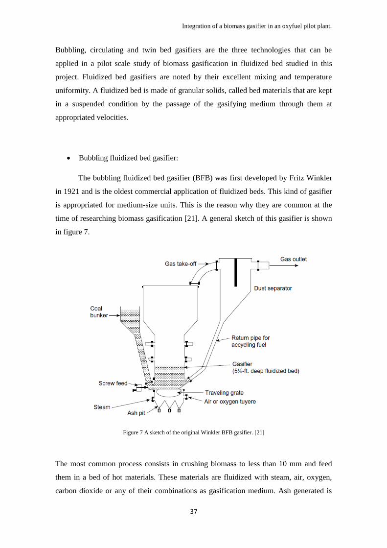
The bubbling fluidized bed gasifier (BFB) was first developed by Fritz Winkler
in 1921 and is the oldest commercial application of fluidized beds. This kind of gasifier
is appropriated for medium-size units. This is the reason why they are common at the
time of researching biomass gasification [21]. A general sketch of this gasifier is shown
in figure 7.
Figure 7 A sketch of the original Winkler BFB gasifier. [21]
The most common process consists in crushing biomass to less than 10 mm and feed
them in a bed of hot materials. These materials are fluidized with steam, air, oxygen,
carbon dioxide or any of their combinations as gasification medium. Ash generated is
Integration of a biomass gasifier in an oxyfuel pilot plant.
38
drained from the bottom of the bed and this one is usually kept in temperatures below
900ºC to avoid ash fusion and bed agglomeration. Fly ash and dragged bed material
escapes the bed through the gas outlet and depending on the use of the generated gas,
deposition of these particles can be carried out in a cyclone.
Commonly the gasifying medium is inserted in the bed through two different inlets, a
first-stage provides the adequate flow and velocity to maintain the bed fluidized, the
second-stage, usually added above the bed, converts un-reacted char particles and
hydrocarbons in useful gas.
Most fluidized bed gasifiers works with atmospheric pressure but in some cases High-
temperature Winkler (HTW) technology is used to provide high quality gas using
temperatures above 800ºC and pressures of 10 bars, but this technology is expensive,
risky and not really recommendable in case of designing a gasifier with the objective of
producing a gas that is later going to be combusted.
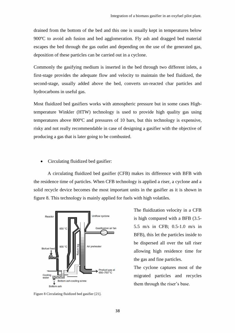
Circulating fluidized bed gasifier:
A circulating fluidized bed gasifier (CFB) makes its difference with BFB with
the residence time of particles. When CFB technology is applied a riser, a cyclone and a
solid recycle device becomes the most important units in the gasifier as it is shown in
figure 8. This technology is mainly applied for fuels with high volatiles.
Figure 8 Circulating fluidized bed gasifier [21].
The fluidization velocity in a CFB
is high compared with a BFB (3.5-
5.5 m/s in CFB; 0.5-1.0 m/s in
BFB), this let the particles inside to
be dispersed all over the tall riser
allowing high residence time for
the gas and fine particles.
The cyclone captures most of the
migrated particles and recycles
them through the riser’s base.
Integration of a biomass gasifier in an oxyfuel pilot plant.
39
One of the largest CFB gasifier created is placed in Lahti, Finland, plant where this
gasifier generates a gas from waste solids that is co-fired with coal.
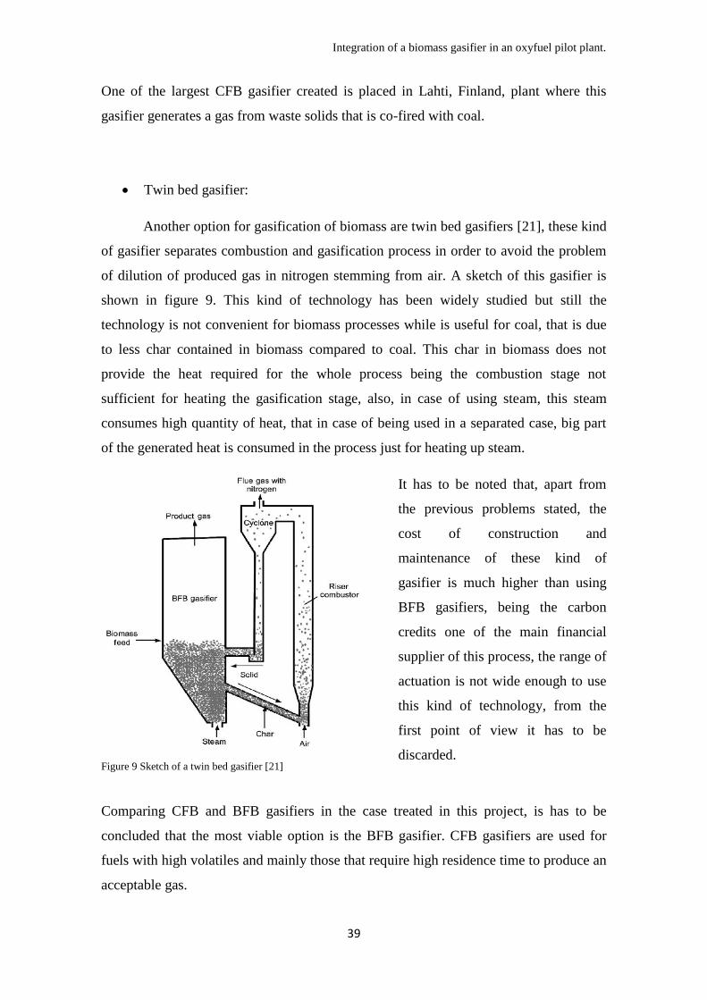
Twin bed gasifier:
Another option for gasification of biomass are twin bed gasifiers [21], these kind
of gasifier separates combustion and gasification process in order to avoid the problem
of dilution of produced gas in nitrogen stemming from air. A sketch of this gasifier is
shown in figure 9. This kind of technology has been widely studied but still the
technology is not convenient for biomass processes while is useful for coal, that is due
to less char contained in biomass compared to coal. This char in biomass does not
provide the heat required for the whole process being the combustion stage not
sufficient for heating the gasification stage, also, in case of using steam, this steam
consumes high quantity of heat, that in case of being used in a separated case, big part
of the generated heat is consumed in the process just for heating up steam.
Figure 9 Sketch of a twin bed gasifier [21]
It has to be noted that, apart from
the previous problems stated, the
cost of construction and
maintenance of these kind of
gasifier is much higher than using
BFB gasifiers, being the carbon
credits one of the main financial
supplier of this process, the range of
actuation is not wide enough to use
this kind of technology, from the
first point of view it has to be
discarded.
Comparing CFB and BFB gasifiers in the case treated in this project, is has to be
concluded that the most viable option is the BFB gasifier. CFB gasifiers are used for
fuels with high volatiles and mainly those that require high residence time to produce an
acceptable gas.

Integration of a biomass gasifier in an oxyfuel pilot plant.
40
Biomass used in this project is going to be the most simple and common one that can be
commercially found; woodchips. This biomass has been selected because the most
important topic in this project is to discover how to implement biomass gasification
technology in an oxyfuel plant, not the biomass sample itself. Woodchips is a really
clean kind of biomass with little ash and relatively high LHV causing really little
problems in the gasifier.
Woodchips do not require high residence time to produce a high enough LHV gas for
being combusted in the oxyfuel plant; this is the reason why a BFB gasifier has been
chosen for this analysis.
3.2 Bubbling fluidized bed gasifier: Mechanics and kinetics
With the information gathered at this point, the selection of a model for the BFB
gasifier chosen for this project must be made. It has to be noted that the constraints
surrounding the design of this unit are quite specific. This gasifier will use woodchips in
order to generate a product gas that is going to be combusted in an oxyfuel pilot plant,
in this pilot plant are available all gasifying agents used in gasification technology; air
from the environment, oxygen from the air separation unit (ASU) used in the oxyfuel
plant for burning the coal, steam from the steam power cycle and carbon dioxide from
the flue gas stream of the boiler.
Bioenergy group of the University of Seville has provided information about a gasifier
that fits the requirements of this study [22]. This gasifier erected in Cubilos del Sil
(Leon, Spain), is a 3 MWth BFB gasifier that uses oxygen and a flue gas stream
(consisting mainly in carbon dioxide and steam) from an oxyfuel plant placed in the
same site.
3.2.1 Mechanics:
The working process of this demonstration plant can be summarized by figure
10. This gasifier, taken as example, works with atmospheric pressure and a range of
temperatures of 800ºC-900ºC. The amount of biomass fed to the gasifier is 500kg/h
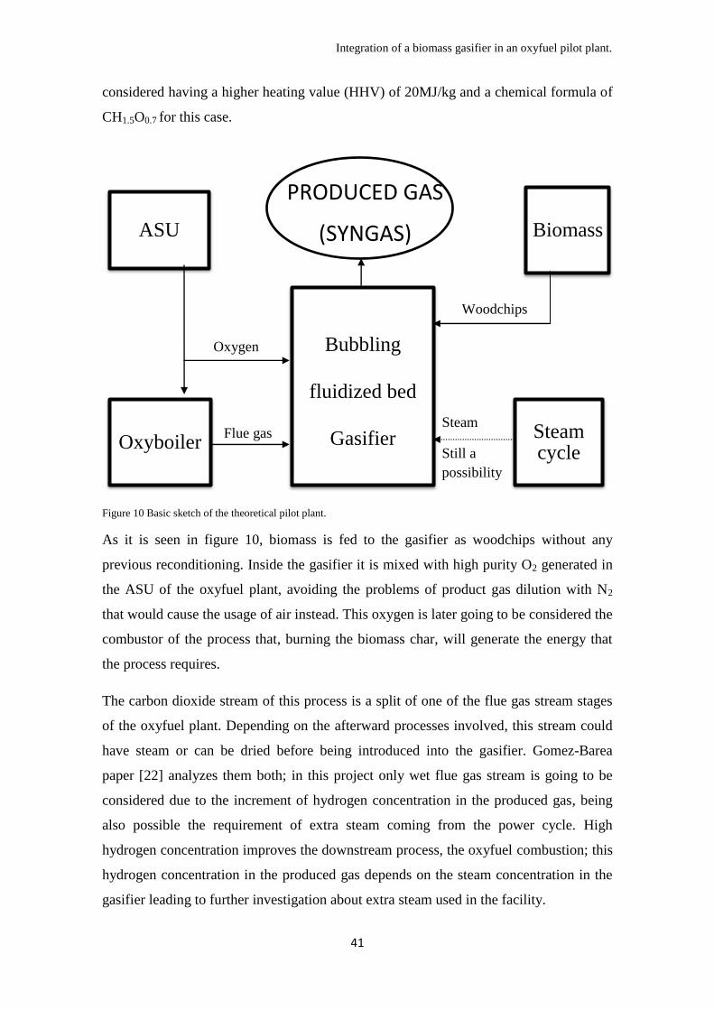
Integration of a biomass gasifier in an oxyfuel pilot plant.
41
considered having a higher heating value (HHV) of 20MJ/kg and a chemical formula of
CH1.5O0.7 for this case.
Figure 10 Basic sketch of the theoretical pilot plant.
As it is seen in figure 10, biomass is fed to the gasifier as woodchips without any
previous reconditioning. Inside the gasifier it is mixed with high purity O2 generated in
the ASU of the oxyfuel plant, avoiding the problems of product gas dilution with N2
that would cause the usage of air instead. This oxygen is later going to be considered the
combustor of the process that, burning the biomass char, will generate the energy that
the process requires.
The carbon dioxide stream of this process is a split of one of the flue gas stream stages
of the oxyfuel plant. Depending on the afterward processes involved, this stream could
have steam or can be dried before being introduced into the gasifier. Gomez-Barea
paper [22] analyzes them both; in this project only wet flue gas stream is going to be
considered due to the increment of hydrogen concentration in the produced gas, being
also possible the requirement of extra steam coming from the power cycle. High
hydrogen concentration improves the downstream process, the oxyfuel combustion; this
hydrogen concentration in the produced gas depends on the steam concentration in the
gasifier leading to further investigation about extra steam used in the facility.
Oxyboiler
Bubbling
fluidized bed
Gasifier Steam cycle
ASU Biomass
PRODUCED GAS
(SYNGAS)
Woodchips
Oxygen
Flue gas Steam
Still a
possibility

Integration of a biomass gasifier in an oxyfuel pilot plant.
42
3.2.2 Kinetics:
Gasification kinetics are complex, there exists many studies with many different
conclusions. In this stage of the project a qualitative analysis is going to be developed
and fundamentals are going to be shown with the aim of reaching a level of knowledge
that may create basis for further conclusions.
As it was defined as thermal conversion of organic material to combustible gases under
reducing conditions with a gasifying agent that can be air, oxygen, steam or carbon
dioxide [14], gasification kinetics can be summarized in figure 11.
Figure 41 Gasification process sketch [14]
It can be easily seen in figure 11 that gasification can be divided in the following
reaction and processes that will be produced in the gasifier at the same time:
Heating and drying: This is the first step of gasification, biomass contents a
variable concentration of water (in the example used this content is 6.28% p/p)
and it is desired to convert biomass into bone dry matter before next step is
achieved, this process requires temperatures from 100ºC to 200ºC generating
steam, that is also a reactant on several gasification reactions.
Pyrolysis: Pyrolysis is the rapid thermal decomposition of biomass in the
absence of oxygen. Some reactions in this process starts at 225ºC but pyrolysis
does not become rapid and complete until it reaches 400-500ºC. This process
generates volatiles including produced water, permanent gases, and tarry vapors,
forming pores in the remaining carbonaceous solid known as char. Permanent
gases include CO, CO2, H2 and light hydrocarbons, particularly methane. Tarry

Integration of a biomass gasifier in an oxyfuel pilot plant.
43
vapors are mainly anhydrosugars and other highly oxygenated compounds from
the decomposition of cellulose and hemicelluloses in biomass and phenolic
monomers and oligomenrs from the depolymerization of lignin. These last ones,
exposed to high temperatures can be cracked to smaller compounds or
condensed into larger ones that later would be major constituents of tar.
Combustion: during the whole process, oxygen present in the gas will react with
biomass volatiles in a combustion reaction. This reaction is exothermic and it
warms up and maintains the temperature of the process around 900ºC. The heat
provided by reaction of oxygen with biomass volatiles converts this gasification
in a directly heated process. Fed oxygen is the main control variable of the
temperature of the process, high temperatures would lead to undesired reactions
and damage to the facility generating a lower LHV gas, a lower temperature
would not generate the compounds desired due to the endothermic characteristic
of gasification reactions that later on will be explained in dept.
Gasification itself: after drying and pyrolysis the remaining product is also
called char, carbonized material coming from the previous biomass. This
gasification consists in several reactions between remaining char and CO2, steam
or oxygen.
Also, this stage is one of the most complicated to predict, later on some
information will be shown in order to facilitate the understanding of this phase.
The transport phenomena that can be found in gasification are important in case of
analyzing the controlling steps on this process. First of all gasifying agent must enter in
the pores (adsorption step) to react with that fixed carbon (reaction step) and the
products of that reaction must be released from inside the pores (desorption step), also
showed in figure 12. These three steps creates different resistances that components
must get over, so it would be interesting to create a model that helps to understand how
the composition on the bulk gas, the size and shape of particles and the composition
inside particles affect this process, all apart from the logic constraints as temperature or
pressure.

Integration of a biomass gasifier in an oxyfuel pilot plant.
44
Figure 5 Char gasification transport phenomena model for a
generic gasifier using air.
In this project the gasifier designed
by the bioenergy group of
Universidad de Sevilla [22], is a
bubbling fluidized bed that uses
steam, CO2 and oxygen as gasifying
agents.
In order to understand the
performing of this gasifier, first of
all, a reaction analysis must be done.
Considering that three different
gasifying agents are reacting with
biomass, an analysis of their reaction independently is going to be done, even with the
fact that all reactions are active during the process at the same time.
There exists a wide variety of mathematical models for biomass gasification; each one
with a really different point of view, P. Kausal [23] made a really interesting kinetic
model for biomass gasification that is usable for any ratio of gasifying agents. This
project is not going to focus on kinetic laws, only a overview is going to be done, and
the results are going to be assumed as those received by [22]. The gasifier studied
considers the reactions shown in table 3 in order to simplify the process.
Table 3: Reactions produced in the analyzed gasifier [22].
Oxygen.
Oxygen reaction with biomass is mainly going to generate heat, in order to do so
the reaction generated is combustion. This combustion could convert part of the
biomass in CO2 but in presence of low concentrations of oxygen this biomass could be
converted also in CO, but this project is an overview meaning that intermediate or less
common reactions will not be analyzed. This last reaction will not be considered and
only combustion to CO2 is going to be studied [22].
Integration of a biomass gasifier in an oxyfuel pilot plant.
45
The oxygen stream fed into the gasifier consists in high purity oxygen due that it was
separated from nitrogen in the oxyfuel plant ASU. This means, that reaction of nitrogen
and its presence effect is going to be ignored in this project.
Consequently, combustion with oxygen will generate heat, being the supposed gasifier a
direct heated process; this heat will feed the rest of the reactions involved in the process
maintaining it around 900ºC. Oxygen uses biomass volatiles to generate heat, as a fuel,
and the fuel used by oxygen will not be converted in product gas, reducing the LHV of
the produced gas. Oxygen analyzed in this project does not act as reducing agent in the
gasification process; it only acts as oxidant in the combustion reaction.
Combustion of volatiles is not the main task of the process; the less oxygen used in the
process maintaining the temperature at 900ºC the higher LHV of the gas due to the
generation of less CO2. This process is maintained at 900ºC, that means that a way to
heat up the process is required, direct or indirect heating. Indirect heating has to be
discarded in terms of generating heat outside the case of the gasifier, this requires heat
exchangers and involves a lesser thermodynamic efficiency. Other route of indirect
heating could be the maximization of the inlet temperature of the different streams,
causing a less requirement of oxygen in the gasifier, routes that will be analyzed in
chapter four.
Oxygen generated in the ASU has to be mixed with the other feeding streams except for
biomass feeding stream. This mixing will facilitate the design of the gasifier and carries
out no risk due to the non existence of combustible compounds in the steam stream or
the flue gas stream being the components of those streams CO2, N2, H2O and O2. This
mixture also prevents hot spots during the process ensuring a good dilution of O2 with
the reducing agents.
Steam and carbon dioxide.
Steam and carbon dioxide are considered as reducing agents in this process
being the generators of the reducing atmosphere. As it was mentioned by [22] carbon
dioxide generates CO, H2 and steam, while steam generates CO, H2 and CO2, meaning
that R2 to R5 are kinetically related. This generates complications at the time of predict
the behavior of this process while using different concentrations of both reducing
agents. Gomez-Barea et al. [22] obtained the results shown in table 4 at 900ºC with a
flue gas recycle stream temperature of 150ºC (Wet flue gas: CO2/H2O/O2/N2=67/25/3/5

Integration of a biomass gasifier in an oxyfuel pilot plant.
46
(in mass %)) and oxygen stream temperature of 50ºC using 500kg/h of woodchips
gasified in a 1 m diameter BFB gasifier.
WET FLUE GAS
λm
0.75
(Case A) 1.5
3
(Case B)
Oxygen stream
kgO2 stream/
kgdafb 0.33 0.34 0.36
Slipstream from oxyboiler
gas
Kg flue gas/ kg
dafb 0.4 0.8 1.6
Λo
kgO2/kg
stoichiometric O2 0.25 0.27 0.29
Λs
KgH2O/kg
stoichiometric
H2O 0.36 0.72 1.43
Λcd
kgCO2/kg
stoichiometric
CO2 0.4 0.79 1.57
Compostition (dry gas) % v/v
CO
40.2 34.7 26.3
H2
28.3 25.4 20.3
CO2
23.3 31.4 44.3
CH4
5.7 5.2 4.5
N2
2.2 3 4.3
Lower heating value (Dry
gas) MJ/Nm3
10.5 9.3 7.4
Cold efficiency dry gas 0.83 0.79 0.72
Carbon conversion
0.99 0.98 0.95
Char conversión
0.97 0.94 0.87
H2/CO mol/mol 0.7 0.73 0.77 Table 4 Results of the theoretical gasifier from Gomez-Barea [22]
Being λm=λs+λcd the total reducing agents introduced.
The higher reducing agents concentration introduced, being both proportionally
increased, the higher yield H2/CO concentration produced due to the higher speed of
reactions produced by steam. But this higher reducing agent concentration require
higher oxygen feeding due to the requirement of heating up the reducing agents and
produces a lower LHV gas due to the dilution of H2 and CO in inert gases generated in
the combustion.
Increasing λm (reducing agents rate) does not improve the process, but increases the
H2/CO yield. Being H2 generated mainly by steam, an extra steam supply system could

Integration of a biomass gasifier in an oxyfuel pilot plant.
47
be inserted, using the steam cycle of the oxyfuel process is an interesting option for this
porpoise.
Ahmed and Gupta [24] discovered in their experiments relevant issues about the effect
of using CO2 and steam for gasification of woodchip char (Figure 13 to 15). They
concluded that the reaction rate of the whole process is mainly governed by carbon
dioxide being the slower reaction of both gasifying agents.
They also concluded than for the three different particle resistances, only desorption
reaction and surface reaction can control the whole process being the desorption
reaction fast enough. This means that different partial pressures inside the gasifier does
not affect the effectiveness of the process corroborating the results of [22] that exposed
a decrement on efficiency with higher presence of reducing agents in the process.
This explains that a residence time for char inside the gasifier in a range of 20-60 min
will relate both reactions. It has to be noted that higher steam concentrations improves
the process but in order to use higher concentrations of steam, this steam need to be
generated producing a loss in global efficiency due that steam must be extracted from
the steam cycle. Flue gas stream from oxyfuel plant is going to be generated in any
case; this stream must be considered as free. That is the reason why only wet flue gas
stream possibilities are examined in this project due that in the document [22] another
flue gas stream extracted right after condensation in the oxyfuel process is analyzed.
Wet flue gas stream has steam and it does not affect the efficiency of the process, all the
way around, it improves it.
Many models from Wang and Kinoshita model [25] to Thilakavathi [26] could be used
for a better understanding of the behavior of the different components inside a bubbling
fluidized bed gasifier. Table 5 [27] shows a total of the possible reactions findable in a
gasification process, this is directly related with the difficulty of establishing a model
for this process. Gomez-Barea in the review [27] stated that devolatilization and
conversion of char and tar still requires further investigation because most of models are
still semi-empirical, even fluidization models for reactor design are mostly semi-
empirical.

Integration of a biomass gasifier in an oxyfuel pilot plant.
48
Table 5 Main reactions in biomass gasification [27]
Figure 13 Evolution of reaction rate at gasifying agent
partial pressure of 1.5 Bars.
Figure 14 Evolution of reaction rate at gasifying agent
partial pressure of 1.2 Bars.
Figure 15 Evolution of reaction rate at gasifying agent partial pressure of 0.9 Bars.
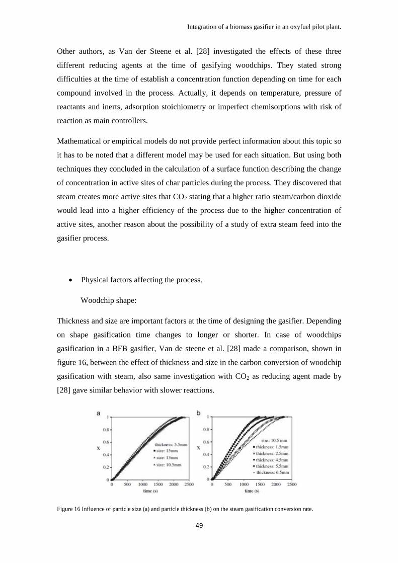
Integration of a biomass gasifier in an oxyfuel pilot plant.
49
Other authors, as Van der Steene et al. [28] investigated the effects of these three
different reducing agents at the time of gasifying woodchips. They stated strong
difficulties at the time of establish a concentration function depending on time for each
compound involved in the process. Actually, it depends on temperature, pressure of
reactants and inerts, adsorption stoichiometry or imperfect chemisorptions with risk of
reaction as main controllers.
Mathematical or empirical models do not provide perfect information about this topic so
it has to be noted that a different model may be used for each situation. But using both
techniques they concluded in the calculation of a surface function describing the change
of concentration in active sites of char particles during the process. They discovered that
steam creates more active sites that CO2 stating that a higher ratio steam/carbon dioxide
would lead into a higher efficiency of the process due to the higher concentration of
active sites, another reason about the possibility of a study of extra steam feed into the
gasifier process.
Physical factors affecting the process.
Woodchip shape:
Thickness and size are important factors at the time of designing the gasifier. Depending
on shape gasification time changes to longer or shorter. In case of woodchips
gasification in a BFB gasifier, Van de steene et al. [28] made a comparison, shown in
figure 16, between the effect of thickness and size in the carbon conversion of woodchip
gasification with steam, also same investigation with CO2 as reducing agent made by
[28] gave similar behavior with slower reactions.
Figure 16 Influence of particle size (a) and particle thickness (b) on the steam gasification conversion rate.

Integration of a biomass gasifier in an oxyfuel pilot plant.
50
It can be concluded that, in case of gasification of woodchips with steam, size of
particles does not affect the process. Thickness, in this case, affects effectiveness
increasing total conversion time up to twice the time for a six times thicker particle.
Being the process analyzed in this project gasification using steam and also CO2 as
reducing agents, it is possible that the conversion would be lower for same thickness as
the previous graphs. It has to be noted with this that possibly a pretreatment of the
woodchips could lead into a better efficiency in the process.
Temperature:
Temperature of the process affects directly the reactivity of the compounds related. A
higher temperature leads to a higher reactivity of each of the reducing agents with the
biomass. Considering residence times over 2000 s it has to be noted that conversion
generated by steam, being steam reactivity high, will have final values close to complete
conversion in temperatures up to 900ºC as experiments made by [27] proved using
woodchips gasified with steam and air. In case of using CO2, temperature required for a
considerable conversion will be higher but this temperature has to be limited due to the
melting points of some ash compounds that provoke slagging and fouling inside the
gasifier. This is the reason why the temperature inside the gasifier is set to 900ºC, this
leads into a lesser carbon conversion with lower ratio steam/CO2.
Temperature of the process is a function of the oxygen fed into the gasifier, this oxygen
will react with biomass in a combustion reaction generating heat. But this is not the only
factor affecting the process, inlet temperature of flue gas and oxygen and possible
preheat of biomass would affect the temperature of the gasifier, and it has to be noted
that a possible steam stream would affect the temperature of the process. A control
system is recommended in this case due to the many variables possibly uncontrolled in
the process as temperature of the flue gas or temperature of the steam.
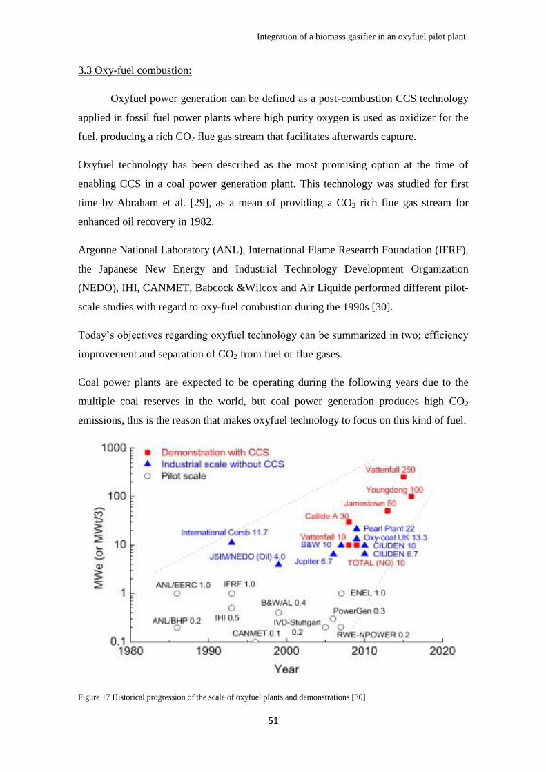
Integration of a biomass gasifier in an oxyfuel pilot plant.
51
3.3 Oxy-fuel combustion:
Oxyfuel power generation can be defined as a post-combustion CCS technology
applied in fossil fuel power plants where high purity oxygen is used as oxidizer for the
fuel, producing a rich CO2 flue gas stream that facilitates afterwards capture.
Oxyfuel technology has been described as the most promising option at the time of
enabling CCS in a coal power generation plant. This technology was studied for first
time by Abraham et al. [29], as a mean of providing a CO2 rich flue gas stream for
enhanced oil recovery in 1982.
Argonne National Laboratory (ANL), International Flame Research Foundation (IFRF),
the Japanese New Energy and Industrial Technology Development Organization
(NEDO), IHI, CANMET, Babcock &Wilcox and Air Liquide performed different pilot-
scale studies with regard to oxy-fuel combustion during the 1990s [30].
Today’s objectives regarding oxyfuel technology can be summarized in two; efficiency
improvement and separation of CO2 from fuel or flue gases.
Coal power plants are expected to be operating during the following years due to the
multiple coal reserves in the world, but coal power generation produces high CO2
emissions, this is the reason that makes oxyfuel technology to focus on this kind of fuel.
Figure 17 Historical progression of the scale of oxyfuel plants and demonstrations [30]
Integration of a biomass gasifier in an oxyfuel pilot plant.
52
But the implementation of this technology decreases the global efficiency of the process
in a range of 9-13%; the process is more expensive than air-blown power plants without
including the costs of CCS technology. Implementing co-firing of biomass produced
gas could lead to new revenues from carbon credits increasing the benefits of the power
plant up to the level of a coal power plant with no oxyfuel technology implemented.
This problem is the main cause of the non existence of full power plants with this
technology. There exist many pilot plants, demonstration plants and semi-commercial
plants, but this technology has not been applied to commercial purposes yet as it can be
seen in figure 17.
3.3.1 Oxyfuel mechanics:
Oxyfuel plant mechanics does not involve extremely complicated terms to be
understood. Figure 18 shows a basic sketch of the process. As it is seen in the figure 18,
fuel is fed in the boiler and combusted in a CO2 rich atmosphere. This atmosphere is
generated with the recycle of the flue gas stream situated right after the ash removal
stage, in order to avoid ash accumulation in the boiler. As it was explained, the
objective of this technology is to capture and storage the CO2 produced, that is the
reason why fuel is combusted with oxygen of high purity from the ASU unit. The flue
gas stream, being mainly composed by CO2 is cleaned and compressed at the end of the
process with the aim of a later storage of it.
It has to be noted that this technology is commonly compared with standard air firing
coal power plants. The differences are notables, nitrogen, main inert gas in standard coal
boilers, has different properties than CO2 at the time of act as a dissipater of heat inside
the furnace. CO2 gas is denser than N2 and the CO2–H2O mixture has a higher specific
heat capacity and different radiation and absorption characteristics. Therefore, the flue
gas recycle ratio and thereby the oxygen concentration during oxy-fuel combustion is
the main parameter that determines the optimum firing conditions.
The resulting adiabatic temperature in O2/Flue gas mixtures is much lower than the one
reached in air firing conditions at comparable O2 concentrations, recycle ratio is design
in the way that it provides a combustion and heat transfer characteristics similar to the
air firing mode, this leads to a higher recycle ratio if it is compared with air firing mode.

Integration of a biomass gasifier in an oxyfuel pilot plant.
53
Figure 18 Flow sheet of oxyfuel technology for power generation with CO2 capture and storage, showing the
additional unit in bold compared to air fuelled operation. [31]
In a more specific point of view there are a few characteristic points that create the
difference between air firing and oxyfuel mode in a coal power plant.
Pyrolysis and char combustion:
Devolatilisation and char combustion process is quite interesting at the time of
analyzing the oxyfuel process. It has been proven [32] that volatile release is higher in a
CO2-rich environment than in the case with N2. This is important in case of introducing
extra volatiles as H2, CO and tar using gasification co-firing. Also CO2 has a significant
effect in pyrolysis gas speciation. In figure 19, the effects of using each atmosphere are
shown, experiments carried out in a drop tube furnace with lignite.
Figure 19 Gas concentrations at the end of the reactor for Lausitz coal pyrolysis in 100% N2 and 100% CO2
environments [32].
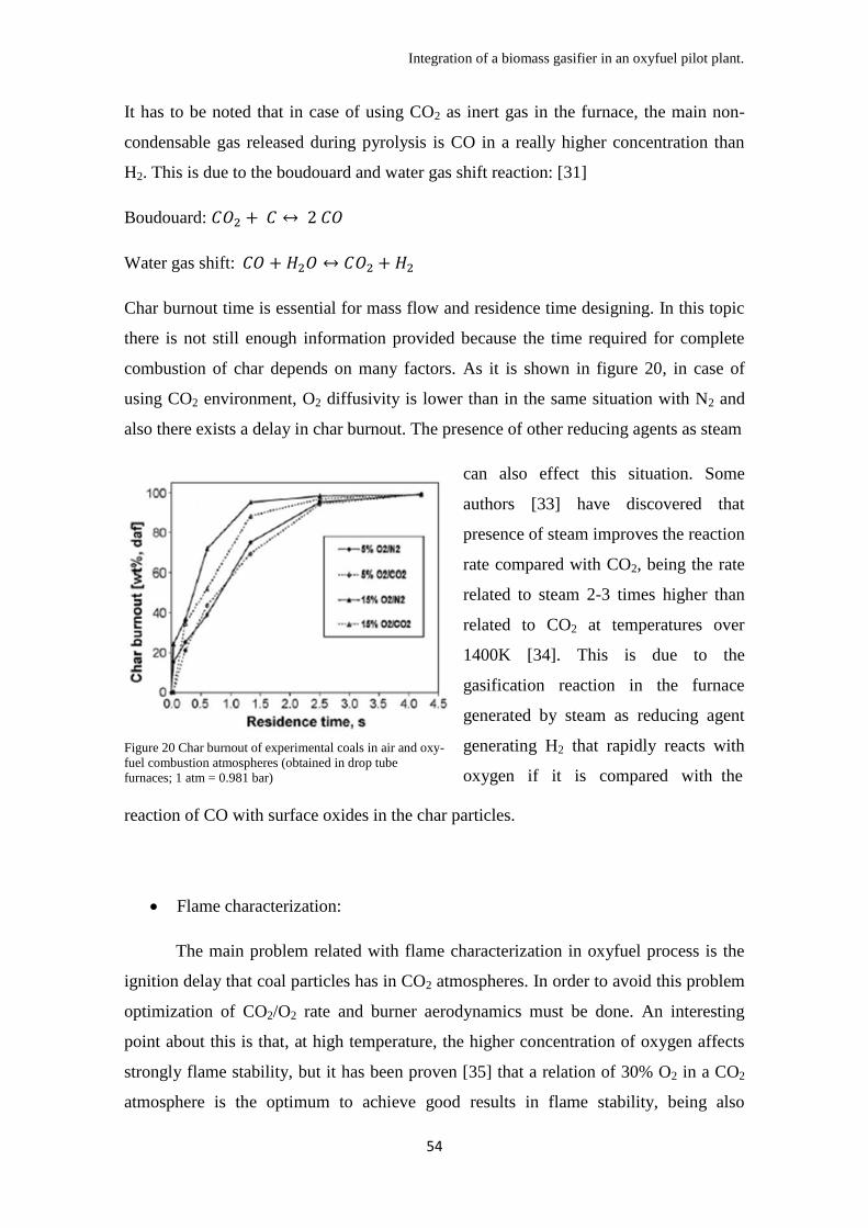
Integration of a biomass gasifier in an oxyfuel pilot plant.
54
It has to be noted that in case of using CO2 as inert gas in the furnace, the main non-
condensable gas released during pyrolysis is CO in a really higher concentration than
H2. This is due to the boudouard and water gas shift reaction: [31]
Boudouard:
Water gas shift:
Char burnout time is essential for mass flow and residence time designing. In this topic
there is not still enough information provided because the time required for complete
combustion of char depends on many factors. As it is shown in figure 20, in case of
using CO2 environment, O2 diffusivity is lower than in the same situation with N2 and
also there exists a delay in char burnout. The presence of other reducing agents as steam
Figure 20 Char burnout of experimental coals in air and oxy-
fuel combustion atmospheres (obtained in drop tube
furnaces; 1 atm = 0.981 bar)
can also effect this situation. Some
authors [33] have discovered that
presence of steam improves the reaction
rate compared with CO2, being the rate
related to steam 2-3 times higher than
related to CO2 at temperatures over
1400K [34]. This is due to the
gasification reaction in the furnace
generated by steam as reducing agent
generating H2 that rapidly reacts with
oxygen if it is compared with the
reaction of CO with surface oxides in the char particles.
Flame characterization:
The main problem related with flame characterization in oxyfuel process is the
ignition delay that coal particles has in CO2 atmospheres. In order to avoid this problem
optimization of CO2/O2 rate and burner aerodynamics must be done. An interesting
point about this is that, at high temperature, the higher concentration of oxygen affects
strongly flame stability, but it has been proven [35] that a relation of 30% O2 in a CO2
atmosphere is the optimum to achieve good results in flame stability, being also
Integration of a biomass gasifier in an oxyfuel pilot plant.
55
devolatilisation and particle ignition similar to the ones in air for temperatures above
1300ºC.
Choosing oxygen concentration is not an easy task, as it was explained before, the
higher concentration the higher conversion and efficiency of the process but lesser
flame stability that could cause problems.
In case of requiring different conditions, it can be stated that oxyfuel combustion needs
new designs on burners. University of Stuttgart [30] designed burners with O2 direct
injection that provided conversion and stability acceptable for a wide variety of coals
with high or low volatiles. This is interesting in case of using different fuels at a time in
case of mixing both fuels in the burner.
NOx and sulfur emissions:
NOx emissions are one of the main advantages at the time of using oxyfuel mode
in a coal power plant. Using oxygen and CO2 atmospheres generates less NO2 than air
firing mode [36]. The reason is simple, there is only a small concentration of N2 during
the process, even more, while recycling flue gas, NOx compounds are decomposed with
in-flame hydrocarbons and reducing atmosphere near the flame.
Nevertheless, HCN and NH3 concentrations are higher in the exhaust gas of an oxyfuel
process compared to air processes, coming from those NOx that are being decomposed
in the flame, but not in high concentrations. These gases can provoke corrosion
problems inside the boiler.
In general terms, NOx formation is reduced in a 60 -80 % compared with air combustion
but with the drawback of generating little corrosion problems.
The case of SO2 is similar, using oxyfuel combustion reduces SO2 emissions compared
to air combustion, in an order of 2/3 [30]. This reduction appears due to the retention of
sulfur in the ash via sulphation and the high concentration of SO2 inside the furnace due
to the flue gas recycle.
As it happens with NOx compounds there exists other compounds generated in the
oxyfuel process, it is SO3. The concentration of SO3 can be up to three and a half times

Integration of a biomass gasifier in an oxyfuel pilot plant.
56
higher using oxyfuel than using air. So that, sulfur concentration in ash is higher
because all sulfur introduced comes from the coal used.
It has to be noted that, even when emissions of SOx is not as high as in the air case,
there exists high concentration of it inside the boiler. This leads to corrosion problems
in the boiler involving a careful material selection, operation of the boiler at higher
temperature and removal of steam and part of the SO2 present in the flue gas recycle.
Slagging and fouling:
Slagging is the formation of molten or partially fused deposits on furnace walls
or convection surfaces exposed to radiant heat. Fouling is defined as the formation of
deposit on convection heat surfaces such as superheater and reheaters. Those both are
the most important problems at the time of talking about ash deposition in coal power
plants.
Ash deposition is an important issue to examine when analyzing any kind of coal power
generation process, even when this topic has not been analyzed widely in oxyfuel
studies. The main variables that affect it are particle trajectory and ash viscosity, these
variables depend also on the aerodynamics at the burner exit and inside the boiler; and
the size, composition and temperature of the burning coal particles and also the gas
composition. SO2 being much more concentrated in oxyfuel processes affects
considerably ash slagging and fouling but the lesser flame temperature reduces slagging
propensity. Elevated levels of alkali metals cause accumulation of sintered ash in the
convection pass of the boiler, also known as fouling.
Slagging and fouling are the cause of the implementation of cleaning systems in the
recycle stream to avoid ash accumulation that leads on propensity of causing these
problems.
Corrosion:
Oxyfuel processes produce high concentration of corrosive gases (SO2, H2S,
HCl) that produce considerable problems of corrosion of water-wall and super-heater
Integration of a biomass gasifier in an oxyfuel pilot plant.
57
tubes. CO2 concentration also collaborates in this corrosion due to the carbon
enrichment of the metal surfaces causing locally incomplete oxide scale.
Most steels alloys use chromium to defend the metal surface against corrosion and
oxidation, in case of using CO2, many authors [37] have discovered permeability of
these alloys to CO2 molecules, generating carburization of the surface.
Some investigations about corrosion problems have been analyzed by Vattenfall in
Schwarze Pumpe Pilot plant [46] but these effects are still on investigation and it is not
possible to state any relevant information about this topic.
Having a general idea of how oxyfuel process works it is necessary to use a reference
for this investigation, that model will be the Vattenfall Schwarze Pumpe pilot plant in
Germany. This pilot plant is the most appropriate plant to analyze the integration of a
gasification process on it, because of the variety of information provided by the
company. The size of the plant is also interesting because of the other reference used in
this project, the gasifier designed by Gomez-Barea et al. [22]. This pilot plant is a 30
MWth oxyfuel plant where an integration of a gasifier of 3 MWth is enough to achieve
interesting results.
3.4 Vattenfall Schwarze Pumpe plant
As example the Vattenfall’s 30 MWth Oxyfuel Pilot Plant in Schwarze Pumpe is
going to be analyzed. The oxyfuel pilot plant was built in 2008 next to the lignite fired
power station built south to Berlin; it consists of a single top-mounted, pulverized fuel
burner and the subsequent flue gas cleaning equipment; electrostatic precipitator, wet
flue gas desulphurization and the flue gas condenser. In addition to these components, a
CO2 separation plant is placed downstream of the flue gas condenser to produce liquid
CO2. A cryogenic air separation unit located at the site will supply gaseous oxygen with
a minimum purity of 99.5% required for the combustion. The burner is designed for
both pre-dried lignite and bituminous coal for future testing.

Integration of a biomass gasifier in an oxyfuel pilot plant.
58
Figure 21 Basic sketch of the Schwarze Pumpe pilot plant [39].
This pilot plant had an investment of 60 million € and a research budget of 40 million €.
First results indicate that 95% of the produced CO2 is captured with a 98% of purity.
Compared with a standard coal boiler, at equivalent installed power in both plants the
total loss of efficiency implementing oxyfuel technology is around 9%, not high if
governmental incentives are achieved.
Being a not so developed technology, this kind of plants are subjected to new
investigations making possible an improvement in efficiency and also reaching 100%
carbon capture. Vattenfall has settled as objective a cost of 20€ per ton of CO2 avoided
in 2030, considering that before nowadays economical crisis 20€ per ton of CO2 was the
EUA price, it is not negligible the potential benefit that this technology carries. This
oxyfuel technology is applicable to air fuelled coal boilers already constructed, creating
a double interest in this pilot plant, retrofit and new development. [39]
This pilot plant uses the same lignite as the industrial plant already working in the same
place, this fine lignite powder is fed to the boiler with a maximum feeding of 6 t/h.
Being this pilot plant not big enough to create by itself power with enough efficiency,
the produced steam is utilized in an auxiliary turbine in the industrial plant with 6-8
MWel at full load. [40]
Comparing the results achieved by Vattenfall [41], it is proven that the most promising
option is oxyfuel mode compared to pre-combustion or post combustion due to higher
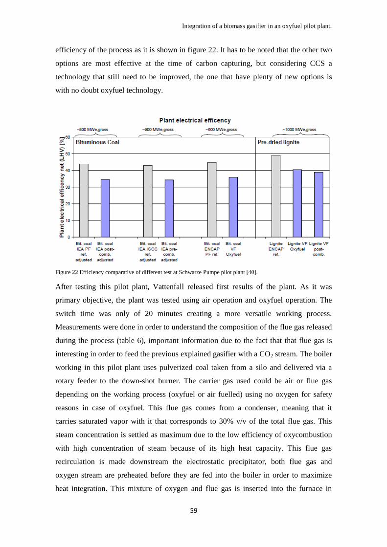
Integration of a biomass gasifier in an oxyfuel pilot plant.
59
efficiency of the process as it is shown in figure 22. It has to be noted that the other two
options are most effective at the time of carbon capturing, but considering CCS a
technology that still need to be improved, the one that have plenty of new options is
with no doubt oxyfuel technology.
Figure 22 Efficiency comparative of different test at Schwarze Pumpe pilot plant [40].
After testing this pilot plant, Vattenfall released first results of the plant. As it was
primary objective, the plant was tested using air operation and oxyfuel operation. The
switch time was only of 20 minutes creating a more versatile working process.
Measurements were done in order to understand the composition of the flue gas released
during the process (table 6), important information due to the fact that that flue gas is
interesting in order to feed the previous explained gasifier with a CO2 stream. The boiler
working in this pilot plant uses pulverized coal taken from a silo and delivered via a
rotary feeder to the down-shot burner. The carrier gas used could be air or flue gas
depending on the working process (oxyfuel or air fuelled) using no oxygen for safety
reasons in case of oxyfuel. This flue gas comes from a condenser, meaning that it
carries saturated vapor with it that corresponds to 30% v/v of the total flue gas. This
steam concentration is settled as maximum due to the low efficiency of oxycombustion
with high concentration of steam because of its high heat capacity. This flue gas
recirculation is made downstream the electrostatic precipitator, both flue gas and
oxygen stream are preheated before they are fed into the boiler in order to maximize
heat integration. This mixture of oxygen and flue gas is inserted into the furnace in
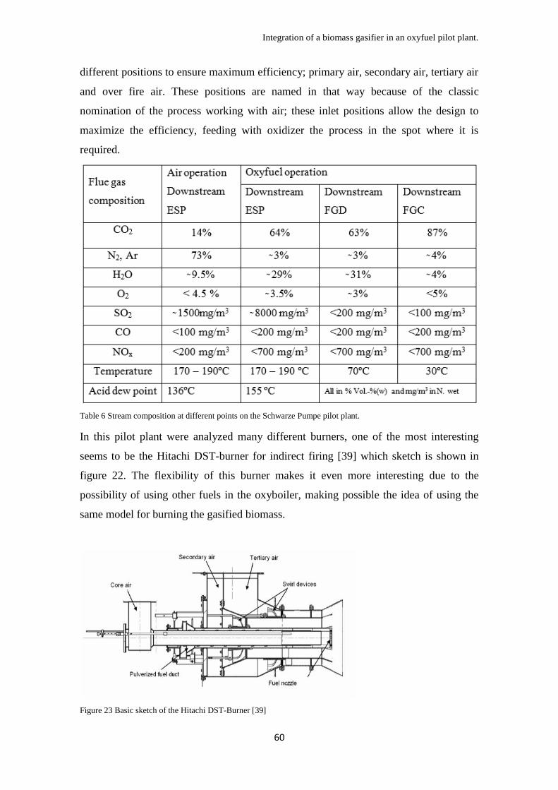
Integration of a biomass gasifier in an oxyfuel pilot plant.
60
different positions to ensure maximum efficiency; primary air, secondary air, tertiary air
and over fire air. These positions are named in that way because of the classic
nomination of the process working with air; these inlet positions allow the design to
maximize the efficiency, feeding with oxidizer the process in the spot where it is
required.
Table 6 Stream composition at different points on the Schwarze Pumpe pilot plant.
In this pilot plant were analyzed many different burners, one of the most interesting
seems to be the Hitachi DST-burner for indirect firing [39] which sketch is shown in
figure 22. The flexibility of this burner makes it even more interesting due to the
possibility of using other fuels in the oxyboiler, making possible the idea of using the
same model for burning the gasified biomass.
Figure 23 Basic sketch of the Hitachi DST-Burner [39]

Integration of a biomass gasifier in an oxyfuel pilot plant.
61
Investigations have discovered that high concentrations of oxygen are dangerous so the
concentration limit of oxygen has been set on 36% v/v in order to preserve flame
control. The lower concentration of oxygen has led into a higher concentration of CO in
the flue gas, something that is an important problem if CCS is planned to be carried out.
The upper emission limit for CO is 0.2kg/MWth, meaning that the minimum oxygen
concentration between the feeding streams has to be set in 23% v/v. In case of
integrating a gasification process in this plant many of these variables would change and
in every case a modification of the working process might be applied.
This furnace is considered as the first draft of the process, the second and third draft are
the heat exchanging surfaces containing two superheaters and five economizers. There
exists a fourth draft in the process that is also being called the De-NOx process that has
not been implemented yet. These different stages are shown in figure 21.
Right after the De-NOx process, a three field electrostatic precipitator removes fly ash
from the gas (“filter” in figure 20). Just after this process the recirculation is done,
reheating the flue gas up to 250ºC. This flue gas as it was explained is mixed with
99.5% pure oxygen from a standard cryogenic air separation unit with a two-stage
separation process is used in the pilot plant. This ASU is a generic unit GOX6600. Flue
gas desulphurization (FGD) is done just after the main flue gas splitting (secondary
recycle), by a wet-scrubber using limestone as a sorbent. This FGD cannot work under
air firing conditions.
Finally, condensation process is made with a two stage flue gas condenser; this
condensation cools down gases down to 30ºC before CO2 compression and also
eliminate water soluble acidic compounds. Just after this a primary recycle is done used
as transport gas for the coal feeder.
CO2 compression is designed to create truck transportable CO2 with 99% of purity. The
main steps in the liquefaction process are:
Removal of any remaining water droplets.
Compression of the raw gas to about 1.25 Bar.
Adsorption of heavy metals, SOx, HCl and HF in an activated carbon bed.
Compression of raw gas in two stages with intercooling to about 22 bar.
Removal of remaining water in a bed with molecular sieves.

Integration of a biomass gasifier in an oxyfuel pilot plant.
62
Liquefaction of the CO2 and separation of the remaining gaseous phase
containing mainly N2, O2 and Ar together with gaseous CO2 in a stripper.
An external ammonia cooling system provides the required cooling. The liquefied CO2
is stored on-site in two 180 m3 tanks with the corresponding loading stations for trucks.
[42]

Integration of a biomass gasifier in an oxyfuel pilot plant.
63
CHAPTER 4: Integration of a biomass gasification process in an oxyfuel pilot plant.
As it has been explained before in chapter two and three of this project,
gasification of woodchips using a flue gas stream from an oxyfuel process, process
defined by Gomez-Barea [22], is analyzed in order to co-fire the generated product gas
in the already explained oxyfuel process in Schwarze Pumpe, the main objective of the
whole system is to create a carbon negative process that generates power and is
economically viable.
This process has not ever been designed, also both technologies involved, gasification
using CO2, O2 and steam mixtures and oxyfuel combustion of lignite coal, have not
been used industrially.
Many variables are going to be analyzed in this point in order to understand the
feasibility of this process and the areas of investigation that this technology has a lack
knowledge and need to be improved.
Different situations are going to be analyzed and results provided will be considered as
indications. Calculations made in here are handwritten calculations, many constraints
are not going to be considered, and these calculations have the objective of indicate
probable results.
A hypothetical environment is going to be created in the following lines, this situation
will be the insertion of the gasifying process from Bioenergy group of Universidad de
Sevilla [22] into the Vattenfall Schwarze Pumpe oxyfuel pilot plant mentioned before.
This will help into the discovering of the remaining questions still to be analyzed in this
area of investigation.
4.1 General aspects of the integration
This project analyzes basically the partial replacement of coal in an
oxycombustor by another fuel, in this case the produced gas in a biomass gasification
process. The gasification process, as it was explained, is a 3 MWth gasifier, the oxyfuel
process analyzed is a 30 MWth process. The general idea is to replace 3 MWth of the
oxyfuel process by the 3 MWth gasification process.

Integration of a biomass gasifier in an oxyfuel pilot plant.
64
The main objective is not to affect the efficiency of the process, generating a final
scheme where the whole produced power remains equal. Considering this, the total
replaced power in the oxyfuel is 3MWth, the 10% of the total output.
Characteristics of Schwarze Pumpe pilot plant are shown in table 7.
It is going to be considered that the oxyfuel process will generate same amount of steam
with same temperature and pressure in order not to vary the power capacity of the plant.
That means that the total potential heat inserted must equal to the heat produced by the
replaced coal.
In a general environment, the oxyfuel process will use the gas generated in the gasifier
to replace coal. This replacement must be done in energetic terms, providing the oxyfuel
process with enough energy to maintain the amount of steam produced.
Boiler:
Pulverised coal combustión
Thermal output 30 MWth
Steam production 40 t/h
Steam parameter 25 bar / 350ºC
Coal:
Pulverised lignite
(Lusatia región)
LHV 21000 kj/kg
Moisture 10.5 %
Coal required 5 t/h
Media:
Oxygen (purity 95 % –
99.5 %) 10 t/h
Auxiliary use 6.5 MWth
CO2 (liquid) 11 t/h
Table 7 General characteristics of Schwarze Pumpe pilot plant [43].
The gasifier process used [22] is going to be analyzed in this project focusing in the
results using a wet flue gas from the oxyboiler because of the better LHV and carbon
conversion that the presence of steam in the gasification process generates. Case A and
Case B from table 4 in chapter 3 are going to be analyzed in the following lines
providing two opposite cases, case A with lesser flue gas feeding and case B with
higher flue gas feeding. Depending on the LHV of the gas produced in the gasifier, a
different amount of coal would be replaced. Due to the low LHV provided by this
produced gas, the quantity of coal replaced cannot reach the expected 10% of the total
coal inserted but the value found of 6.95% for case A and 6.12% for case B is still
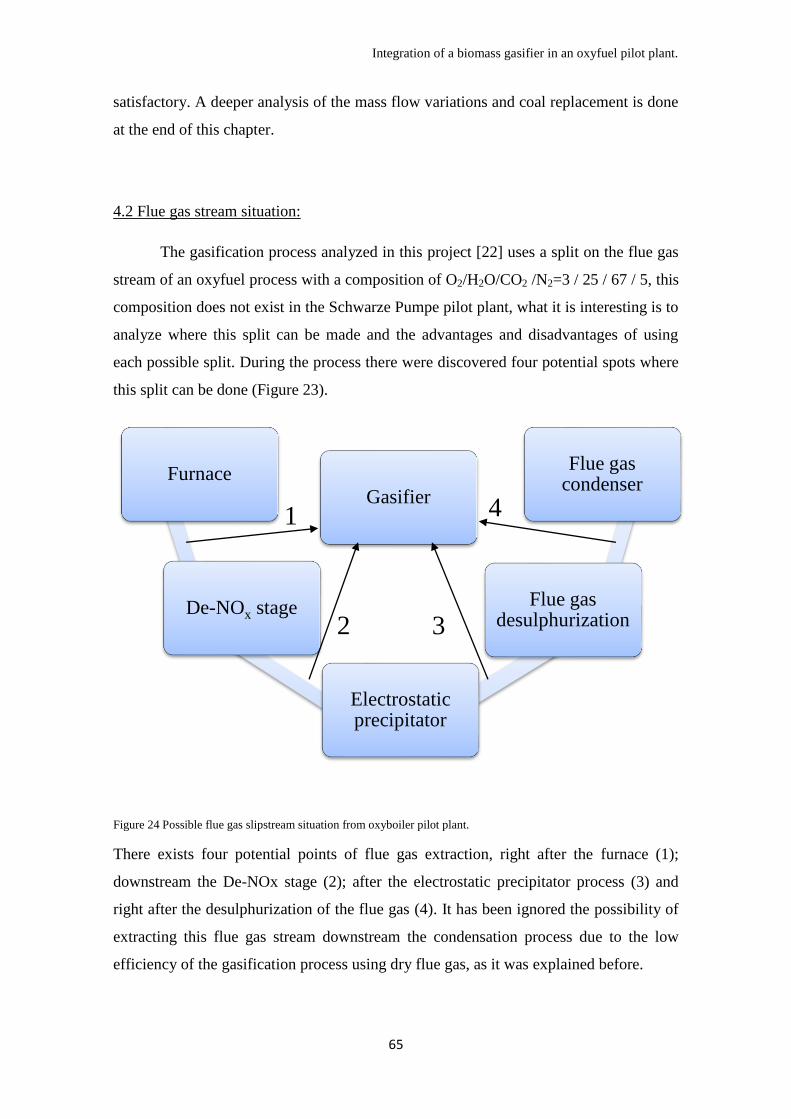
Integration of a biomass gasifier in an oxyfuel pilot plant.
65
satisfactory. A deeper analysis of the mass flow variations and coal replacement is done
at the end of this chapter.
4.2 Flue gas stream situation:
The gasification process analyzed in this project [22] uses a split on the flue gas
stream of an oxyfuel process with a composition of O2/H2O/CO2 /N2=3 / 25 / 67 / 5, this
composition does not exist in the Schwarze Pumpe pilot plant, what it is interesting is to
analyze where this split can be made and the advantages and disadvantages of using
each possible split. During the process there were discovered four potential spots where
this split can be done (Figure 23).
Figure 24 Possible flue gas slipstream situation from oxyboiler pilot plant.
There exists four potential points of flue gas extraction, right after the furnace (1);
downstream the De-NOx stage (2); after the electrostatic precipitator process (3) and
right after the desulphurization of the flue gas (4). It has been ignored the possibility of
extracting this flue gas stream downstream the condensation process due to the low
efficiency of the gasification process using dry flue gas, as it was explained before.
Furnace
De-NOx stage
Electrostatic precipitator
Flue gas desulphurization
Flue gas condenser
Gasifier 1
2 3
4

Integration of a biomass gasifier in an oxyfuel pilot plant.
66
Those three points have similar composition in terms of oxygen, steam, carbon dioxide
and nitrogen, being around 3 / 30 / 64 / 3 respectively[41], not far away from 3 / 25 / 67
/ 5 assumed in the analyzed gasifier (O2/H2O/CO2 /N2).
Even so, the integration of the product gas stream must be analyzed, depending on the
requirements of the oxyfuel process, a different cleaning system must be integrated
between the gasifier and the oxyboiler.
The key at this point is to understand the effect of NOx compounds, particles and
sulphur compounds inside the gasifier, depending on the effect the final design could
change.
Nitrogen compounds in the process:
Nitrogen derived compounds in a gasification process is an area not extensively
investigated. The most interesting document about this topic was made by Zhou et Al.
in 2000 [44]. Considering the information provided by Bioenergy Group of
Univerisidad de Sevilla, the woodchips samples used in the gasifier provided contained
a total of 2.16% of nitrogen in ultimate analysis.
This nitrogen, during gasification is converted in NH3, HCN, NO, char-N, tar-N, and N2
[45]. There is no information about releasing these compounds gasifying woodchips
with O2, CO2 and steam. But some authors have described briefly the behavior of these
compounds in O2/steam gasification as [45].
It is known that during gasification at temperatures over 700ºC, N2 is the main nitrogen
derived compound formed in the process, followed by NH3. NH3 is mainly formed by
the N-volatiles released during pyrolysis stage. Some percent is released by tar (0.37-
1.3%) and char (0.7-9.4%) being quite complex to predict its behavior [44].
It has also being proven that steam collaborates in the NH3 production, generating
hydrogen radicals that can react with char forming that compound. Also nitrogen
collaborates on this, making N-volatile to form more NH3 with the higher presence of
N2 [44].
NOx formation depends highly in the presence of oxygen. The case studied here has a
considerable presence of O2 but being only the oxidizer of the process, not a reducing
agent, this compound exists in quite a lower concentration compared to other
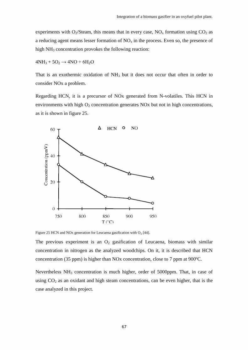
Integration of a biomass gasifier in an oxyfuel pilot plant.
67
experiments with O2/Steam, this means that in every case, NOx formation using CO2 as
a reducing agent means lesser formation of NOx in the process. Even so, the presence of
high NH3 concentration provokes the following reaction:
4NH3 + 5O2 → 4NO + 6H2O
That is an exothermic oxidation of NH3 but it does not occur that often in order to
consider NOx a problem.
Regarding HCN, it is a precursor of NOx generated from N-volatiles. This HCN in
environments with high O2 concentration generates NOx but not in high concentrations,
as it is shown in figure 25.
Figure 25 HCN and NOx generation for Leucaena gasification with O2 [44].
The previous experiment is an O2 gasification of Leucaena, biomass with similar
concentration in nitrogen as the analyzed woodchips. On it, it is described that HCN
concentration (35 ppm) is higher than NOx concentration, close to 7 ppm at 900ºC.
Nevertheless NH3 concentration is much higher, order of 5000ppm. That, in case of
using CO2 as an oxidant and high steam concentrations, can be even higher, that is the
case analyzed in this project.
Integration of a biomass gasifier in an oxyfuel pilot plant.
68
NOx, HCN and other nitrogen compounds with the exception of NH3 could be ignored
in the integration analysis. After the combustion stage at the oxyfuel process, NOx reach
concentrations of 600 ppm, much higher than the 7 ppm produced by the gasifier.
Considering that there is not any DeNOx still installed in the Schwarze Pumpe process,
it has to be considered that the difference between extraction before or after De-NOx
stage does not exist.
The case of NH3 insertion in the process could cause problems, 5000 ppm in the
produced gas means a concentration inside the burner of 350 ppm, this NH3 will be
converted in NOx, being the concentration 600 ppm as minimum, same value as it was
before integrating the process.
In general terms the insertion of the produced gas in the oxyboiler does not affect
extensively the process in terms of NOx, considering that NOx and HCN concentrations
are low, only NH3 can create a problem in the furnace but this NH3 is being oxidized
into NOx the concentration in the flue gas stream of the oxyboiler does not change
using biomass, still a De-NOx unit is required and Vattenfall is studying this topic at
this moment, in a near future this enterprise will release information about the topic.
Still the effect of the insertion in the gasifier of a concentration of 600 ppm of NOx in
the gasification process is not analyzed. Due to the reaction mentioned above, NOx
could engage the formation of NH3 but the concentration in the oxyboiler would remain
as the same.
Particles in the process:
In order to situate the slipstream of the flue gas that will feed the gasifier, the
effect of the electrostatic separator on the flue gas composition must be analyzed (points
2 or 3 in figure 24). This dust separator exists for two reasons; avoiding problems at the
carbon dioxide compression and purification unit and also, limiting the dust
accumulation in the furnace due to the flue gas recirculation. [46]
The efficiency of this precipitator has been proven to excess the 99.9%, flue gas with
dust has a concentration of this one around 6,8g/Nm3 (size 0.015-10 μm) with the

Integration of a biomass gasifier in an oxyfuel pilot plant.
69
composition shown in table 8. After the electrostatic precipitator (ESP) the
concentration of dust does not exceed 5mg/Nm3.
This limits the possibilities of extracting the flue gas directly after the boiler in order to
feed the gasifier. Introducing this dusty gas into the gasifier can cause problems that
will be analyzed later on and there is also a limit for dust concentration entering the
oxyfuel boiler.
Total moisture 9.5 %
Sulphur 0.82 %
Ash 5.7 %
SiO2 in coal ash 16 %
Al2O3 in coal ash 4.1 %
Fe2O3 in coal ash 20 %
CaO in coal ash 17 %
MgO in coal ash 9 %
SO3 in coal ash 22 %
Table 8 Composition (p/p) of Schwarze Pumpe precipitator
ash [46].
There is little information about fly ash
deposition generating fouling and slagging
in an oxyfuel process. This problem is
mainly caused by the melting point of the
fly ash, and this melting point is
characterized by the composition of this
ashes. It also depends on the movement of
fly ash inside the boiler, impacts in the
walls make particles to stack in sticky
wall provoking slagging problems. The
high sulfur content of these ashes collaborates on corrosion inside the furnace.
After the investigation in Schwarze Pumpe [46], they discovered many problems of
corrosion due to slagging and fouling in the walls of the furnace and the heat
exchangers, it may be recommended that the concentration of ash inserted in the boiler
does not exceed 5mg/Nm3.
Considering this information and also having in knowledge that there is no temperature
difference between positioning slipstream before or after the electrostatic precipitator
(point 2 and point 3 in figure 24), in order to split flue gas for feeding the gasifier with a
slipstream of the flue gas it may be concluded that there is no reason for using flue gas
slipstream before electrostatic precipitator.
This conclusion comes from the slagging and fouling problems, those problems are
going to appear also in the gasification process if dusty gas is used for feeding
gasification, no advantage have been found on using gas from point 2 that is the reason
of why it is being discarded.

Integration of a biomass gasifier in an oxyfuel pilot plant.
70
Regarding the gasifier, there is also generation of fly ash during the process. This fly
ash is going to be inserted in the oxyboiler, in case of not using any gas cleaning
system.
The total ash in the woodchips samples taken as example in this project is 0.67% (wet
basis). From this amount of ash, some part is going to be deposited in the gasification
process and extracted from the bottom part of the process (bottom ashes), but another
part, light enough to be carried by the gas extracted at the top of the process, is going to
be extracted with the product gas, it is called the fly ash.
Investigation made by Eberhadrt et Al. and other authors [47][48][49], discovered that
most of ashes produced are fly ash, considering the 0,7% of the total material inserted in
the gasifier to be fly ash with the composition close to the one shown in table 9.
Detection limit
(mg/kg)
Conc. Mass (g/kg) Error (g/kg)
Mg 217 7.07 0.17
Al 124 5.20 0.10
Si 56.5 16.8 0.17
P 63.2 1.76 0.05
S 41.9 1.76 0.04
K 56.3 10.1 0.10
Ca 105 50.8 0.51
Fe 65.8 9.92 0.10
Table 9 Composition of fly ash in a gasifier using oxygen.
The previous composition will be far away from the composition of fly ash generated in
the gasifier studied here but the most concentrated elements Ca, Si and K for woodchips
would remain as the most concentrated components. This area have not been widely
investigated, the effect of these ashes inside de oxyfuel process must be investigated.
Still this composition depends highly in the kind of biomass used, the safest option is to
analyze directly the amount of fly ash that this gasifier is going to introduce into the
furnace. Considering two cases in the Bioenergy Group study; case A with small flow
of reducing agents (lesser flue gas) producing 814.9 Nm3/h of gas, and case B with high
flow of reducing agents producing 1183.61 Nm3/h of gas. Considering the total ash
introduced the 0.7% w/w of the 500 kg/h of woodchips inserted the total of ash

Integration of a biomass gasifier in an oxyfuel pilot plant.
71
produced would be 3.5 kg/h. In case of using case A, the concentration of ash in the gas
produced would be 51.6 mg/Nm3, in case of using case B, the concentration drops to
50.9 mg/Nm3.
A cleaning system is required in case of introducing this gas into the furnace. Later on
will be explained the high advantages that a temperature around 900ºC in the gasifier
outlet carries out, that is the reason why a hot gas cleaning is required.
In order to analyze more in deep this topic it has to be considered that not only fly ash is
going to appear in this outlet, also the gasifier bed particles are conveyed upwards and
appear in the outlet. These particles are much larger than char particles and any
mechanical hot gas cleaning as a cyclone would have a high efficiency with them.
In case of using a cyclone, efficiency from 80 to 95 % can be expected. Using a cyclone
will reduce particle concentration to 3.5 ppm (mg/Nm3) for both cases A and B.
Considering the requirement of the oxyboiler of having a concentration of 5 mg/Nm3;
there exists no problem with these particles after the integration.
In case of using other kind of biomasses different to woodchips with higher ash
concentration, a hot cleaning system could be required, cold cleaning system will
decrease the temperature of the stream affecting deeply the flame stability and
condensing tar, being this last immediately discarded.
Using wet cleaning systems will cause a mixture between some tar compounds and
condensed water; this water would require really complicated water treatment.
Cold gas cleaning and wet gas cleaning are going to be discarded because of this.
It can be assumed that, right after a cyclone, another cleaning system could be applied
and this one must be a dry hot process in case of being required. Depending on the
requirements, [50] made an investigation about the different options available at the
time of cleaning this syngas. Solid contaminants removal by ceramic candle filters or
metallic filters, fluid contaminants removal by sorbents and trace removal by a
safeguard filter/catalyst, or a sorption bed.
This process required a solid removal with efficiency close to 99% treating a gas with
temperatures around 900ºC. A deep analysis on the advantages and drawbacks on using
ceramic candle filters was done in [51], whose investigations resulted on concentrations
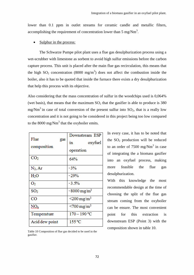
Integration of a biomass gasifier in an oxyfuel pilot plant.
72
lower than 0.1 ppm in outlet streams for ceramic candle and metallic filters,
accomplishing the requirement of concentration lower than 5 mg/Nm3.
Sulphur in the process:
The Schwarze Pumpe pilot plant uses a flue gas desulphurization process using a
wet-scrubber with limestone as sorbent to avoid high sulfur emissions before the carbon
capture process. This unit is placed after the main flue gas recirculation, this means that
the high SO2 concentration (8000 mg/m3) does not affect the combustion inside the
boiler, also it has to be quoted that inside the furnace there exists a dry desulphurization
that help this process with its objective.
Also considering that the mass concentration of sulfur in the woodchips used is 0,064%
(wet basis), that means that the maximum SO2 that the gasifier is able to produce is 380
mg/Nm3
in case of total conversion of the present sulfur into SO2, that is a really low
concentration and it is not going to be considered in this project being too low compared
to the 8000 mg/Nm3 that the oxyboiler emits.
Table 10 Composition of flue gas decided to be used in the
gasifier.
In every case, it has to be noted that
the SO2 production will be reduced
to an order of 7500 mg/Nm3 in case
of integrating the a biomass gasifier
into an oxyfuel process, making
more feasible the flue gas
desulphurization.
With this knowledge the most
recommendable design at the time of
choosing the split of the flue gas
stream coming from the oxyboiler
can be ensure. The most convenient
point for this extraction is
downstream ESP (Point 3) with the
composition shown in table 10.

Integration of a biomass gasifier in an oxyfuel pilot plant.
73
4.3 Steam stream situation:
It has been mentioned before that steam improves efficiency and conversion of
biomass inside the gasifier generating more H2. The viability of this option has never
been analyzed, it has to be noted that before any investigation about the topic, this
option has some thermodynamic limitations. In case of increasing the steam
concentration in the oxidant gas inserted in the gasifier, this steam must be extracted
from the turbine system of the oxyboiler process. But Schwarze Pumpe pilot plant has
no turbine system design and possibly this system will never exist due to the little
capacity of the generated steam.
Another important point is that any steam extracted from the turbine system needs to
affect as little as possible the effectiveness of a theoretical system, that is the reason that
makes obvious discarding the steam stream produced right after the furnace, losing
steam at that point would reduce the power generated making this option not viable.
If extra steam must be inserted in the gasifier, this steam must be coming from the
bleedings of the turbine or the cold steam that remains after the turbine.
As an example, a predesigned steam turbine Siemens SST-100 [52] is going to be
analyzed. This really small turbine would use the produced steam in the boiler to
produce as much energy as it is possible.
This turbine SST-100 is a simple case turbine that could generate up to 8.5 MW and
able to deal with steam at temperatures up to 480ºC and 65 bar. This turbine could
generate an outlet steam at 10 bar of pressure. During the process, generated steam in
the boiler is fed to the turbine, in the turbine, steam generates mechanical movement of
the turbine decreasing its pressure and temperature due to the loss in enthalpy that steam
suffers in the process. During this energy exchange, in some points of the turbine, steam
is bled, decreasing the pressure inside the turbine and expanding the gas. This decreases
the condensation of steam inside the turbine and increment the efficiency of this one.
This extracted steam is used to reheat the steam outlet of the turbine using different heat
exchangers as it is shown in figure 26. The calculation of these points is complicated
and is not going to be done in this project. For the studied example, only assumptions of
possible results are going to be analyzed.
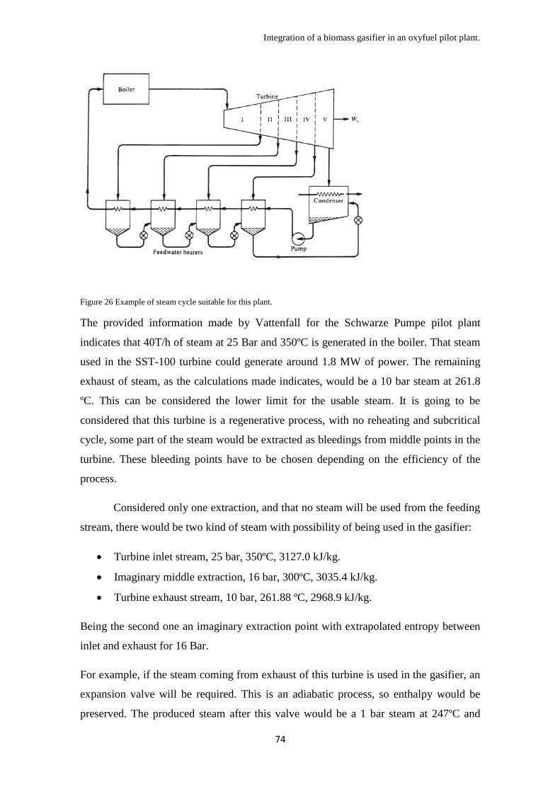
Integration of a biomass gasifier in an oxyfuel pilot plant.
74
Figure 26 Example of steam cycle suitable for this plant.
The provided information made by Vattenfall for the Schwarze Pumpe pilot plant
indicates that 40T/h of steam at 25 Bar and 350ºC is generated in the boiler. That steam
used in the SST-100 turbine could generate around 1.8 MW of power. The remaining
exhaust of steam, as the calculations made indicates, would be a 10 bar steam at 261.8
ºC. This can be considered the lower limit for the usable steam. It is going to be
considered that this turbine is a regenerative process, with no reheating and subcritical
cycle, some part of the steam would be extracted as bleedings from middle points in the
turbine. These bleeding points have to be chosen depending on the efficiency of the
process.
Considered only one extraction, and that no steam will be used from the feeding
stream, there would be two kind of steam with possibility of being used in the gasifier:
Turbine inlet stream, 25 bar, 350ºC, 3127.0 kJ/kg.
Imaginary middle extraction, 16 bar, 300ºC, 3035.4 kJ/kg.
Turbine exhaust stream, 10 bar, 261.88 ºC, 2968.9 kJ/kg.
Being the second one an imaginary extraction point with extrapolated entropy between
inlet and exhaust for 16 Bar.
For example, if the steam coming from exhaust of this turbine is used in the gasifier, an
expansion valve will be required. This is an adiabatic process, so enthalpy would be
preserved. The produced steam after this valve would be a 1 bar steam at 247ºC and
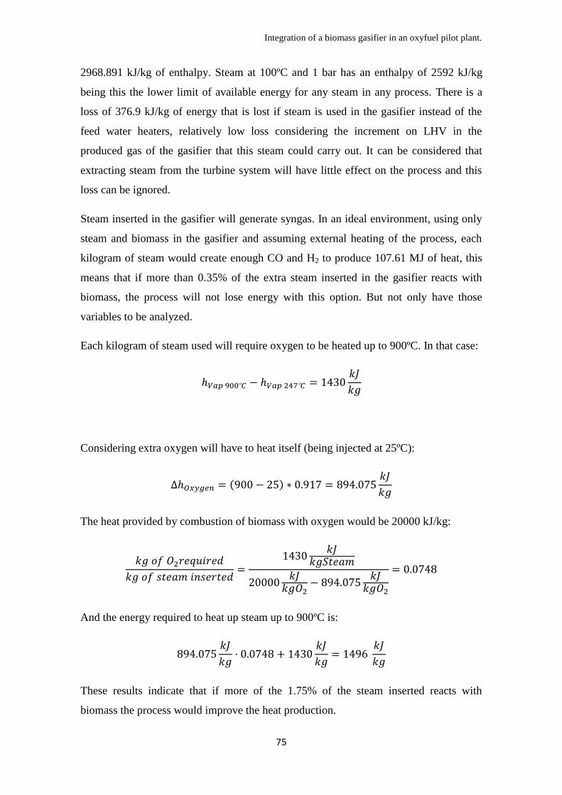
Integration of a biomass gasifier in an oxyfuel pilot plant.
75
2968.891 kJ/kg of enthalpy. Steam at 100ºC and 1 bar has an enthalpy of 2592 kJ/kg
being this the lower limit of available energy for any steam in any process. There is a
loss of 376.9 kJ/kg of energy that is lost if steam is used in the gasifier instead of the
feed water heaters, relatively low loss considering the increment on LHV in the
produced gas of the gasifier that this steam could carry out. It can be considered that
extracting steam from the turbine system will have little effect on the process and this
loss can be ignored.
Steam inserted in the gasifier will generate syngas. In an ideal environment, using only
steam and biomass in the gasifier and assuming external heating of the process, each
kilogram of steam would create enough CO and H2 to produce 107.61 MJ of heat, this
means that if more than 0.35% of the extra steam inserted in the gasifier reacts with
biomass, the process will not lose energy with this option. But not only have those
variables to be analyzed.
Each kilogram of steam used will require oxygen to be heated up to 900ºC. In that case:
Considering extra oxygen will have to heat itself (being injected at 25ºC):
( )
The heat provided by combustion of biomass with oxygen would be 20000 kJ/kg:
And the energy required to heat up steam up to 900ºC is:
These results indicate that if more of the 1.75% of the steam inserted reacts with
biomass the process would improve the heat production.
Integration of a biomass gasifier in an oxyfuel pilot plant.
76
Finally considering the heat of reaction of shift conversion of steam to CO and H2, there
is a total demand of 0.266kg of oxygen and 0.412 kg of biomass per kg of steam
inserted.
Comparing steam and CO2 as reducing agents, for a same LHV generated in the gas
2.41 kg of CO2 would generate same LHV as one kilogram of steam. Considering
reaction of steam up to ten times faster that reaction of biomass with CO2 this
equivalence would be even higher.
The way that steam improves the reaction cannot be analyzed in this project due to the
multiple variables and the low accuracy of kinetic models. It is recommended a deeper
analysis comparing the advantages of using CO2 or steam for this process.
Considering the highest quality product gas as one using lower amount of flue gas from
the paper [22] (Case A on table 4 in chapter 3) there is a total carbon conversion of 0.99,
being the carbon content of the biomass 53.18% p/p (wet basis), a total of 5 kg/h of
biomass is still available that, for the quoted case, does not react during the process.
That biomass can feed 12,135 kg of steam with fuel and unconverted char, but
considering the efficiency of its reaction unknown for this project, it cannot be
evaluated the quantity of steam required for generating a higher LHV gas in the process.
After the previous calculations it can be stated that the idea of using a slipstream from
the turbine system and introduce extra steam looks interesting and is little limited, there
is other options to improve carbon conversion and avoid high carbon content is fly ash
from the gasifier as it can be the pulverization of the woodchips, also it has to be stated
that steam has a great effect on flame stability as it is going to be explained in the next
point.
4.4 Effect of using product gas in the furnace:
Mass flow variations
Considering as it was explained before, a gas is being inserted in the oxyboiler,
the effect that this can carry out is going to be defined in this point. Considering that a
gas with little ashes composed mainly by CO, H2, CO2 and Steam is going to be burnt in
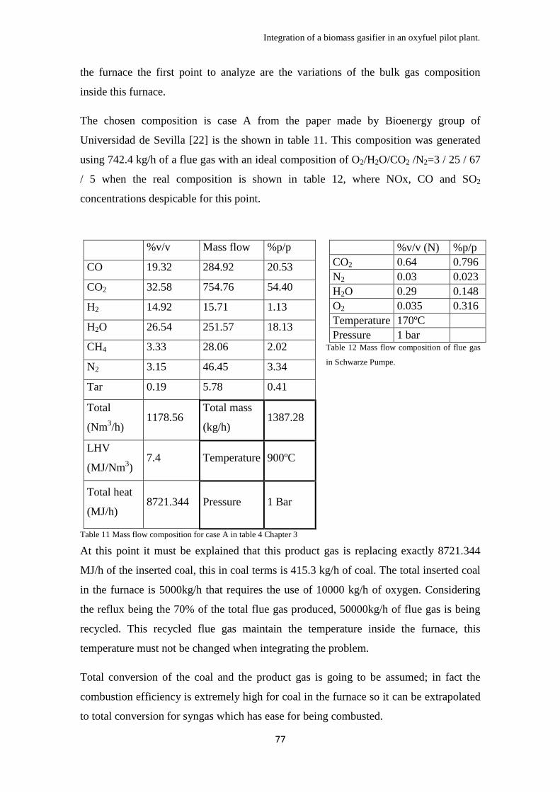
Integration of a biomass gasifier in an oxyfuel pilot plant.
77
the furnace the first point to analyze are the variations of the bulk gas composition
inside this furnace.
The chosen composition is case A from the paper made by Bioenergy group of
Universidad de Sevilla [22] is the shown in table 11. This composition was generated
using 742.4 kg/h of a flue gas with an ideal composition of O2/H2O/CO2 /N2=3 / 25 / 67
/ 5 when the real composition is shown in table 12, where NOx, CO and SO2
concentrations despicable for this point.
%v/v Mass flow %p/p
CO 19.32 284.92 20.53
CO2 32.58 754.76 54.40
H2 14.92 15.71 1.13
H2O 26.54 251.57 18.13
CH4 3.33 28.06 2.02
N2 3.15 46.45 3.34
Tar 0.19 5.78 0.41
Total
(Nm3/h)
1178.56 Total mass
(kg/h) 1387.28
LHV
(MJ/Nm3)
7.4 Temperature 900ºC
Total heat
(MJ/h) 8721.344 Pressure 1 Bar
Table 11 Mass flow composition for case A in table 4 Chapter 3
%v/v (N) %p/p
CO2 0.64 0.796
N2 0.03 0.023
H2O 0.29 0.148
O2 0.035 0.316
Temperature 170ºC
Pressure 1 bar Table 12 Mass flow composition of flue gas
in Schwarze Pumpe.
At this point it must be explained that this product gas is replacing exactly 8721.344
MJ/h of the inserted coal, this in coal terms is 415.3 kg/h of coal. The total inserted coal
in the furnace is 5000kg/h that requires the use of 10000 kg/h of oxygen. Considering
the reflux being the 70% of the total flue gas produced, 50000kg/h of flue gas is being
recycled. This recycled flue gas maintain the temperature inside the furnace, this
temperature must not be changed when integrating the problem.
Total conversion of the coal and the product gas is going to be assumed; in fact the
combustion efficiency is extremely high for coal in the furnace so it can be extrapolated
to total conversion for syngas which has ease for being combusted.

Integration of a biomass gasifier in an oxyfuel pilot plant.
78
CO2, steam and N2 are the main inert used in this combustion process, the produced gas
is feeding by itself 754 kg/h of CO2, 252kg/h of steam and 46 kg/h of N2, being the total
inert introduced 1053 kg/h. This replaces the 2% of the recirculation stream if similar
thermodynamic characteristics are assumed, considering the heat dilution capacity of all
inert introduced as the same.
The flue gas required in the gasifier is 742.4 kg/h of a flue gas with different
composition of the oxyboiler on analyzed in this project, but that composition is that
similar to the flue gas composition in [22] that the resulting gas is going to be
considered unvaried.
With these modifications, FGD and FGC units will treat only 310.6 kg/h of extra flue
gas, meaning an extra treatment of 2.07%, impact that should be evaluated.
Oxygen requirement for coal decreases proportionally 830,6 kg/h but the requirement of
oxygen of the product gas inserted is 665,41kg/h, this means that the integration of this
process requires 9834,81 kg/h of oxygen instead of 10000kg/h required with no
integration.
While integrating the process, the product gas introduces in the furnace 284.92 kg/h of
CO, 251.5 kg/h of H2, 28.06 kg/h of CH4 and 5.78 kg/h of tar, assumed this one as
C6H6.2O0.2 [22]. After combustion these gases will be converted into CO2 and steam.
Complete combustion is going to be considered in this process, this combustion will
vary the composition of the flue gas as it is shown in table 13.
Component
Before
combustión
(kg/h)
After
combustión
(kg/h)
Composition
(%v/v)
Standard
flue gas
(%v/v)
Modified
flue gas
(%v/v)
CO 284.92 0 0 0 0
CO2 754.76 1298.46 0.719 0.796 0.794
H2 15.71 0 0 0 0
H2O 251.57 460.07 0.255 0.148 0.1501
CH4 28.06 0 0 0 0
N2 46.45 46.45 0.0257 0.03 0.0299
TAR
(C6H6.2O0.2) 5.78 0 0 0 0
Table 13 Product gas composition and its effect on the flue gas composition generated after furnace.
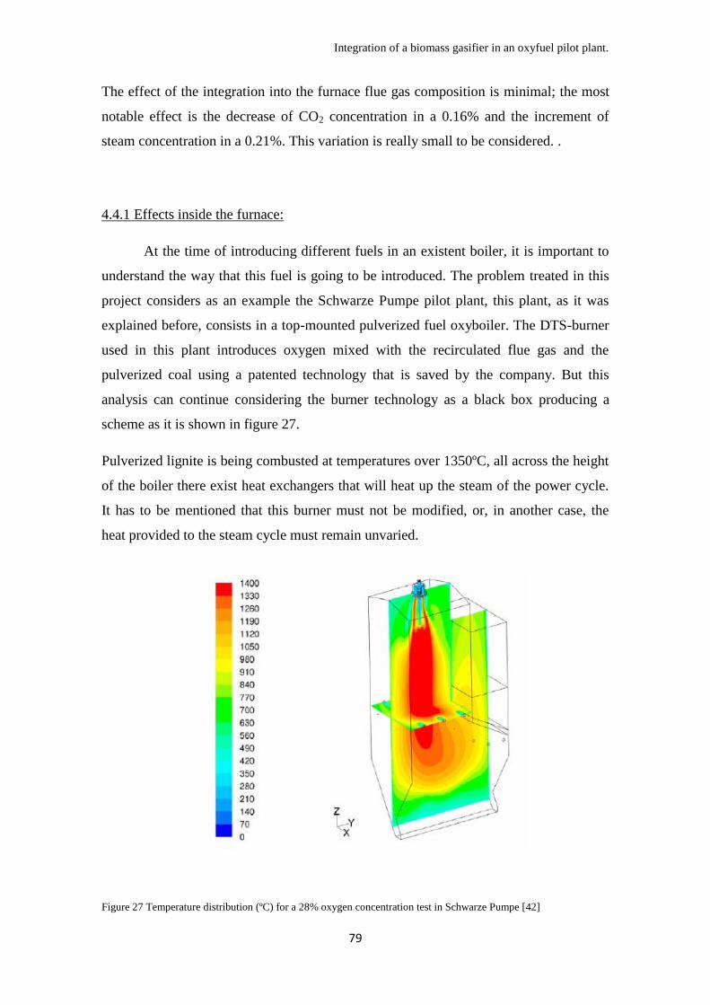
Integration of a biomass gasifier in an oxyfuel pilot plant.
79
The effect of the integration into the furnace flue gas composition is minimal; the most
notable effect is the decrease of CO2 concentration in a 0.16% and the increment of
steam concentration in a 0.21%. This variation is really small to be considered. .
4.4.1 Effects inside the furnace:
At the time of introducing different fuels in an existent boiler, it is important to
understand the way that this fuel is going to be introduced. The problem treated in this
project considers as an example the Schwarze Pumpe pilot plant, this plant, as it was
explained before, consists in a top-mounted pulverized fuel oxyboiler. The DTS-burner
used in this plant introduces oxygen mixed with the recirculated flue gas and the
pulverized coal using a patented technology that is saved by the company. But this
analysis can continue considering the burner technology as a black box producing a
scheme as it is shown in figure 27.
Pulverized lignite is being combusted at temperatures over 1350ºC, all across the height
of the boiler there exist heat exchangers that will heat up the steam of the power cycle.
It has to be mentioned that this burner must not be modified, or, in another case, the
heat provided to the steam cycle must remain unvaried.
Figure 27 Temperature distribution (ºC) for a 28% oxygen concentration test in Schwarze Pumpe [42]

Integration of a biomass gasifier in an oxyfuel pilot plant.
80
It is assumed that a dusty gas with steam and tar, as the produced gas threaten in this
project, must not be introduced into the boiler using the same burner as coal, because
this will reduce efficiency and problems in the burner itself, the primary gas that carries
the coal is a really clean gas with no steam or particles in order not to block the burner,
requirements that the produced gas does not accomplish. But in the other hand still has
to be analyzed which kind of advantages could carry out the introduction at the same
time of both fuels in the process.
Another burner should be design for this biomass derived gas, and an analysis of the
environment must be made.
Many authors have investigated the combustion characteristics of biomass produced
syngas [53][54][55] but there is not any information about the combustion
characteristics of syngas with tar and steam diluted in CO2 in a oxycombustion
chamber, even more, co-fired with coal. Just some information of related experiments
could be gathered in order to create a basis for further investigations.
In order to understand the characteristics of this combustion it has to be analyzed from
the very basics. The gas analyzed here is syngas diluted in CO2 and Steam. Syngas
combustions can reach temperatures over 2000ºC when using air, this temperature will
be much higher using pure oxygen, this means that, as it happens with pulverized coal,
the dilutant concentration is key at the time of controlling the combustion and not to
reach really hot and quick flames that decreases the efficiency of the heat exchangers
and damages the facility.
There exist two key factors related with the design of this facility:
Composition of gases related:
It is important to note, high concentrations of oxygen in the burner will create
really quick and hot flames that cause problems, low concentrations may generate
unburned compounds that cause downstream problems.
Also composition of the gas has to be analyzed precisely. H2/CO yield, tar concentration
and CH4 concentration define the flame that is going to appear in the furnace giving
different characteristics to this one.
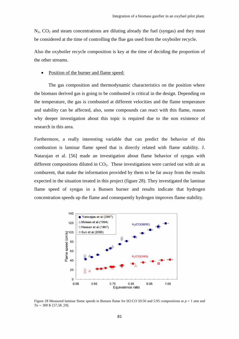
Integration of a biomass gasifier in an oxyfuel pilot plant.
81
N2, CO2 and steam concentrations are diluting already the fuel (syngas) and they must
be considered at the time of controlling the flue gas used from the oxyboiler recycle.
Also the oxyboiler recycle composition is key at the time of deciding the proportion of
the other streams.
Position of the burner and flame speed:
The gas composition and thermodynamic characteristics on the position where
the biomass derived gas is going to be combusted is critical in the design. Depending on
the temperature, the gas is combusted at different velocities and the flame temperature
and stability can be affected, also, some compounds can react with this flame, reason
why deeper investigation about this topic is required due to the non existence of
research in this area.
Furthermore, a really interesting variable that can predict the behavior of this
combustion is laminar flame speed that is directly related with flame stability. J.
Natarajan et al. [56] made an investigation about flame behavior of syngas with
different compositions diluted in CO2. These investigations were carried out with air as
comburent, that make the information provided by them to be far away from the results
expected in the situation treated in this project (figure 28). They investigated the laminar
flame speed of syngas in a Bunsen burner and results indicate that hydrogen
concentration speeds up the flame and consequently hydrogen improves flame stability.
Figure 28 Measured laminar flame speeds in Bunsen flame for H2:CO 50:50 and 5:95 compositions at p = 1 atm and
Tu ∼ 300 K [57,58 ,59].
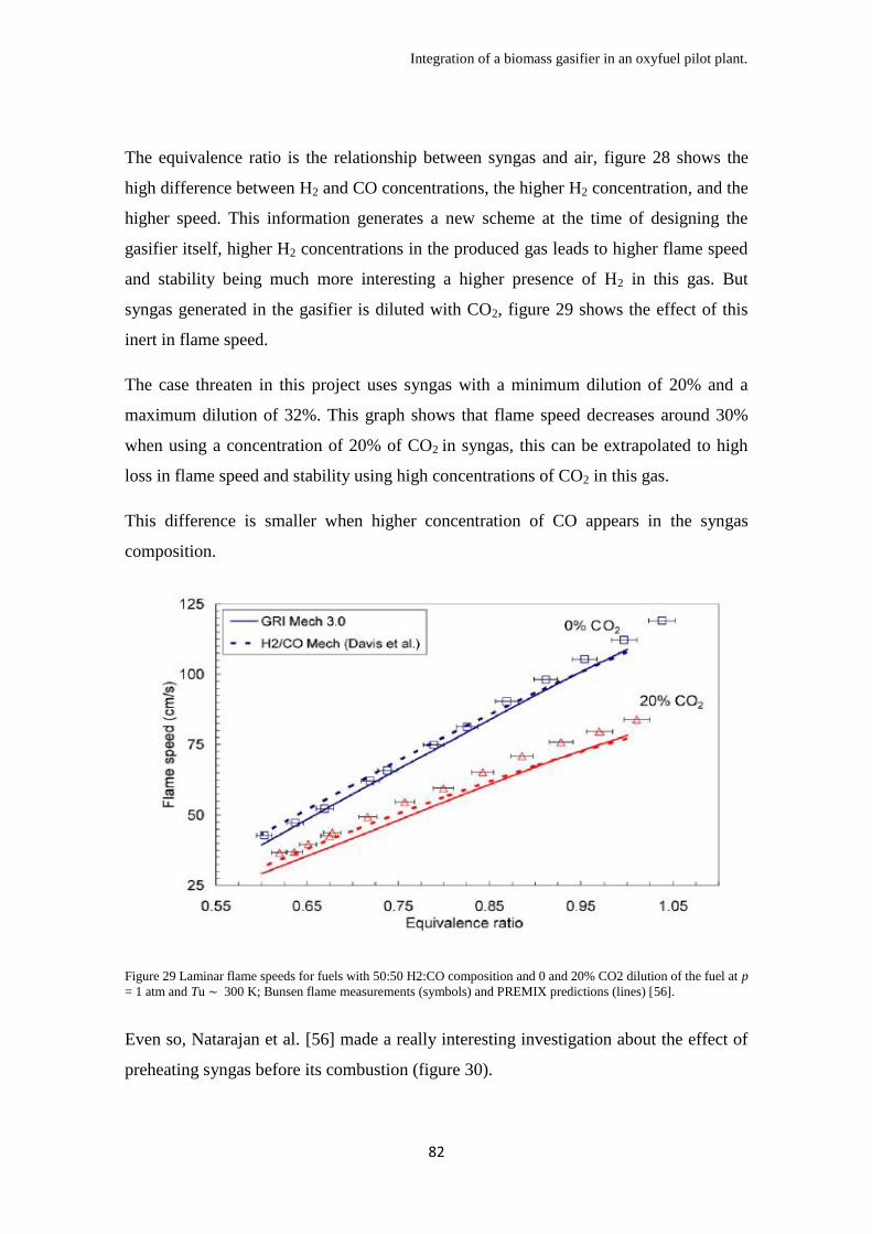
Integration of a biomass gasifier in an oxyfuel pilot plant.
82
The equivalence ratio is the relationship between syngas and air, figure 28 shows the
high difference between H2 and CO concentrations, the higher H2 concentration, and the
higher speed. This information generates a new scheme at the time of designing the
gasifier itself, higher H2 concentrations in the produced gas leads to higher flame speed
and stability being much more interesting a higher presence of H2 in this gas. But
syngas generated in the gasifier is diluted with CO2, figure 29 shows the effect of this
inert in flame speed.
The case threaten in this project uses syngas with a minimum dilution of 20% and a
maximum dilution of 32%. This graph shows that flame speed decreases around 30%
when using a concentration of 20% of CO2 in syngas, this can be extrapolated to high
loss in flame speed and stability using high concentrations of CO2 in this gas.
This difference is smaller when higher concentration of CO appears in the syngas
composition.
Figure 29 Laminar flame speeds for fuels with 50:50 H2:CO composition and 0 and 20% CO2 dilution of the fuel at p
= 1 atm and Tu ∼ 300 K; Bunsen flame measurements (symbols) and PREMIX predictions (lines) [56].
Even so, Natarajan et al. [56] made a really interesting investigation about the effect of
preheating syngas before its combustion (figure 30).

Integration of a biomass gasifier in an oxyfuel pilot plant.
83
Figure 30 Laminar flame speed for fuels with 50:50 H2:CO composition for various preheat temperatures at p = 1
atm; Bunsen flame measurements (symbols) and PREMIX predictions (lines) [56].
In figure 30, Tu is the preheating temperature, feeding temperature of syngas (50:50)
combusted. Considering that the gas generated in the gasifier flows into the furnace at
900ºC, flame speed will be improved due to this.
At this point, three key aspects will define the flame characteristics of this combusted
syngas, H2/CO yield, CO2 dilution and preheat temperature, apart from the equivalence
ratio and mass flow of oxidant and fuel.
But the gas analyzed in this project is not only diluted syngas; it is biomass produced
syngas that, as it has been already explained, contains high amount of steam and tar.
Considering steam (for wet flue gas gasification) being in a concentration from 13(with
small reducing agent concentration in the gasifier or case A from table 4 in chapter 3) to
20 % v/v (with high reducing agent concentration in the gasifier or case B from table 4
in chapter 3) in this gas, and a tar concentration of 0.13 (Case B) to 0.20 % v/v (Case
A), an analysis of these two components have to be made.
Mujanat et Al. [60] made an investigation about the effect of steam and tar in laminar
flame speed of biomass gas. They considered tar as benzene vapor in order to simplify
the average tar. The used gas was gasified woodchips with air, generating a
considerably low heating value gas with high concentrations of nitrogen and carbon
dioxide.

Integration of a biomass gasifier in an oxyfuel pilot plant.
84
In terms of tar effect their results were not as interesting as it was expected (figure 31).
Figure 31 Variation of laminar flame speeds of GBG–air mixture with C6H6 vapor addition. [60].
Tar compounds, in high concentration, accelerates the laminar flame speed of the
combustion of syngas, while it slightly decreases speed in medium concentration. The
gas considered in this project does not reach the values analyzed by [60], meaning that
this effect can be ignored at this point in a first view, but it has to be reminded that tar is
a variety of different compounds, using benzene vapor is a really general assumption,
other compounds could affect in a different way the laminar flame speed meaning that a
deeper investigation in this area could be recommended.
But the effect of steam in flame speed was not despicable as it is shown in figure 32.
While equivalent ratio is close to 1, steam concentration over 4% v/v laminar flame
speed decreases due to the reduction on heat release and the increment of the gas heat
capacity.
Figure 32 Influence of H2O vapor on the laminar flame speed of GBG–air mixture.
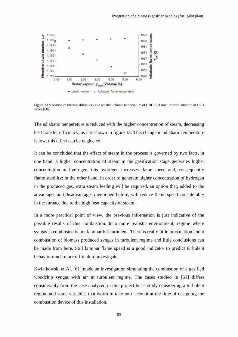
Integration of a biomass gasifier in an oxyfuel pilot plant.
85
Figure 33 Variation of thermal diffusivity and adiabatic flame temperature of GBG fuel mixture with addition of H2O
vapor [60].
The adiabatic temperature is reduced with the higher concentration of steam, decreasing
heat transfer efficiency, as it is shown in figure 33. This change in adiabatic temperature
is low, this effect can be neglected.
It can be concluded that the effect of steam in the process is governed by two facts, in
one hand, a higher concentration of steam in the gasification stage generates higher
concentration of hydrogen, this hydrogen increases flame speed and, consequently
flame stability; in the other hand, in order to generate higher concentration of hydrogen
in the produced gas, extra steam feeding will be required, an option that, added to the
advantages and disadvantages mentioned before, will reduce flame speed considerably
in the furnace due to the high heat capacity of steam.
In a more practical point of view, the previous information is just indicative of the
possible results of this combustion. In a more realistic environment, regime where
syngas is combusted is not laminar but turbulent. There is really little information about
combustion of biomass produced syngas in turbulent regime and little conclusions can
be made from here. Still laminar flame speed is a good indicator to predict turbulent
behavior much more difficult to investigate.
Kwiatkowski et Al. [61] made an investigation simulating the combustion of a gasified
woodchip syngas with air in turbulent regime. The cases studied in [61] differs
considerably from the case analyzed in this project but a study considering a turbulent
regime add some variables that worth to take into account at the time of designing the
combustion device of this installation.
Integration of a biomass gasifier in an oxyfuel pilot plant.
86
It has to be considered that the biomass syngas studied in here contains dilutants and
fuel at the same time and is produced at temperatures over 900ºC, this means that
premixing this gas with oxygen is highly risky. This mixture can burn spontaneously at
these conditions; that is the reason why non-premixed mode is mandatory for this case.
In non-premixed combustion modeling for turbulent regime, the way of controlling the
flame depends on the position of the stoichiometric line and the gradient of fuel and
oxidizer. These two variables are tracked at the same time by the scalar dissipation rate.
In their study they concluded that mixture fraction and scalar dissipation rate defines the
flame temperature and consequently the efficiency of the process. That is the reason
why a study on diffusion effects must be made in order to correlate the behavior of the
flame at turbulent conditions with the composition of the syngas introduced at the time
of considering a turbulent regime.
4.4.2 Energy and mass balance:
Calculation of mass and heat balances in this integration process provides quite
interesting information. It was considered two cases, Case A and Case B explained
before. Produced gas in the gasifier for Case A consists in a more fuel concentrated gas
that is the reason of the higher LHV showed in chapter 3. This gas will require higher
amount of inert gases in case of not willing to reach high temperatures in the furnaces.
Case B produces the whole opposite case, it produces a lesser concentrated gas from the
gasifier requiring less inert gases for producing a good working temperatures.
Also an analysis for the case of using steam as an inert in this process was analyzed, this
idea comes from the idea of using extra steam in the gasifier, steam that also can control
the temperature of the furnace.
Calculations were made considering that the reaction takes place in a perfect mixing
reactor in order to simplify them, this reactor would work at 1400ºC, the flue gas
considered would be the flue gas analyzed in Schwarze Pumpe (O2/H2O/CO2 /N2=3 / 25
/ 67 / 5 at 180ºC and 1 Bar), steam was considered at 900ºC considering that it reach
that temperature in the gasifier.

Integration of a biomass gasifier in an oxyfuel pilot plant.
87
The required mass flow of gases dedicated to dissipate the temperature inside the
furnace (carbon dioxide and steam considered for this point as inerts) was calculated for
each case and each inert in order to achieve conclusions in the complicated topic of the
possibility of using extra steam as reducing agent in the gasifier. Results are shown in
table 14.
Massflow of inert. Case A Case B
Using flue gas as inert. 5048.80 kg/h
4171.11 kg/h
Using steam as inert. 6401.54 kg/h
5288.70 kg/h
Table 14 Inert requirement for maintaining the temperature of the process at 1400ºC inside the furnace considering
independent combustion of syngas inside it.
The results indicates that the range of inert required for reaching temperatures around
1400ºC is seven times larger than the mass flow of gas produced in the gasifier, that
indicates that flue gas will be used for controlling temperature in every case because it
is impossible to use a mass flow of more than 5000 kg/h of steam in the gasifier, it still
can be used as an improvement for the H2 yield but its effect on the temperature control
is small.
These results also indicates what it was already expected, Case A requires more inert
that Case B, and the higher Cp of steam (1.865 kJ/kgK) compared with the oxyboiler
flue gas (0.969 kJ/kgK) could make the reader think that less steam would be required
to maintain temperature in the boiler if it is compared with flue gas, but the difference
of the inlet temperature (900ºC for steam; 180ºC for flue gas) make necessary more
steam for the same case.
As conclusion, the only difference between Case A and Case B, in terms of energy
balance is the higher carbon conversion of Case A compared to Case B, because LHV
can be assumed as only energy density and the inert gases in the produced gas would act
also as inert in the furnace. This carbon conversion can avoid problems in ash
management but in case of requiring conversion over 99%, still extra steam option can
be considered as viable.
It is concluded that a flue gas must be mixed with the produced gas before combustion
in the furnace, this mixing would decrease flame speed and stability.

Integration of a biomass gasifier in an oxyfuel pilot plant.
88
4.4.3 CO2 balance:
The main objective of this project was, as it was said in the introduction, to
generate a process that consumes CO2. After this investigation a general mass balance
can be done in terms of CO2. Woodchips used have 52.78% p/p of carbon, meaning an
introduction of green carbon of 0.2449 t/h, translated into 0.898 t/h of CO2 captured
from environment due to the biomass used. Still the production of CO2 does not vary
largely, case A used 4.6538 t/h of coal and case B used 4.6535 t/h of coal. It can be
considered that both cases still use same coal being this one 4.654 t/h. Most of the
changes that can be applied to the process are internal, general mass balance does not
vary with different recirculation of flue gas or different slipstream for feeding the
gasifier.
This coal that is combusted in the oxyfuel process, generates a total of 10.238 t/h of
CO2 that summed to the CO2 generated by biomass creates a total of 11.1368 t/h of
CO2, 0.1368 t/h more that using the oxyfuel process without the integration of the
gasification stage.
The lower heating value of biomass compared to coal generate more CO2 for producing
the same power (30 MWth), this means that the revenue perceived for consuming 0.898
t/h of CO2 must be higher that the price of capturing 0.1368 t/h of CO2.
Vattenfall stated the cost of avoidance of one ton of CO2 by CCS on its plant in a
arrange of 20-25€ [40], the price of EUA can be considered around 10€ per ton, in
general terms, considering that this plant consumes 0.898 t/h of CO2, it can be assumed,
without considering CER, that close to 9 €/h are being received for CO2 consumption
while 3.25€/h are being invested on capturing extra CO2.
Integrating a gasifier in an oxyfuel process, in terms of CO2, generates a revenue of 5.75
€/h considering that 10€/h per ton of CO2 consumed are being received as emission
right sale and 25 €/h as the price of capturing one ton of CO2. This 5.75 €/h refers as a
total revenue using 0.5 t/h of woodchips, these woodchips would cost from 15 € to 30 €
depending on the quality of the woodchips (data from skytrading Spain). There exists
already economical loses implementing this technology in an industrial plant even with
no consideration of initial and working costs of the facility.
Integration of a biomass gasifier in an oxyfuel pilot plant.
89
In order to achieve zero economical loses with this integration, EUA prices would have
to rise faster than biomass prices, and also coal price would have to increase in a
considerable way to consider this option a reality for the incoming years.
4.5 Gasifier scale up
The whole analysis done in this project until this point has used as basis the idea
that only around the 10% of the total power generated in the plant derives from the
gasifier. A new analysis is going to be done at this part of the project, the effect of
scaling up the size of the gasifier integrated in the oxyfuel plant. This is a proximate
analysis and results still cannot be defined as trustable but they will prepare a basis for
further conclusions. Maintaining the total output of power at 30 MWth, the size of the
gasifier will be varied from 500 kg/h to 3000 kg/h of gasified woodchips, meaning a
power output of the gasifier from 2 MWth to 12 MWth, in this last case the 40% of the
total power.
For this analysis, it is assumed that there no existence of extra feeding of steam inside
the gasifier and the effect of this scale up will be considered regarding the changes
inside the oxyfuel process; the gasifier is assumed to have proportional characteristics at
the time of being scaled up, fluid dynamics inside the fluidized bed are considered
unvaried for this analysis. In all situations, variations regarding the gasifier produced
gas are being ignored due to the fact that only the proportional increment of the mass
flow of every component is the mayor change for these variables.
During this scaling up, both cases (A and B from table 4 in chapter 3) where analyzed,
and a total of 11 different values of woodchip feeding was also investigated. The scale
up is done calculating the total mass flow of each component of the gasified biomass for
ten different new biomass inlet (750, 1000, 1250, 1500, 1750, 2000, 2250, 2500, 2750
and 3000 kg of woodchips per hour). Size of the gasifier is supposed to be increased for
maintaining gas speed and fluid dynamics of the process.
Each of these different feeding for the gasifiers would replace a different quantity of
coal at the oxyfuel plant, this would create a lesser requirement of coal for generating
same power output, this, would change the composition of the oxyboiler.
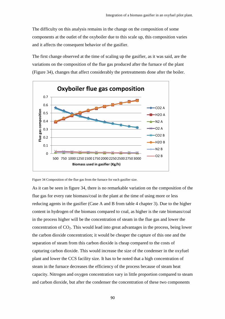
Integration of a biomass gasifier in an oxyfuel pilot plant.
90
The difficulty on this analysis remains in the change on the composition of some
components at the outlet of the oxyboiler due to this scale up, this composition varies
and it affects the consequent behavior of the gasifier.
The first change observed at the time of scaling up the gasifier, as it was said, are the
variations on the composition of the flue gas produced after the furnace of the plant
(Figure 34), changes that affect considerably the pretreatments done after the boiler.
Figure 34 Composition of the flue gas from the furnace for each gasifier size.
As it can be seen in figure 34, there is no remarkable variation on the composition of the
flue gas for every rate biomass/coal in the plant at the time of using more or less
reducing agents in the gasifier (Case A and B from table 4 chapter 3). Due to the higher
content in hydrogen of the biomass compared to coal, as higher is the rate biomass/coal
in the process higher will be the concentration of steam in the flue gas and lower the
concentration of CO2. This would lead into great advantages in the process, being lower
the carbon dioxide concentration; it would be cheaper the capture of this one and the
separation of steam from this carbon dioxide is cheap compared to the costs of
capturing carbon dioxide. This would increase the size of the condenser in the oxyfuel
plant and lower the CCS facility size. It has to be noted that a high concentration of
steam in the furnace decreases the efficiency of the process because of steam heat
capacity. Nitrogen and oxygen concentration vary in little proportion compared to steam
and carbon dioxide, but after the condenser the concentration of these two components
0
0.1
0.2
0.3
0.4
0.5
0.6
0.7
500 750 1000 1250 1500 1750 2000 2250 2500 2750 3000
Flu
e g
as c
om
po
siti
on
Biomass used in gasifier (Kg/h)
Oxyboiler flue gas composition
CO2 A
H2O A
N2 A
O2 A
CO2 B
H2O B
N2 B
O2 B

Integration of a biomass gasifier in an oxyfuel pilot plant.
91
would be higher for high rates biomass/coal, generating possible problems at the time of
capturing carbon dioxide.
Regarding the gasifier, the increment on the steam/CO2 rate would increase the
efficiency of the process due to the better efficiency of gasification reactions related
with steam, this would change the LHV of the gas produced but the effect would not be
high for considering this and improvement due to the high conversion of the process
with 500 kg/h of biomass feeding. But this change on the steam/CO2 rate affects the
behavior of the oxyboiler due to the detriment on efficiency with high steam
concentrations, meaning that the process would not generate the same power for high
biomass/coal rates. Calculating the variations on the gasifier behavior due to this change
is impossible at the time with no empirical investigation, this investigation is
recommended.
Figure 35 shows clearly the variations in the general mass balance of the process. It is
shown in this figure that there is no difference of using case A or case B in these results,
they do not affect the general mass balance. This figure also shows what also figure 34
showed before, more steam has to be condensed for higher rates biomass/coal.
Figure 35 CO2 balance, flue gas produced and steam to be condensed flow rates for each gasifier size.

Integration of a biomass gasifier in an oxyfuel pilot plant.
92
It is also remarkable that for higher rates biomass/coal, similar carbon has to be
captured in total mass flow, this is contrary to figure 34 but it is understandable that it is
required more mass of biomass than coal for generating same power, this is translated
into a higher mass flow of flue gas produced as it is also shown in figure 35. Even so,
the total CO2 generation in the process decreases with a higher rate biomass/coal in the
facility.
Another interesting point is shown in figure 36, recirculation done for maintaining the
temperature constant in the process does not increment considerably for high rates
biomass/coal, neither the requirement of oxygen, but still there is an increment on these
both requirements due to the high flame temperatures that produced gas in the gasifier
provokes and the higher oxygen required for gasification and combustion of the
biomass fed.
Figure 36 Recirculation mass flow and O2 required in the plant for each gasifier size.
In a last point, an analysis of the variations of NOx, SO2 and particles was done. It was
noticed again that there is no effect on the concentration of these components caused by
using case A or B. Figure 37 shows the variation in ppm of the concentration of these
compounds inside the furnace.
0
10000
20000
30000
40000
50000
60000
70000
500 750 1000 1250 1500 1750 2000 2250 2500 2750 3000
Mas
s fl
ow
(kg
/h)
Biomass used in gasifier (kg/h)
Recirculation and oxygen requirement
O2 requirement (kg/h)
Flue gas recycle (kg/h)
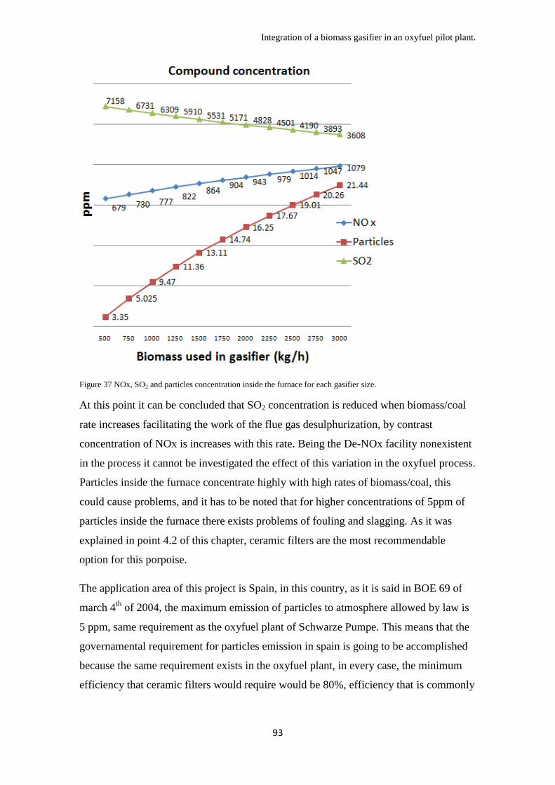
Integration of a biomass gasifier in an oxyfuel pilot plant.
93
Figure 37 NOx, SO2 and particles concentration inside the furnace for each gasifier size.
At this point it can be concluded that SO2 concentration is reduced when biomass/coal
rate increases facilitating the work of the flue gas desulphurization, by contrast
concentration of NOx is increases with this rate. Being the De-NOx facility nonexistent
in the process it cannot be investigated the effect of this variation in the oxyfuel process.
Particles inside the furnace concentrate highly with high rates of biomass/coal, this
could cause problems, and it has to be noted that for higher concentrations of 5ppm of
particles inside the furnace there exists problems of fouling and slagging. As it was
explained in point 4.2 of this chapter, ceramic filters are the most recommendable
option for this porpoise.
The application area of this project is Spain, in this country, as it is said in BOE 69 of
march 4th
of 2004, the maximum emission of particles to atmosphere allowed by law is
5 ppm, same requirement as the oxyfuel plant of Schwarze Pumpe. This means that the
governamental requirement for particles emission in spain is going to be accomplished
because the same requirement exists in the oxyfuel plant, in every case, the minimum
efficiency that ceramic filters would require would be 80%, efficiency that is commonly

Integration of a biomass gasifier in an oxyfuel pilot plant.
94
achieved by these filters, filters that are required in case of rates of biomass/coal higher
than 750/4700.
SO2 is also affected by governmental limitations, for this kind of plant (smaller than 50
MWth) it is required that the emissions are lesser than 200 ppm for a new plant using
solid fuels from biomass but 850 for the general case, with scaling up, this
concentration can be decreased from 7000 ppm to 3600 ppm in the outlet of the furnace
of the plant, considering that the flue gas desulphurization stage has a efficiency of
98.75%, in the worst case the concentration of SO2 would be 87.5 ppm accomplishing
both requirements.
NOx emissions should not emit more than 600 ppm for the Spanish case. This plant
requires a De-NOx stage in any case. It has to be noted that this De-NOx should have a
minimum efficiency of 40% being even not necessary for low biomass/coal rates. As it
was explained previously, Schwarze Pumpe does not have still a De-NOx stage, this
stage will be required only in the case that a gasifier is integrated. This is a remarkable
problem and it has to be taken into account when designing the plant. In any case, after
2016 it will be required a De.NOx plant for every configuration that exceed 500 MWth,
meaning that an industrial design will require this stage if it is erected in Spain.

Integration of a biomass gasifier in an oxyfuel pilot plant.
95
CHAPTER 5: Summary and conclusions:
The integration of a biomass gasifier into an oxyfuel process has been studied in this
project. In general terms, the possibility of creating a carbon negative process is
possible but still not profitable. Costs related with the implementation of the plant and
costs of capturing the CO2 generated differ considerably from the possible revenues
received by EUA and CER.
Still this technology could be implemented in the following years considering a higher
price on coal, an improvement on world economy and a low increment on biomass
prices.
The gasifier analyzed was designed in paper [22] this gasifier uses 500 kg/h of
woodchips as biomass. This biomass is gasified by three components; oxygen, carbon
dioxide and steam. These components are fed into the gasifier using a slipstream of the
flue gas from an oxyfuel plant with the composition shown in table 10 of chapter 4. This
oxyfuel pilot plant uses the gasified biomass as a secondary fuel for co-firing.
The gasifier temperature is maintained at 900ºC; this temperature is maintained by the
combustion of oxygen using the woodchips inside the gasifier. The oxygen provided by
the flue gas analyzed is not enough to maintain that temperature, a stream of pure
oxygen coming from the ASU of the oxyfuel plant is required. The oxygen stream
temperature and composition is known during all the process reason that makes that this
last stream should be the control stream for the working temperature of the gasifier. Due
to the deviations of the composition of the fuel used and the flue gas used, the other
streams are not useful for a PID control system. A control system using this stream is
recommended to maintain the temperature at 900ºC.
The slipstream of the oxyboiler contains other components apart from oxygen, steam
and carbon dioxide. The most remarkable components are NOx, SO2 and particles due
that the most logical slipstream position is place right after de electrostatic precipitator
that contains the oxyfuel plant. In chapter 4 the effect of these components was
analyzed and it was concluded that NOx compounds in the flue gas affect NH3
generation in the gasifier limiting it. Still there is no documents detailing the effect of
extra insertion of NOx in the gasifier but it can be assumed that this NOx would be
converted partly in NH3 that is later on oxidized in the oxyboiler maintaining the same

Integration of a biomass gasifier in an oxyfuel pilot plant.
96
NOx concentration in the process. Effects of NOx in the oxyfuel process is still not
widely analyzed, it is possible that Vattenfall release documents about the topic in a
near future.
SO2 is another remarkable compound contained in the flue gas fed into the gasifier.
Chapter 4 analyzed this component and it was concluded that the low generation of this
compound in the gasifier reduces SO2 concentration at the flue gas after the integration.
But this flue gas is later on fed to the gasifier as gasifying agent, the effect of SO2 inside
the gasifier has not been studied in the bibliography.
Particles during the process were also analyzed, it was concluded that it is necessary the
usage of a flue gas slipstream clean of particles in the gasifier for avoiding fouling and
slagging problems that commonly appear in this kind of process. It was recommended
that the slipstream that would feed the gasifier should be placed right after the
electrostatic precipitator. It was also concluded that the gasified biomass contains high
concentration of particles compared with the concentration that the oxyfuel plant can
hold inside, that creates same problems of slagging and fouling and a cleaning system
for the flue gas was recommended. A cyclone is a good and simple option for this
porpoise. In case of being necessary lower particle concentration or in case of
introducing in the gasifier a biomass with higher ash content, a hot gas secondary
cleaning system is recommended to maintain the thermodynamic efficiency of the
process, the cleaning systems that accomplish these requirements are ceramic candles or
metallic filters.
The possibility of including an extra steam stream for feeding the gasifier was analyzed.
In the oxyfuel plant analyzed does not exists a steam cycle, this cycle was assumed for
the size of this pilot plant. Assuming this, it was examined the possibility of extracting
steam from a bleeding or the exhaust steam of the corresponding turbine. It was noted
that there is no remarkable effect on the thermodynamic efficiency of this cycle because
the heat that the chemical reaction of steam with woodchips release would be always
higher than the heat that feed water heaters of the steam cycle could recover. It was also
concluded that extra steam would improve carbon conversion in the gasifier and H2/CO2
yield would be higher, this would increase the heating value of the gas produced and the
speed and stability that this gas would form inside the furnace. It was also
Integration of a biomass gasifier in an oxyfuel pilot plant.
97
recommended a deeper investigation about this topic due to the little information
existent on the area of biomass gasifiers using multiple gasifying agents.
An analysis of the mass flow variations during the process was analyzed and it was
concluded that there is no remarkable variation on the mass flow and composition of the
streams in the oxyfuel plant meaning that just a little readjustment on the apparatus
would be required in the oxyfuel plant in case of integrating the gasifier.
Combustion of the produced gas inside the furnace of the oxyfuel plant was studied. It
was concluded that, in a first view, it is not recommendable to use this produced gas as
a carrier for the pulverized coal in the furnace due to the high risk of spontaneous
combustion. Also due to the particles and tar that this produced gas could carry it is
recommendable to use a different burner for this gas, this burner should be a non-
premixed burner to avoid spontaneous ignition. It exists still the lack of knowledge in
the effect that this different burner would have inside the furnace, a better cleaning
system would lead into the usage of the same burner for both fuels but the little
information about the burner used in the exemplified pilot plant makes impossible to
analyze this area.
Flame characteristics of the produced gas were analyzed. Higher hydrogen
concentration; lesser carbon dioxide and steam concentration; and higher preheat
temperature improves flame speed and flame stability of the combustion. Tar
concentration is not high enough to consider its effect on flame speed and stability.
Considering that preheat temperature is set to 900ºC only composition of the produced
gas is a variable that could be controlled for favoring flame speed. An analysis of the
steam required in the gasifier for improving this speed is recommended, steam
concentration slows the flame while hydrogen speed it up, it has to be considered that
the gasifier requires more steam for generating more hydrogen, an optimum point must
be researched.
An energy balance for the combustion of the produced gas was made. It was concluded
that inert is required for heat dilution in the flame. There is not enough dilutants in the
produced gas and feeding these dilutants before the gasification stage would decrease
drastically the efficiency of the process. Dilutants feeding must be made right before the
combustion in the furnace but it has to be noted that this dilution decreases flame speed
and stability due to the decrease of the temperature of this stream lowering preheat

Integration of a biomass gasifier in an oxyfuel pilot plant.
98
temperature. It is recommended an analysis of the optimum dilution rate for this
produced gas in order to maintain a relevant efficiency inside the furnace.
There is still lack on knowledge of the effect of preparation of the woodchips used in
the gasifier, it was concluded that thickness of the woodchips used improves
considerably the efficiency of the process.
After the gathering of this information it was excluded the possible idea of direct co-
firing due to the high requirements that an oxyfuel process has. The cleaning system
between gasification and combustion in the furnace provides a control that direct co-
firing does not provide.
Scaling up analysis for the gasifier was done, it was concluded that for power rates up to
12 MWth (40% of the total), and there was considerable variations in the process. It was
concluded that a higher rate of biomass/coal used in the plant increases recycle mass
flow at the plant, requiring a piping redesign; increases flue gas mass flow, requiring an
enlargement of the furnace; increases O2 requirement, provoking a higher oxygen
demand and consequent costs; increases steam concentration at the flue gas, increasing
size of the condenser; and increases particle concentration inserted in the furnace
requiring an extra cleaning system for the produced gas in the gasifier. By contrary, a
higher biomass/coal rate reduces considerably the carbon dioxide produced, reducing
CCS costs and generating higher revenues from EUA due to the higher carbon
consumption, as a secondary benefit, SO2 concentration in the boiler flue gas is reduced,
reducing size and costs of the FGD unit.
It has to be reminded that most of the calculations made in this project were not accurate
enough due to the high number of assumptions that this project has on it.
Recommendations for future investigations were made and the main objective of the
project was achieved. It is also recommended checking the quoted bibliography for
deeper information about each of the topics analyzed here and it is reminded that there
exists widespread investigations being made by scientific community related with this
topic, meaning a constant flow of new results that might be follow in case of being
interested on the creation of a real pilot plant using this technology.

Integration of a biomass gasifier in an oxyfuel pilot plant.
99
Final Summary:
In order to get a better understanding of this project and having a general view of the
conclusions gathered here, the followings tables 15, 16 and 17 are summarizing all the
ideas generated during the creation of this project. After the first preview of the
possibility of the integration of a biomass gasification process into an oxyfuel pilot
plant, many factors are being affected and many recommendations are given for the
clarifying the path to follow at the time of an industrial design of this integration. Table
15 reflexes conclusions regarding the gasifier related to the most important variables,
table 16 reflexes the effect that biomass/coal rate has in this process and table 17
reflexes conclusssions regarding the oxyfuel plant related to the most important
variables.

Integration of a biomass gasifier in an oxyfuel pilot plant.
100
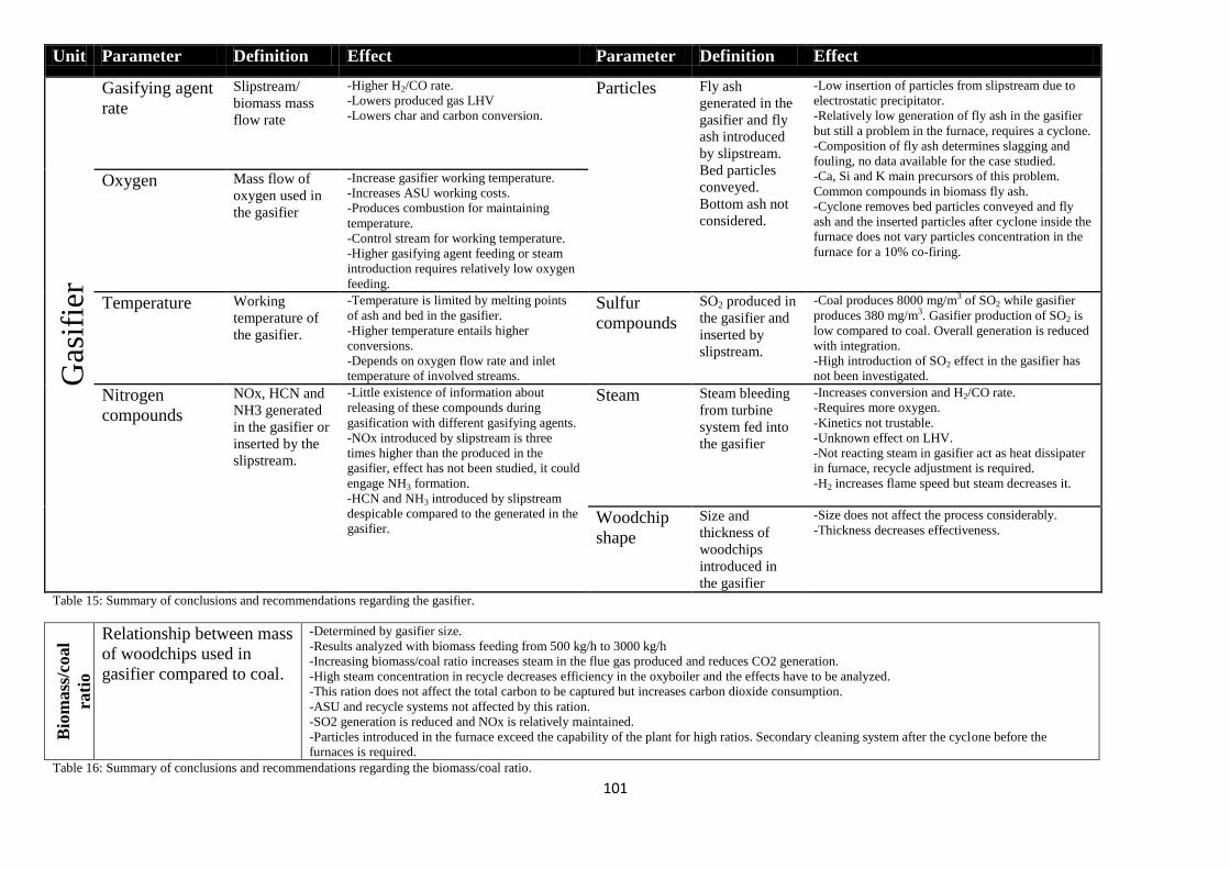
101
Unit Parameter Definition Effect Parameter Definition Effect
Gas
ifie
r Gasifying agent
rate
Slipstream/
biomass mass
flow rate
-Higher H2/CO rate.
-Lowers produced gas LHV
-Lowers char and carbon conversion.
Particles Fly ash
generated in the
gasifier and fly
ash introduced
by slipstream.
Bed particles
conveyed.
Bottom ash not
considered.
-Low insertion of particles from slipstream due to
electrostatic precipitator.
-Relatively low generation of fly ash in the gasifier
but still a problem in the furnace, requires a cyclone.
-Composition of fly ash determines slagging and
fouling, no data available for the case studied.
-Ca, Si and K main precursors of this problem.
Common compounds in biomass fly ash.
-Cyclone removes bed particles conveyed and fly
ash and the inserted particles after cyclone inside the
furnace does not vary particles concentration in the
furnace for a 10% co-firing.
Oxygen Mass flow of
oxygen used in
the gasifier
-Increase gasifier working temperature.
-Increases ASU working costs.
-Produces combustion for maintaining
temperature.
-Control stream for working temperature.
-Higher gasifying agent feeding or steam
introduction requires relatively low oxygen
feeding.
Temperature Working
temperature of
the gasifier.
-Temperature is limited by melting points
of ash and bed in the gasifier.
-Higher temperature entails higher
conversions.
-Depends on oxygen flow rate and inlet
temperature of involved streams.
Sulfur
compounds
SO2 produced in
the gasifier and
inserted by
slipstream.
-Coal produces 8000 mg/m3 of SO2 while gasifier
produces 380 mg/m3. Gasifier production of SO2 is
low compared to coal. Overall generation is reduced
with integration.
-High introduction of SO2 effect in the gasifier has
not been investigated.
Nitrogen
compounds
NOx, HCN and
NH3 generated
in the gasifier or
inserted by the
slipstream.
-Little existence of information about
releasing of these compounds during
gasification with different gasifying agents.
-NOx introduced by slipstream is three
times higher than the produced in the
gasifier, effect has not been studied, it could
engage NH3 formation.
-HCN and NH3 introduced by slipstream
despicable compared to the generated in the
gasifier.
Steam Steam bleeding
from turbine
system fed into
the gasifier
-Increases conversion and H2/CO rate.
-Requires more oxygen.
-Kinetics not trustable.
-Unknown effect on LHV.
-Not reacting steam in gasifier act as heat dissipater
in furnace, recycle adjustment is required.
-H2 increases flame speed but steam decreases it.
Woodchip
shape
Size and
thickness of
woodchips
introduced in
the gasifier
-Size does not affect the process considerably.
-Thickness decreases effectiveness.
Table 15: Summary of conclusions and recommendations regarding the gasifier.
Bio
mass
/coal
rati
o
Relationship between mass
of woodchips used in
gasifier compared to coal.
-Determined by gasifier size.
-Results analyzed with biomass feeding from 500 kg/h to 3000 kg/h
-Increasing biomass/coal ratio increases steam in the flue gas produced and reduces CO2 generation.
-High steam concentration in recycle decreases efficiency in the oxyboiler and the effects have to be analyzed.
-This ration does not affect the total carbon to be captured but increases carbon dioxide consumption.
-ASU and recycle systems not affected by this ration.
-SO2 generation is reduced and NOx is relatively maintained.
-Particles introduced in the furnace exceed the capability of the plant for high ratios. Secondary cleaning system after the cyclone before the
furnaces is required.
Table 16: Summary of conclusions and recommendations regarding the biomass/coal ratio.

Integration of a biomass gasifier in an oxyfuel pilot plant.
102
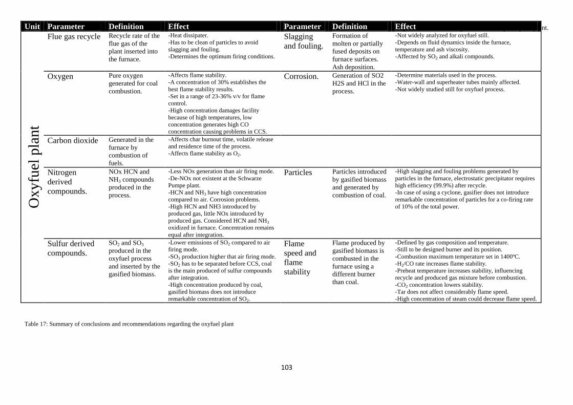
Integration of a biomass gasifier in an oxyfuel pilot plant.
103
Table 17: Summary of conclusions and recommendations regarding the oxyfuel plant
Unit Parameter Definition Effect Parameter Definition Effect
Ox
yfu
el p
lan
t Flue gas recycle Recycle rate of the
flue gas of the
plant inserted into
the furnace.
-Heat dissipater.
-Has to be clean of particles to avoid
slagging and fouling.
-Determines the optimum firing conditions.
Slagging
and fouling.
Formation of
molten or partially
fused deposits on
furnace surfaces.
Ash deposition.
-Not widely analyzed for oxyfuel still.
-Depends on fluid dynamics inside the furnace,
temperature and ash viscosity.
-Affected by SO2 and alkali compounds.
Oxygen Pure oxygen
generated for coal
combustion.
-Affects flame stability.
-A concentration of 30% establishes the
best flame stability results.
-Set in a range of 23-36% v/v for flame
control.
-High concentration damages facility
because of high temperatures, low
concentration generates high CO
concentration causing problems in CCS.
Corrosion. Generation of SO2
H2S and HCl in the
process.
-Determine materials used in the process.
-Water-wall and superheater tubes mainly affected.
-Not widely studied still for oxyfuel process.
Carbon dioxide Generated in the
furnace by
combustion of
fuels.
-Affects char burnout time, volatile release
and residence time of the process.
-Affects flame stability as O2.
Nitrogen
derived
compounds.
NOx HCN and
NH3 compounds
produced in the
process.
-Less NOx generation than air firing mode.
-De-NOx not existent at the Schwarze
Pumpe plant.
-HCN and NH3 have high concentration
compared to air. Corrosion problems.
-High HCN and NH3 introduced by
produced gas, little NOx introduced by
produced gas. Considered HCN and NH3
oxidized in furnace. Concentration remains
equal after integration.
Particles Particles introduced
by gasified biomass
and generated by
combustion of coal.
-High slagging and fouling problems generated by
particles in the furnace, electrostatic precipitator requires
high efficiency (99.9%) after recycle.
-In case of using a cyclone, gasifier does not introduce
remarkable concentration of particles for a co-firing rate
of 10% of the total power.
Sulfur derived
compounds.
SO2 and SO3
produced in the
oxyfuel process
and inserted by the
gasified biomass.
-Lower emissions of SO2 compared to air
firing mode.
-SO3 production higher that air firing mode.
-SO2 has to be separated before CCS, coal
is the main produced of sulfur compounds
after integration.
-High concentration produced by coal,
gasified biomass does not introduce
remarkable concentration of SO2.
Flame
speed and
flame
stability
Flame produced by
gasified biomass is
combusted in the
furnace using a
different burner
than coal.
-Defined by gas composition and temperature.
-Still to be designed burner and its position.
-Combustion maximum temperature set in 1400ºC.
-H2/CO rate increases flame stability.
-Preheat temperature increases stability, influencing
recycle and produced gas mixture before combustion.
-CO2 concentration lowers stability.
-Tar does not affect considerably flame speed.
-High concentration of steam could decrease flame speed.

104
REFERENCES:
[1] COMMUNICATION FROM THE COMMISSION TO THE EUROPEAN PARLIAMENT, THE COUNCIL,
THE EUROPEAN ECONOMIC AND SOCIAL COMMITTEE AND THE COMMITTEE OF THE REGIONS.
Analysis of options to move beyond 20% greenhouse gas emission reductions and assessing the risk of carbon
leakage. European commission. 2010.
[2] Alexandre Kossoy, Philippe Ambrosi. State and trends of the carbon marker. Brochure. www.carbonfinance.org
2010.
[3] Trading in EUAs and Cers. Greenmarket. Brochure. Bayerische Börse. 2010
[4] Carolina García-Martos,Julio Rodríguez,María Jesús Sánchez. Modelling and forecasting fossil fuels, CO2 and
electricity prices and their volatilities. Applied Energy xxx (2012) xxx–xxx (Articles in Press).
[5] Biomass with CO2 Capture and Storage (Bio-CCS). The way forward for Europe. Zero emissions platform.
Brochure. 2012.
[6] Keith D. Sinks, energy crops and land use: coherent climate policy demands an integrated analysis of biomass.
Climatic change, vol. 49(1–2). Netherlands: Springer; 2001. p . 1
[7] Richard Lohwasser, Reinhard Madlener. Economics of CCS for coal plants: Impact of investment costs and
efficiency on market diffusion in Europe. Energy Economics 34 (2012) 850–863.
[8] D.A. Tillman Biomass co_ring: the technology, the experience, the combustion consequences. Biomass and
Bioenergy 19 (2000) 365-384.
[9] IEA Bioenergy. Technical status of biomass co-firing. Fuel 86 (2007) 32–40.
[10] Prabir Basu, James Butler, Mathias A. Leon. Biomass co-firing options on the emission reduction and electricity
generation costs in coal-fired power plants. Fuel Processing Technology 91 (2010) 843–847.
[11] Prabir Basu, James Butler, Mathias A. Leon. Biomass co-firing options on the emission reduction and electricity
generation costs in coal-fired power plants. Renewable Energy 36 (2011) 282-288.
[12] Fouad Al-Mansour, Jaroslaw Zuwala. An evaluation of biomass co-firing in Europe. Biomass and bioenergy 34
(2010) 620–629.
[13] IEA Bioenergy Task 32: Biomass Combustion and Co-firing, Database of Biomass Co-firing.
http://www.ieabcc.nl/
[14] Richard L. Bain, Karl Brior. Wiley series in renewable resources: Thermochemicall procession of biomass;
conversion into fuels, chemicals and power. Wiley,. p 67. 2011.
[15] Arjan F. Kirkels , Geert P.J. Verbong. Biomass gasification: Still promising? A 30-year global overview.
Renewable and Sustainable Energy Reviews 15 (2011) 471–481.
[16] Lijun Wang, Curtis L. Weller, David D. Jones, Milford A. Hanna. Contemporary issues in thermal gasification
of biomass and its application to electricity and fuel production. BIOMASS AND BIOENERGY 32 (2008 ) 573 –
581.
Integration of a biomass gasifier in an oxyfuel pilot plant.
105
[17] Nicholas H. Florin, Andrew T. Harris Hydrogen production from biomass coupled with carbon dioxide capture:
The implications of thermodynamic equilibrium. International Journal of Hydrogen Energy 32 (2007) 4119 – 4134.
[18] U.S. Department of Energy (DoE), National Energy Technology Laboratory (NETL). Gasification – Gasification
database [Exces XLS file]. NETL, the ENERGY lab. [Online] September 2007.
[19] Faaij A. Potential contribution of bioenergy to the world’s future energy demand. s.l.: IEA Bioenergy;
2007.ExCo: 2007:02.
[20] THE GLOBAL STATUS OF CCS | 2012. Brochure. Global CCS institute.
[21] Christopher Highman, Maarten van der Burgt. Gasification. Chapter 6. Second edition 2008.
[22] A. Gómez-Barea, B. Leckner, P. Ollero.INTEGRATION OF A BIOMASS FLUIDIZED BED GASIFIER IN A
COAL OXY-COMBUSTION PLANT. Given by professor.
[23] Priyanka Kaushal, Jalal Abedi, Nader Mahinpey. A comprehensive mathematical model for biomass gasification
in a bubbling fluidized bed reactor. Fuel 89 (2010) 3650–3661.
[24] I.I. Ahmed, A.K. Gupta. Kinetics of woodchips char gasification with steam and carbon dioxide. Applied Energy
88 (2011) 1613–1619.
[25] Y. WANG and C. M. KINOSHITA. KINETIC MODEL OF BIOMASS GASIFICATION. Fuel 84 (2005) 885–
892.
[26] Thilakavathi Mani,NaderMahinpey, PulikesiMurugan. Reaction kinetics and mass transfer studies of biomass
char gasification with CO2.
[27] A. Gómez-Barea, B. Leckner. Modeling of biomass gasification in fluidized bed. . Progress in Energy and
Combustion Science 36 (2010) 444–509.
[28] L. Vandesteene, J.P.Tagutchou, F.J.EscuderoSanz, S.Salvador. Gasification of wood chip particles:
Experimental and numerical study of char–H2O, char–CO2, andchar–O2 reactions. Chemical
EngineeringScience66(2011)4499–4509.
[29] Abraham, B.M., Asbury, J.G., Lynch, E.P., Teotia, A.P.S., 1982. Oil & Gas Journal 80 (11), 68–70.
[30] Gunter Scheffknecht, Leema Al-Makhadmeh1, Uwe Schnell, Jorg Maier. Oxy-fuel coal combustion—A review
of the current state-of-the-art. International Journal of Greenhouse Gas Control 5S (2011) S16–S35.
[31] Terry Wall, Yinghui Liu, Chris Spero, Liza Elliott, Sameer Khare, Renu Rathnam, Farida Zeenathal, Behdad
Moghtaderi, Bart Buhre, Changdong Sheng, Raj Gupta, Toshihiko Yamada, Keiji Makino, Jianglong Y. An overview
on oxyfuel coal combustion—State of the art research and technology development. chemical engineering research
and design 87 (2009) 1003–1016.
[32] Al-Makhadmeh, L., 2009. Coal pyrolysis and char combustion under oxy-fuel conditions. Ph.D.
thesis,University of Stuttgart, Shaker Verlag Aachen.
[33] Shaddix, C.R., Hecht, E.S., Geier, M., Molina, A., Haynes, B.S., 2010. Effect of gasification reactions on oxy-
fuel combustion of pulverized coal char. In: 35th International Technical Conference on Coal Utilization &
FuelSystems, Clearwater.

Integration of a biomass gasifier in an oxyfuel pilot plant.
106
[34] H. Liu, H. Zhu, M. Kaneko, S. Kato, T. Kojima, Energy Fuels 24 (2010) 68–75
[35] Molina, A., Shaddix, R., 2007. Ignition and devolatilization of pulverized bituminous coal particles during
oxygen/carbon dioxide coal combustion. Combustion Institute 31, 1905–1912.
[36] Buhre, B.J.P., Elliott, L.K., Sheng, C.D., Gupta, R.P., Wall, T.F., 2005. Oxy-fuel combustion technology for
coal-fired power generation. Progress in Energy and Combustion Science 31, 283–307.
[37] Kranzmann, A., Hunert, D., Rooch, H., Urban, I., Schulz, W., Osterle, W., 2009. Reactions at the interface
between steel and oxide scale in wet CO2 containing atmospheres. In: NACE International Corrosion Conference and
Expo.
[38] TERMODINÁMICA Y MÁQUINAS TÉRMICAS – UTN REGIONAL BS.AS. – INDUSTRIAL (Ejercicios)
[39] Sebastian Rehfeldt, Christian Kuhr, Franz-Peter Schiffer, Patrick Weckes, Christian Berginsa. First test results of
Oxyfuel combustion with Hitachi’s DST-burner at Vattenfall’s 30 MWth Pilot Plant at Schwarze Pumpe. Energy
Procedia 4 (2011) 1002–1009.
[40] Lars Strömberg, Göran Lindgren, Marie Anheden, Nicklas Simonsson, Moritz Köpcke. Vattenfall’s 30 MWth
Oxyfuel Pilot Plant Project. Vattenfall’s archives.
[41] M. Anheden, U. Burchhardt, H. Ecke, R. Faber, O. Jidinger, R. Giering, H. Kass, S. Lysk, E. Ramström, J. Yan
Overview of Operational Experience and Results from Test Activities in Vattenfall’s 30 MWth Oxyfuel Pilot Plant in
Schwarze Pumpe. Energy Procedia 4 (2011) 941–950.
[42] Lars Strömberg, Göran Lindgren, Jürgen Jacoby, Rainer Giering, Marie Anheden, Uwe Burchhardt, Hubertus
Altmann, Frank Kluger, Georg-Nikolaus Stamatelopoulos. Update on Vattenfall’s 30 MWth Oxyfuel Pilot Plant in
Schwarze Pumpe. Energy Procedia 1 (2009) 581–589.
[43] Oxyfuel power plant process with CO2 capture for zero-emission lignite-based power generation. Vattenfall
Europe. Most, 14.09.2006 Dr.-Ing. Axel Rademacher Vattenfall Europe PowerConsult GmbH.
[44] Jiachun Zhou, Stephen M. Masutani, Darren M. Ishimura, Scott Q. Turn, and Charles M. Kinoshita. Release of
Fuel-Bound Nitrogen during Biomass Gasification. Ind. Eng. Chem. Res. 2000, 39, 626-634.
[45] Cuong Van Huynh, Song-Charng Kong. Performance characteristics of a pilot-scale biomass gasifier using
oxygen-enriched air and steam. Fuel 103 (2013) 987–996.
[46] Anders Hjörnhede, Melanie Montgomery, Martin Bjurman, Pamela Henderson, Alexander Gerhardt.
PRELIMINARY EXPERIENCES WITH MATERIAL TESTING AT THE OXYFUEL PILOT PLANT AT
SCHWARZEPUMPE. Vattenfall’s archive.
[47] Thomas L. Eberhardt, Hui Pan. Analysis of the fly ash from the processing of wood chips in a pilot-scale
downdraft gasifier: Comparison of inorganic constituents determined by PIXE and ICP-AES. Biomass and bioenergy
51 (2013) 163-168.
[48] Hui Pan, Thomas L. Eberhardt. Characterization of fly ash from the gasification of Wood and assessment for
its application as a soil amendment. Peer-previewed articles. www.bioresources.com

Integration of a biomass gasifier in an oxyfuel pilot plant.
107
[49] C. Fernández-Pereira, J.A. de la Casa, A. Gómez-Barea, F. Arroyo, C. Leiva, Y. Luna. Application of biomass
gasification fly ash for brick manufacturing. Fuel 90 (2011) 220–232.
[50] Kristina Göransson, Ulf Söderlind, Jie He, Wennan Zhang. Review of syngas production via biomass DFBG.
Renewable and Sustainable Energy Reviews 15 (2011) 482–492.
[51] S.D. Sharma, M. Dolan, D. Park, L. Morpeth, A. Ilyushechkin, K. McLennan, D.J. Harris, K.V. Thambimuthu A
critical review of syngas cleaning technologies — fundamental limitations and practical problems. Powder Technology
180 (2008) 115–121.
[52] Turbinas de vapor industriales. La gama integral de productos de 2 a 250 MW. Siemens.
[53] Cuong Van Huynh, Song-Charng Kong. Combustion and NOx emissions of biomass-derived syngas under
various gasification conditions utilizing oxygen-enriched-air and steam. Fuel 107 (2013) 455–464.
[54] C. Liu, B. Yan, G. Chen, X.S. Bai. Structures and burning velocity of biomass derived gas flames. International
journal of hydrogen energy 35 (2010)542–555.
[55] Tran Manh Vu, Won Sik Song, Jeong Park, Dae Seok Bae, Hyun Seok You. Measurements of propagation
speeds and flame instabilities in biomass derived gaseair premixed flames. International journal of hydrogen energy
36 (2011) 12058-12067.
[56] J. Natarajan, T. Lieuwen, J. Seitzman . Laminar flame speeds of H2/CO mixtures:Effect of CO2 dilution, preheat
temperature, and pressure. Combustion and Flame 151 (2007) 104–119.
[57] I.C. McLean, D.B. Smith, S.C. Taylor, Proc. Combust. Inst. 25 (1994) 749–757.
[58] M.I. Hassan, K.T. Aung, G.M. Faeth, AIAA paper #96- 0912, 1996.
[59] H.Y. Sun, S.I. Yang, G. Jomass, C.K. Law, Proc. Combust. Inst. 31 (2006) 439–446.
[60] Nur Farizan Munajat, Catharina Erlich, Reza Fakhrai, Torsten H. Fransson. Influence of water vapour and tar
compound on laminar flame speed of gasified biomass gas. Applied Energy 98 (2012) 114–121.
[61] K. KWIATKOWSKI, K. BAJER, K. WĘDOŁOWSKI. Turbulent combustion of biomass syngas. Arch. Mech.,
64, 5, pp. 511–527, Warszawa 2012.

0

0