
Manual de instrucciones original - vogt-tec.de · 5 Mantenimiento y cuidado 6 Solución de...
52
WorkTec Versión: 09/2017 Equipos de aire comprimido VOGT con lista de herramientas, accesorios y piezas de repuesto Manual de instrucciones original ES
Transcript of Manual de instrucciones original - vogt-tec.de · 5 Mantenimiento y cuidado 6 Solución de...
WorkTecVersión: 09/2017
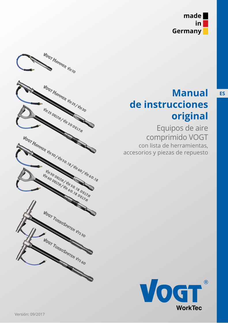
Equipos de aire comprimido VOGT
con lista de herramientas, accesorios y piezas de repuesto
Manual de instrucciones
original
ES
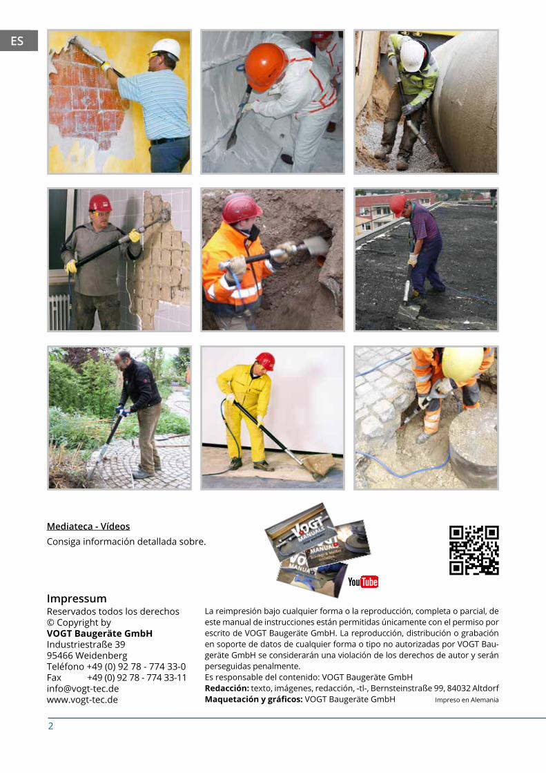
Consiga información detallada sobre.
Mediateca - Vídeos
ImpressumReservados todos los derechos© Copyright byVOGT Baugeräte GmbHIndustriestraße 39 95466 WeidenbergTeléfono +49 (0) 92 78 - 774 33-0Fax +49 (0) 92 78 - 774 [email protected]
La reimpresión bajo cualquier forma o la reproducción, completa o parcial, de este manual de instrucciones están permitidas únicamente con el permiso por escrito de VOGT Baugeräte GmbH. La reproducción, distribución o grabación en soporte de datos de cualquier forma o tipo no autorizadas por VOGT Bau-geräte GmbH se considerarán una violación de los derechos de autor y serán perseguidas penalmente.Es responsable del contenido: VOGT Baugeräte GmbHRedacción: texto, imágenes, redacción, -tl-, Bernsteinstraße 99, 84032 AltdorfMaquetación y gráficos: VOGT Baugeräte GmbH Impreso en Alemania
2Sujeto a modificaciones sin previo aviso
Asesoramiento:+49(0)92 78-774 33-0
+49(0)92 78-774 33-11www.vogt-tec.de
ES
3Sujeto a modificaciones sin previo aviso
Asesoramiento: +49(0)92 78-774 33-0 +49(0)92 78-774 33-11www.vogt-tec.de
ES5
1 Seguridad
4.1 Pausas y fin del trabajo
4 Trabajos
3.2 Conexión de la manguera
3.1 Colocación y cambio de la herramienta
3 Funcionamiento
2 Transporte / almacenamiento
1.3 Obligaciones del operador
1.2 Riesgos residuales
1.1 Uso previsto
5 Mantenimiento y cuidado
6 Solución de problemas
7 Eliminación
8 Datos técnicos
9 Montaje del soporte del raspador
12 Piezas de repuesto
11 Herramientas
10 Montaje del soporte del cono en el alojamiento del cono
Índice de contenido
100%made in Germany
Asesoramiento telefónico
Envío generalmente el mismo día del pedido
Garantía de 24 meses
24meses
13
11
10
9
7
7
7
6
6
6
13
14
15
16
20
23
24
36
EN
EN
EN
EN

4Sujeto a modificaciones sin previo aviso
Asesoramiento:+49(0)92 78-774 33-0
+49(0)92 78-774 33-11www.vogt-tec.de
ES
Validez de las instrucciones
Este manual se debe transportar con el dispositivo.Recomendación: Guardarlo en el bolsillo del maletín de transporteAVISO
Este manual de instrucciones es válido para los siguientes dispositivos:• VOGT Hammer VH10 / VH 25 / VH 30 / VH 50 / VH 50.18 / VH 60 / VH 60.18• VOGT Hammer Delta VH10 / VH 25 / VH 30 / VH 50 / VH 50.18 / VH 60 / VH 60.18• VOGT TurboSpaten VTS 50 / VTS 60
Este manual de instrucciones, además de servir como guía para el equipo básico VTS 50 / VTS 60, es parte del manual de instrucciones de los siguientes dispositivos:• Gama de productos GeoInjector VOGT• Lanza de aire VOGT• Lanza de demolición VOGT
Consulte el albarán de entrega y/o la factura para comprobar el contenido suministrado.
Símbolos utilizados
Las flechas amarillas indican el peligro de daños a la máquina o dan consejos para hacer el trabajo más fácil.AVISO
Peligro de lesiones graves o de muerte.ADVERTENCIA
Las personas pueden sufrir lesiones.ATENCIÓN
El fabricante / tipo (1) y número de serie / año de construcción (2) están gravados en el equipo.
1 2
5Sujeto a modificaciones sin previo aviso
Asesoramiento: +49(0)92 78-774 33-0 +49(0)92 78-774 33-11www.vogt-tec.de
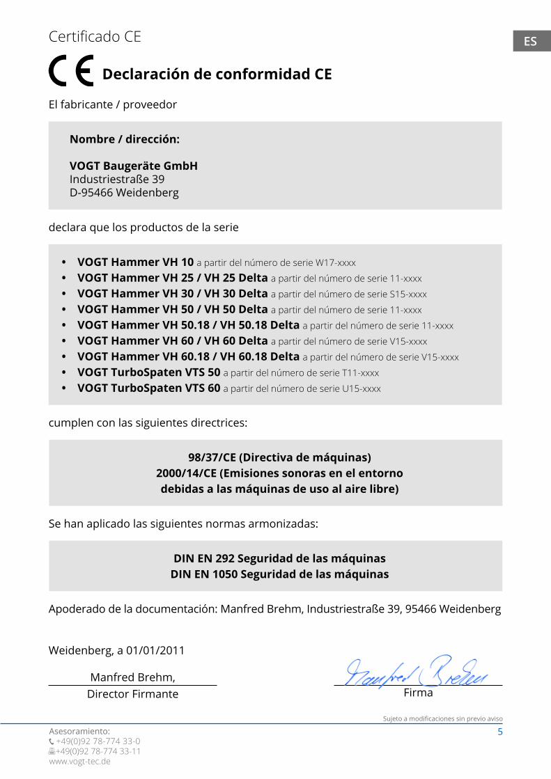
ESCertificado CE
Declaración de conformidad CE
El fabricante / proveedor
declara que los productos de la serie
cumplen con las siguientes directrices:
Se han aplicado las siguientes normas armonizadas:
Apoderado de la documentación: Manfred Brehm, Industriestraße 39, 95466 Weidenberg
Weidenberg, a 01/01/2011
Manfred Brehm, Director Firmante Firma
Nombre / dirección:
VOGT Baugeräte GmbHIndustriestraße 39D-95466 Weidenberg
• VOGT Hammer VH 10 a partir del número de serie W17-xxxx
• VOGT Hammer VH 25 / VH 25 Delta a partir del número de serie 11-xxxx
• VOGT Hammer VH 30 / VH 30 Delta a partir del número de serie S15-xxxx
• VOGT Hammer VH 50 / VH 50 Delta a partir del número de serie 11-xxxx
• VOGT Hammer VH 50.18 / VH 50.18 Delta a partir del número de serie 11-xxxx
• VOGT Hammer VH 60 / VH 60 Delta a partir del número de serie V15-xxxx
• VOGT Hammer VH 60.18 / VH 60.18 Delta a partir del número de serie V15-xxxx
• VOGT TurboSpaten VTS 50 a partir del número de serie T11-xxxx
• VOGT TurboSpaten VTS 60 a partir del número de serie U15-xxxx
98/37/CE (Directiva de máquinas)2000/14/CE (Emisiones sonoras en el entorno debidas a las máquinas de uso al aire libre)
DIN EN 292 Seguridad de las máquinasDIN EN 1050 Seguridad de las máquinas
6Sujeto a modificaciones sin previo aviso
Asesoramiento:+49(0)92 78-774 33-0
+49(0)92 78-774 33-11www.vogt-tec.de
ES
1.1 Uso previsto
1.2 Riesgos residuales
1 Seguridad
Los equipos de aire comprimido de VOGT solo pueden ponerse en marcha, operarse, mantenerse y repararse tal y como se describe en este manual de instrucciones. Las repa-raciones no descritas deben ser realizadas por un taller especializado o por el fabricante.AVISO
Los equipos descritos, en función de la herramienta que se inserta (véase el capítulo 11), son únca-mente adecuados para compactar, hincar, raspar, cortar, romper, arrancar, abujardar, limpiar, excavar y eliminar diferentes materiales. Cualquier otro uso se considera inadecuado y, por tanto, está pro-hibido. Las modificaciones, la inserción de herramientas de terceros, así como mermar o alterar los controles y mandos también está prohibido. Estos equipos no están diseñados para usarse en zonas con riesgo de explosión. Su empleo en zonas con riesgo de explosión está prohibido. Los trabajos que se deban realizar en el agua o debajo del agua también quedan prohibidos. Los equipos no deben usarse si existe riesgo de tener contacto con objetos o líneas eléctricas o si pudieran verse afectados de alguna manera durante la realización de los trabajos. En estos casos, un electricista autorizado y certificado debe dejar sin tensión estos objetos o líneas.
Los equipos de aire comprimido de VOGT solo pueden ser utilizados por personas mayores de edad que se encuentren física y mentalmente capacitadas y que hayan leído y entendido el manual de instrucciones.
Los peligros residuales son peligros que no se pueden eliminar por completo a pesar de que la cons-trucción de estos equipos se haya realizado según las normas de seguridad pertinentes.
Riesgos derivados del ruido.
Use siempre protectores auditivos adecuados.
Dependiendo de los materiales que se procesan, se generan niveles de ruido de di-ferentes intensidades. Estar expuesto durante mucho tiempo a estos niveles puede causar daños permanentes en la audición. ATENCIÓN
Peligros debidos a vibraciones.
Tenga en cuenta los tiempos de encendido permitidos y, en caso necesario, lleve guantes de protección a prueba de vibraciones que estén homologados.
La exposición prolongada del cuerpo humano a las vibraciones puede producir daños físicos permanentes como son el entumecimiento o los daños en el sistema nervioso.
ATENCIÓN
Peligro de lesión debido a esquirlas, material desprendido, polvo y herramientas cortantes.
Use siempre un equipo de protección personal adecuado (p. ej. zapatos de seguridad, ropa ajustada, guantes y gafas de protección, protección especial contra esquirlas y, en caso necesario, mascarilla respiratoria) al realizar trabajos con estos equipos.
Al trabajar con estos equipos las esquirlas pueden provocar lesiones y el polvo puede producir infecciones respiratorias. La caída de objetos puede ocasionar lesiones en la cabeza.
ATENCIÓN
7Sujeto a modificaciones sin previo aviso
Asesoramiento: +49(0)92 78-774 33-0 +49(0)92 78-774 33-11www.vogt-tec.de
ES
1.3 Obligaciones del operador
2 Transporte / almacenamiento
Los equipos de aire comprimido de VOGT solo pueden operarse con aceite comprimido lubricado. Debe evitarse la entrada de suciedad en la línea de aire comprimido.AVISO
El fabricante no puede evaluar cada uno de los posibles riesgos residuales. Estos pe-ligros dependerán únicamente del material específico que se trabaja. La evaluación de riesgos y la adopción de las medidas de seguridad necesarias son responsabilidad exclusiva del operador. A estas obligaciones también pertenece el cumplimiento del plan de seguridad y salud en la obra (SiGe-Plan).
AVISO
3 Funcionamiento
Los equipos de aire comprimido de VOGT se suelen suministrar con un equipo básico de protección personal. Este equipo se compone de de guantes y gafas de protección y protectores auditivos. Queremos hacer especial hincapié en que el equipo de protec-ción personal no protege contra todos los posibles peligros. En cada caso concreto, use siempre el equipo de protección personal prescrito, aprobado y adecuado.
AVISO
• Cumplir las normas aplicables para la prevención de accidentes.• Cumplir las normativas de seguridad y salud vigentes y aplicables.• Instruir al personal operativo con ayuda de este manual.• Garantizar la seguridad de la zona de trabajo.• Proporcionar el equipo de protección personal homologado y necesario.
• Compruebe la ausencia de daños visibles en el equipo, herramientas y accesorios antes de poner en marcha el equipo. Las herramientas que presentan daños no deben utilizarse.
• Informe a un taller especializado, a su distribuidor o al fabricante. Encontrará cualquier número de pedido que necesite en la lista de herramientas que se detalla en el capítulo 11 o en la lista de piezas de repuesto del capítulo 12.
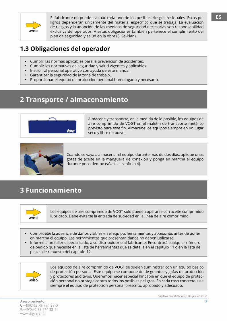
Almacene y transporte, en la medida de lo posible, los equipos de aire comprimido de VOGT en el maletín de transporte metálico previsto para este fin. Almacene los equipos siempre en un lugar seco y libre de polvo.
Cuando se vaya a almacenar el equipo durante más de dos días, aplique unas gotas de aceite en la manguera de conexión y ponga en marcha el equipo durante poco tiempo (véase el capítulo 4).
8Sujeto a modificaciones sin previo aviso
Asesoramiento:+49(0)92 78-774 33-0
+49(0)92 78-774 33-11www.vogt-tec.de
ES
Principio básico: Cuanto menor es la resistencia del material, menor es la presión de servicio. La presión de servicio es demasiado alta si la herramienta se separa del material sin control. La presión excesiva aumenta las vibraciones, lo que reduce el rendimiento de trabajo y provoca daños en el equipo, por ejemplo. Los equipos de aire comprimido de VOGT deben lubricarse continuamente durante su funcionamiento. De lo contrario, el aparato se podría dañar. Se recomienda utilizar el engrasador de líneas de precisión de VOGT (Z 300 S).
Para conectar el equipo de aire comprimido de VOGT a la fuente de aire comprimido (p. ej., un compresor) se necesita una manguera de aire comprimido que tenga un diámetro mínimo interior de 9 mm; como por ejem-plo, el tambor portamanguera de VOGT (Z 100), la manguera de aire comprimido de PU de VOGT (Z 110 S).
Existe el riesgo de daños en el equipo si la presión de servicio en el equipo es superior a 6 bares (87 psi).
Comprobar la presión de servicio y ajustar al valor correcto si es necesario. Si es preciso, utilizar el regulador de presión de VOGT (Z 400 S).
AVISO
Para suministrar aire a un equipo de aire comprimido de VOGT, es suficiente con una fuente de aire com-primido potente (como compresor) de 3 a 6 bares y un caudal efectivo de al menos 190 l/min para VH 25 / VH 30 o de 255 l/min para VH 10, VH50, VH 50.18, VH 60, VH 60.18, VTS 50, VTS 60. Esto corresponde a una capacidad mínima de succión de unos 380-450 l/min. Las fuentes más potentes de aire comprimido se utilizan teniendo en consideración las respectivas presiones de trabajo. Encontrará las presiones de trabajo recomendadas para los diferentes materiales en la tabla del capítulo 8. Si es preciso, utilizar el regulador de presión de VOGT (Z400 S).
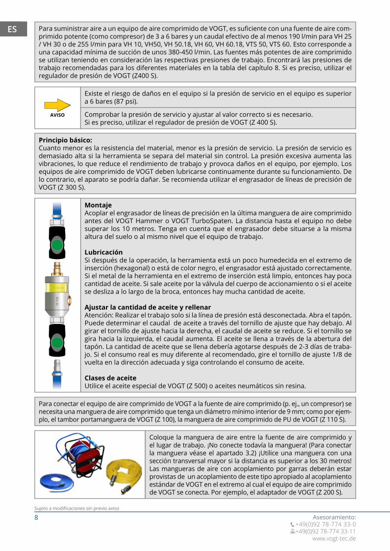
MontajeAcoplar el engrasador de líneas de precisión en la última manguera de aire comprimido antes del VOGT Hammer o VOGT TurboSpaten. La distancia hasta el equipo no debe superar los 10 metros. Tenga en cuenta que el engrasador debe situarse a la misma altura del suelo o al mismo nivel que el equipo de trabajo.
LubricaciónSi después de la operación, la herramienta está un poco humedecida en el extremo de inserción (hexagonal) o está de color negro, el engrasador está ajustado correctamente. Si el metal de la herramienta en el extremo de inserción está limpio, entonces hay poca cantidad de aceite. Si sale aceite por la válvula del cuerpo de accionamiento o si el aceite se desliza a lo largo de la broca, entonces hay mucha cantidad de aceite.
Ajustar la cantidad de aceite y rellenarAtención: Realizar el trabajo solo si la línea de presión está desconectada. Abra el tapón. Puede determinar el caudal de aceite a través del tornillo de ajuste que hay debajo. Al girar el tornillo de ajuste hacia la derecha, el caudal de aceite se reduce. Si el tornillo se gira hacia la izquierda, el caudal aumenta. El aceite se llena a través de la abertura del tapón. La cantidad de aceite que se llena debería agotarse después de 2-3 días de traba-jo. Si el consumo real es muy diferente al recomendado, gire el tornillo de ajuste 1/8 de vuelta en la dirección adecuada y siga controlando el consumo de aceite.
Clases de aceiteUtilice el aceite especial de VOGT (Z 500) o aceites neumáticos sin resina.
Coloque la manguera de aire entre la fuente de aire comprimido y el lugar de trabajo. ¡No conecte todavía la manguera! (Para conectar la manguera véase el apartado 3.2) ¡Utilice una manguera con una sección transversal mayor si la distancia es superior a los 30 metros! Las mangueras de aire con acoplamiento por garras deberán estar provistas de un acoplamiento de este tipo apropiado al acoplamiento estándar de VOGT en el extremo al cual el equipo de aire comprimido de VOGT se conecta. Por ejemplo, el adaptador de VOGT (Z 200 S).
9Sujeto a modificaciones sin previo aviso
Asesoramiento: +49(0)92 78-774 33-0 +49(0)92 78-774 33-11www.vogt-tec.de
ES
3.1 Colocación y cambio de la herramienta
Colocación de la herramienta
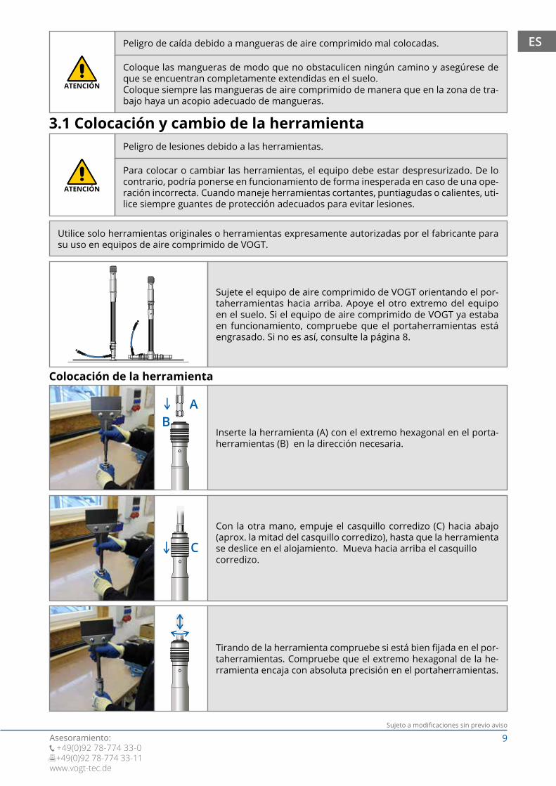
AB
Inserte la herramienta (A) con el extremo hexagonal en el porta-herramientas (B) en la dirección necesaria.
C
Con la otra mano, empuje el casquillo corredizo (C) hacia abajo (aprox. la mitad del casquillo corredizo), hasta que la herramienta se deslice en el alojamiento. Mueva hacia arriba el casquillo corredizo.
Tirando de la herramienta compruebe si está bien fijada en el por-taherramientas. Compruebe que el extremo hexagonal de la he-rramienta encaja con absoluta precisión en el portaherramientas.
Utilice solo herramientas originales o herramientas expresamente autorizadas por el fabricante para su uso en equipos de aire comprimido de VOGT.
Peligro de caída debido a mangueras de aire comprimido mal colocadas.
Coloque las mangueras de modo que no obstaculicen ningún camino y asegúrese de que se encuentran completamente extendidas en el suelo. Coloque siempre las mangueras de aire comprimido de manera que en la zona de tra-bajo haya un acopio adecuado de mangueras.
ATENCIÓN
Peligro de lesiones debido a las herramientas.
Para colocar o cambiar las herramientas, el equipo debe estar despresurizado. De lo contrario, podría ponerse en funcionamiento de forma inesperada en caso de una ope-ración incorrecta. Cuando maneje herramientas cortantes, puntiagudas o calientes, uti-lice siempre guantes de protección adecuados para evitar lesiones.
ATENCIÓN
Sujete el equipo de aire comprimido de VOGT orientando el por-taherramientas hacia arriba. Apoye el otro extremo del equipo en el suelo. Si el equipo de aire comprimido de VOGT ya estaba en funcionamiento, compruebe que el portaherramientas está engrasado. Si no es así, consulte la página 8.

10Sujeto a modificaciones sin previo aviso
Asesoramiento:+49(0)92 78-774 33-0
+49(0)92 78-774 33-11www.vogt-tec.de
ES Cambio de la herramienta
Conecte la manguera a la fuente de aire comprimido (p. ej., el compresor) y abra el suministro de aire comprimido.
Compruebe que las mangueras de aire comprimido y los acoplamientos son estancos. Si hay fugas, ¡interrumpa el suministro de aire comprimido y susti-tuya la manguera!
3.2 Conexión de la manguera
C Empuje el casquillo corredizo (C) hacia abajo hasta llegar a la mitad.
AB
Con la otra mano, saque la herramienta (A).Mueva hacia arriba el casquillo corredizo.
Conecte la manguera al equipo de aire comprimido de VOGT. Al hacerlo, ase-gúrese de que el equipo de aire comprimido no se pone en marcha de forma automática. En caso de que esto ocurra, desconecte de inmediato el acopla-miento del aire comprimido. Solicite a un taller especializado o al fabricante la reparación del equipo de aire comprimido.
Peligro de lesiones debido a herramientas que salen despedidas.
Al cambiar la herramienta, asegúrese de que el portaherramientas no muestra sig-nos importantes de desgaste ni desviaciones notables. También asegúrese de que el extremo hexagonal de la herramienta se encuentra en perfecto estado. Compruebe después de cada cambio que la herramienta está bien apretada.
ATENCIÓN
11Sujeto a modificaciones sin previo aviso
Asesoramiento: +49(0)92 78-774 33-0 +49(0)92 78-774 33-11www.vogt-tec.de
ES
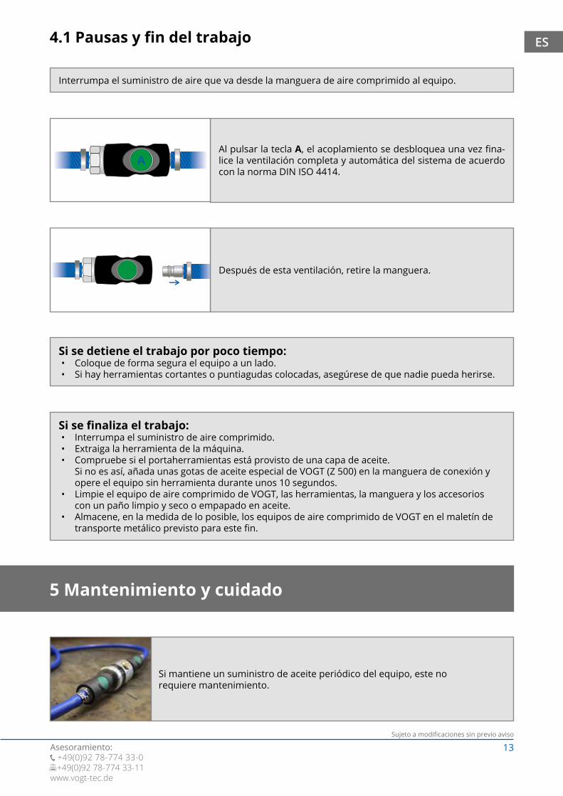
Sujete con ambas manos el equipo de VOGT al trabajar con él:
• Sujete el VOGT Hammer colocando una mano en el mango, o en la empuñadura opcional, y la otra mano en el cuerpo de accionamiento.
• Sujete el VOGT TurboSpaten colocando ambas manos en las empuñaduras de la derecha e izquierda.
Mantenga la herramienta sobre el material que se procesa. ¡No haga funcionar el equipo si no tiene contacto con el material!
La empuñadura y el mango sirven para guiar el equipo y no para ejercer fuerza adicional sobre el material. Solo se requiere la fuerza necesaria para que el equipo supere la resistencia de la herramien-ta, para que el impacto avance en el material, el equipo no salte y el material se vaya trabajando.
Los golpeos en vacío provocan un mayor desgaste del extremo hexagonal de las herramien-tas, del casquillo corredizo y del portaherramientas y puede conducir a la rotura del pistón.AVISO
4 Trabajos
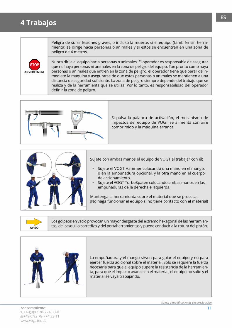
Si pulsa la palanca de activación, el mecanismo de impactos del equipo de VOGT se alimenta con aire comprimido y la máquina arranca.
Peligro de sufrir lesiones graves, o incluso la muerte, si el equipo (también sin herra-mienta) se dirige hacia personas o animales y si estos se encuentran en una zona de peligro de 4 metros.
Nunca dirija el equipo hacia personas o animales. El operador es responsable de asegurar que no haya personas ni animales en la zona de peligro del equipo. Tan pronto como haya personas o animales que entren en la zona de peligro, el operador tiene que parar de in-mediato la máquina y asegurarse de que estas personas o animales se mantienen a una distancia de seguridad suficiente. La zona de peligro siempre depende del trabajo que se realiza y de la herramienta que se utiliza. Por lo tanto, es responsabilidad del operador definir la zona de peligro.
ADVERTENCIA

12Sujeto a modificaciones sin previo aviso
Asesoramiento:+49(0)92 78-774 33-0
+49(0)92 78-774 33-11www.vogt-tec.de
ES
Después de 4 horas como máximo, compruebe si el portaherramientas está provisto de una capa de aceite. Si no es así, añada unas gotas de aceite especial de VOGT (Z 500) en la manguera de conexión. Recomendamos continuar la operación junto con el engrasador de líneas de precisión de VOGT. Si ya está utilizando este engrasador, compruebe su nivel de aceite y el ajuste (véase la página 8). Es recomendable engrasar el extremo hexagonal si las fuerzas de presión son muy intensas.Una gran cantidad de aceite también amortigua la fuerza del impacto. Se forman gotas en la palanca de activación o en el portaherramientas. En estos casos, debe reducirse la cantidad de aceite del engrasador (véase la página 8) y limpiar el equipo si es necesario (véase la página 13). Una cantidad muy pequeña de aceite provoca daños en el equipo y en la herramienta. Controlar el suministro de aceite y rellenar en caso necesario, o ajustar el engrasador (véase la página 8).
Si el equipo, la herramienta o los accesorios presentan daños, solicite a un taller especializado o al fabricante su reparación o sustitución. Encontrará cualquier número de pedido que necesite en la lista de herramientas que se detalla en el capítulo 11 o en la lista de piezas de repuesto del capítulo 12.
Peligro de lesión
Peligro de caída si por un cambio inesperado de peso el mango o la herramienta se rompen.
No hacer mucha palanca.ATENCIÓN
Peligros debidos a vibraciones.
La exposición prolongada del cuerpo humano a las vibraciones puede producir daños físicos permanentes como son el entumecimiento o los daños en el sistema nervioso.
Tenga en cuenta los tiempos de encendido permitidos y, en caso necesario, lleve guantes de protección a prueba de vibraciones que estén homologados.
ATENCIÓN
Nunca bloquee la palanca de activación con bridas de plástico, cinta adhesiva u otros medios.
Peligro de lesiones graves, la muerte o de daños en el equipo o la herramienta si la palanca de activación se bloquea de forma permanente.
ADVERTENCIA
Se puede hacer palanca de forma moderada. Hacer palanca con demasiada fuerza puede romper el mango o la herramienta.
Al soltar la palanca de activación, el suministro de aire comprimido se interrumpe. La máquina se detiene con un breve tiempo de marcha por inercia (depen-diendo de la longitud del dispositivo).
13Sujeto a modificaciones sin previo aviso
Asesoramiento: +49(0)92 78-774 33-0 +49(0)92 78-774 33-11www.vogt-tec.de
ES
5 Mantenimiento y cuidado
4.1 Pausas y fin del trabajo
Interrumpa el suministro de aire que va desde la manguera de aire comprimido al equipo.
Si se detiene el trabajo por poco tiempo: • Coloque de forma segura el equipo a un lado. • Si hay herramientas cortantes o puntiagudas colocadas, asegúrese de que nadie pueda herirse.
Si se finaliza el trabajo:• Interrumpa el suministro de aire comprimido.• Extraiga la herramienta de la máquina. • Compruebe si el portaherramientas está provisto de una capa de aceite.
Si no es así, añada unas gotas de aceite especial de VOGT (Z 500) en la manguera de conexión y opere el equipo sin herramienta durante unos 10 segundos.
• Limpie el equipo de aire comprimido de VOGT, las herramientas, la manguera y los accesorios con un paño limpio y seco o empapado en aceite.
• Almacene, en la medida de lo posible, los equipos de aire comprimido de VOGT en el maletín de transporte metálico previsto para este fin.
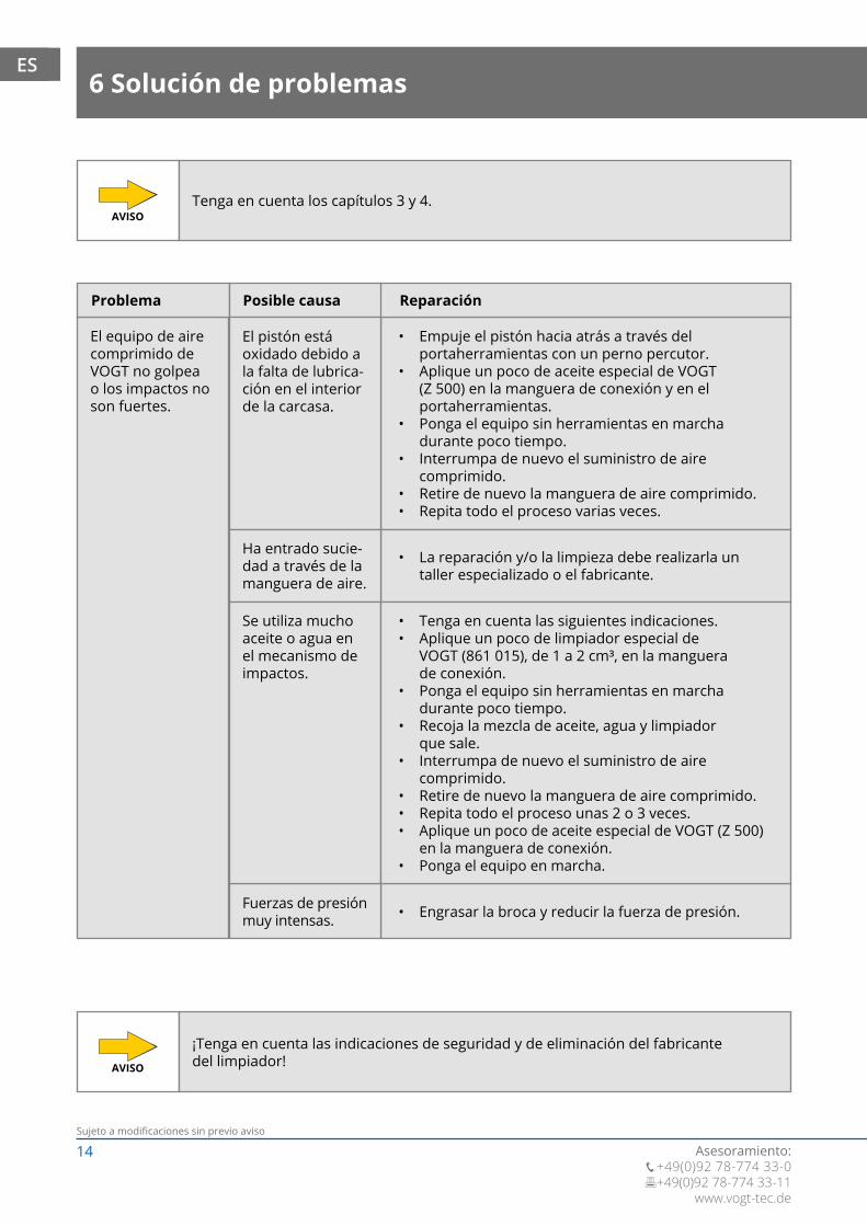
Al pulsar la tecla A, el acoplamiento se desbloquea una vez fina-lice la ventilación completa y automática del sistema de acuerdo con la norma DIN ISO 4414.
Después de esta ventilación, retire la manguera.
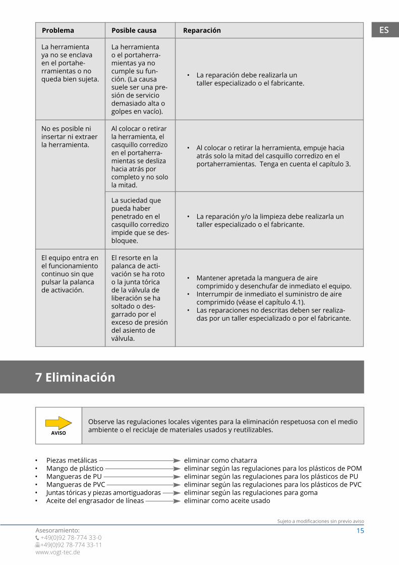
Si mantiene un suministro de aceite periódico del equipo, este no requiere mantenimiento.
14Sujeto a modificaciones sin previo aviso
Asesoramiento:+49(0)92 78-774 33-0
+49(0)92 78-774 33-11www.vogt-tec.de
ES6 Solución de problemas
Tenga en cuenta los capítulos 3 y 4.AVISO
¡Tenga en cuenta las indicaciones de seguridad y de eliminación del fabricante del limpiador!AVISO
• Empuje el pistón hacia atrás a través del portaherramientas con un perno percutor.
• Aplique un poco de aceite especial de VOGT (Z 500) en la manguera de conexión y en el portaherramientas.
• Ponga el equipo sin herramientas en marcha durante poco tiempo.
• Interrumpa de nuevo el suministro de aire comprimido.
• Retire de nuevo la manguera de aire comprimido.• Repita todo el proceso varias veces.
El equipo de aire comprimido de VOGT no golpea o los impactos no son fuertes.
El pistón está oxidado debido a la falta de lubrica-ción en el interior de la carcasa.
• La reparación y/o la limpieza debe realizarla un taller especializado o el fabricante.
Ha entrado sucie-dad a través de la manguera de aire.
• Engrasar la broca y reducir la fuerza de presión.Fuerzas de presión muy intensas.
Problema Posible causa
Se utiliza mucho aceite o agua en el mecanismo de impactos.
• Tenga en cuenta las siguientes indicaciones.• Aplique un poco de limpiador especial de
VOGT (861 015), de 1 a 2 cm³, en la manguera de conexión.
• Ponga el equipo sin herramientas en marcha durante poco tiempo.
• Recoja la mezcla de aceite, agua y limpiador que sale.
• Interrumpa de nuevo el suministro de aire comprimido.
• Retire de nuevo la manguera de aire comprimido.• Repita todo el proceso unas 2 o 3 veces. • Aplique un poco de aceite especial de VOGT (Z 500)
en la manguera de conexión. • Ponga el equipo en marcha.
Reparación
15Sujeto a modificaciones sin previo aviso
Asesoramiento: +49(0)92 78-774 33-0 +49(0)92 78-774 33-11www.vogt-tec.de
ES
• La reparación debe realizarla un taller especializado o el fabricante.
La herramienta ya no se enclava en el portahe-rramientas o no queda bien sujeta.
La herramienta o el portaherra-mientas ya no cumple su fun-ción. (La causa suele ser una pre-sión de servicio demasiado alta o golpes en vacío).
• Al colocar o retirar la herramienta, empuje hacia atrás solo la mitad del casquillo corredizo en el portaherramientas. Tenga en cuenta el capítulo 3.
• La reparación y/o la limpieza debe realizarla un taller especializado o el fabricante.
No es posible ni insertar ni extraer la herramienta.
Al colocar o retirar la herramienta, el casquillo corredizo en el portaherra-mientas se desliza hacia atrás por completo y no solo la mitad.
La suciedad que pueda haber penetrado en el casquillo corredizo impide que se des-bloquee.
• Mantener apretada la manguera de aire comprimido y desenchufar de inmediato el equipo.
• Interrumpir de inmediato el suministro de aire comprimido (véase el capítulo 4.1).
• Las reparaciones no descritas deben ser realiza-das por un taller especializado o por el fabricante.
El resorte en la palanca de acti-vación se ha roto o la junta tórica de la válvula de liberación se ha soltado o des-garrado por el exceso de presión del asiento de válvula.
El equipo entra en el funcionamiento continuo sin que pulsar la palanca de activación.
Problema Posible causa Reparación
7 Eliminación
• Piezas metálicas• Mango de plástico• Mangueras de PU• Mangueras de PVC• Juntas tóricas y piezas amortiguadoras• Aceite del engrasador de líneas
eliminar como chatarraeliminar según las regulaciones para los plásticos de POMeliminar según las regulaciones para los plásticos de PUeliminar según las regulaciones para los plásticos de PVCeliminar según las regulaciones para gomaeliminar como aceite usado
Observe las regulaciones locales vigentes para la eliminación respetuosa con el medio ambiente o el reciclaje de materiales usados y reutilizables.AVISO
16Sujeto a modificaciones sin previo aviso
Asesoramiento:+49(0)92 78-774 33-0
+49(0)92 78-774 33-11www.vogt-tec.de
ES8 Datos técnicos
• Disponibles dispositivos con longitudes especiales de 34 cm a 600 cm. Los datos técnicos de estos equipos especiales no se muestran en este manual.
• La versión con mango Delta es aproximadamente 1 kg más pesada que la versión con mango convencional.
AVISO
Valores declarados de emisión sonora de dos cifras conforme a EN 15744 y EN ISO 4871Valor total de la vibración conforme a EN 28927
Declaración de ruidos conforme a la Directiva 2000/14/CE
VH 10-30 Y de nuevo... otra novedad de la casa VOGT
La casa VOGT tiene el honor de anunciar la inminente salida al mercado del nuevo multitalento con amortiguación de vibraciones.
Encontrará más información en: www.vogt-tec.de
El fabricante / tipo (1) y número de serie / año de construcción (2) están gravados en el equipo.
1 2
facebook.com/vogtbaugeraete
youtube.com/vogtbaugeraete

17Sujeto a modificaciones sin previo aviso
Asesoramiento: +49(0)92 78-774 33-0 +49(0)92 78-774 33-11www.vogt-tec.de
ES
Longitud total
Peso
Mango Delta
Medio de servicio
Presión de servicio
Tipo VH 25-70 VH 30-70 VH 25-90 VH 30-90 VH 25-110 VH 30-110 VH 25-130 VH 30-130
Aire
3,0 - 6,0 bares (44 - 87 psi)
Consumo de aire 190 l/min (6.7 cfm) con 6.0 bar (87 psi)
Cantidad de impactos
Nivel de potencia acústica ponderado LWA (EN 15744 / EN ISO 4871)
Nivel de presión acústica de emisión ponderado Lpa (EN 15744 / EN ISO 4871)
Portaherramientas
Diámetro interior de la manguera
3200/min
105 dB (incertidumbre: +3 dB)
94 dB (incertidumbre: +3 dB)
14 mm, hexagonal
9 mm mín. (3/8”)
Valor total de la vibración h
Incertidumbre K
VH 25: 13,1 m/s2 / VH 30: 6,5 m/s2
VH 25: 1,5 m/s2 / VH 30: 1,1 m/s2 Medición de carga (EN ISO 28927)
Longitud total
Peso
Mango Delta
Medio de servicio
Presión de servicio
Tipo VH 50-70 VH 60-70 VH 50-90 VH 60-90 VH 50-110 VH 60-110 VH 50-130 VH 60-130
Aire
3,0 - 6,0 bares (44 - 87 psi)
70 cm(27.6”)
70 cm(27.6”)
90 cm(35.4”)
90 cm(35.4”)
110 cm(43.3”)
110 cm(43.3”)
130 cm(51.2”)
130 cm(51.2”)
3,2 kg(7.1 lb)
4,0 kg(8.8 lb)
3,5 kg(7.7 lb)
4,3 kg(9.5 lb)
3,8 kg(8.4 lb)
4,6 kg(10.1 lb)
4,1 kg(9.0 lb)
4,9 kg(10.8 lb)
4,2 kg(9.3 lb)
5,0 kg(11.0 lb)
4,5 kg(9.9 lb)
5,3 kg(11.7 lb)
4,8 kg(10.6 lb)
5,6 kg(12.3 lb)
5,1 kg(11.2 lb)
5,9 kg(13.0 lb)
70 cm(27.6”)
70 cm(27.6”)
90 cm(35.4”)
90 cm(35.4”)
110 cm(43.3”)
110 cm(43.3”)
130 cm(51.2”)
130 cm(51.2”)
4,4 kg(9.7 lb)
5,5 kg(12.1 lb)
4,8 kg(10.6 lb)
5,9 kg(13.0 lb)
5,2 kg(11.5 lb)
6,3 kg(13.9 lb)
5,6 kg(12.3 lb)
6,7 kg(14.8 lb)
5,4 kg(11.9 lb)
6,5 kg(14.3 lb)
5,8 kg(12.8 lb)
6,9 kg(15.2 lb)
6,2 kg(13.7 lb)
7,3 kg(16.1 lb)
6,6 kg(14.6 lb)
7,7 kg(17.0 lb)
Consumo de aire 255 l/min (9.2 cfm) con 6.0 bar (87 psi)
Cantidad de impactos
Nivel de potencia acústica ponderado LWA (EN 15744 / EN ISO 4871)
Nivel de presión acústica de emisión ponderado Lpa (EN 15744 / EN ISO 4871)
Diámetro interior de la manguera
Portaherramientas
1960/min
105 dB (incertidumbre: +3 dB)
94 dB (incertidumbre: +3 dB)
9 mm mín. (3/8”)
14 mm, hexagonal
Valor total de la vibración h
Incertidumbre K
VH 50: 21,0 m/s2 / VH 60: 4,7 m/s2
VH 50: 2,6 m/s2 / VH 60: 1,0 m/s2 Medición de carga (EN ISO 28927)
18Sujeto a modificaciones sin previo aviso
Asesoramiento:+49(0)92 78-774 33-0
+49(0)92 78-774 33-11www.vogt-tec.de
ES
Longitud total
Peso
Mango Delta
Medio de servicio
Presión de servicio
Consumo de aire
Cantidad de impactos
Nivel de potencia acústica ponderado LWA (EN 15744 / EN ISO 4871)
Nivel de presión acústica de emisión ponderado Lpa (EN 15744 / EN ISO 4871)
Diámetro interior de la manguera
Portaherramientas
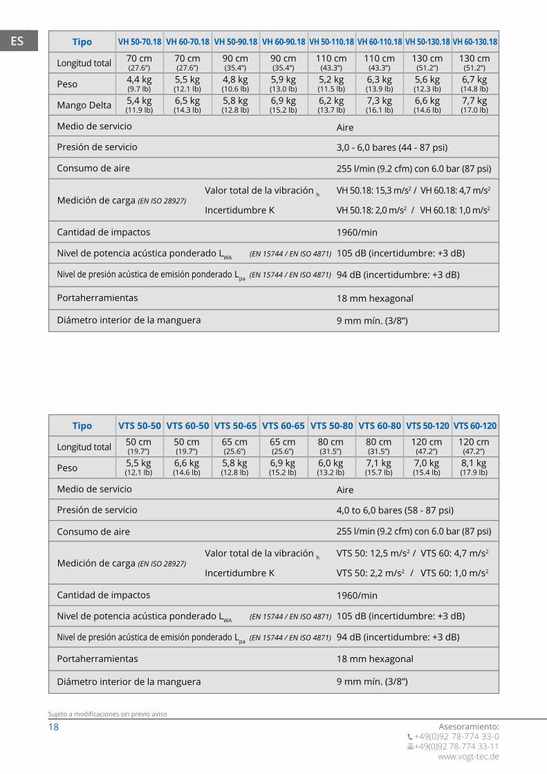
Tipo VH 50-70.18 VH 60-70.18 VH 50-90.18 VH 60-90.18 VH 50-110.18 VH 50-130.18VH 60-110.18 VH 60-130.18
Aire
3,0 - 6,0 bares (44 - 87 psi)
1960/min
105 dB (incertidumbre: +3 dB)
94 dB (incertidumbre: +3 dB)
255 l/min (9.2 cfm) con 6.0 bar (87 psi)
9 mm mín. (3/8”)
18 mm hexagonal
Valor total de la vibración h
Incertidumbre K
VH 50.18: 15,3 m/s2 / VH 60.18: 4,7 m/s2
VH 50.18: 2,0 m/s2 / VH 60.18: 1,0 m/s2 Medición de carga (EN ISO 28927)
Longitud total
Peso
Medio de servicio
Presión de servicio
Consumo de aire
Cantidad de impactos
Nivel de potencia acústica ponderado LWA (EN 15744 / EN ISO 4871)
Nivel de presión acústica de emisión ponderado Lpa (EN 15744 / EN ISO 4871)
Diámetro interior de la manguera
Portaherramientas
Tipo VTS 50-50 VTS 60-50 VTS 50-65 VTS 60-65 VTS 50-80 VTS 60-80 VTS 50-120 VTS 60-120
Aire
4,0 to 6,0 bares (58 - 87 psi)
1960/min
105 dB (incertidumbre: +3 dB)
94 dB (incertidumbre: +3 dB)
255 l/min (9.2 cfm) con 6.0 bar (87 psi)
9 mm mín. (3/8”)
18 mm hexagonal
Valor total de la vibración h
Incertidumbre K
VTS 50: 12,5 m/s2 / VTS 60: 4,7 m/s2
VTS 50: 2,2 m/s2 / VTS 60: 1,0 m/s2 Medición de carga (EN ISO 28927)
50 cm(19.7”)
50 cm(19.7”)
65 cm(25.6”)
65 cm(25.6”)
80 cm(31.5”)
80 cm(31.5”)
120 cm(47.2”)
120 cm(47.2”)
5,5 kg(12.1 lb)
6,6 kg(14.6 lb)
5,8 kg(12.8 lb)
6,9 kg(15.2 lb)
6,0 kg(13.2 lb)
7,1 kg(15.7 lb)
7,0 kg(15.4 lb)
8,1 kg(17.9 lb)
70 cm(27.6”)
70 cm(27.6”)
90 cm(35.4”)
90 cm(35.4”)
110 cm(43.3”)
110 cm(43.3”)
130 cm(51.2”)
130 cm(51.2”)
4,4 kg(9.7 lb)
5,5 kg(12.1 lb)
4,8 kg(10.6 lb)
5,9 kg(13.0 lb)
5,2 kg(11.5 lb)
6,3 kg(13.9 lb)
5,6 kg(12.3 lb)
6,7 kg(14.8 lb)
5,4 kg(11.9 lb)
6,5 kg(14.3 lb)
5,8 kg(12.8 lb)
6,9 kg(15.2 lb)
6,2 kg(13.7 lb)
7,3 kg(16.1 lb)
6,6 kg(14.6 lb)
7,7 kg(17.0 lb)

19Sujeto a modificaciones sin previo aviso
Asesoramiento: +49(0)92 78-774 33-0 +49(0)92 78-774 33-11www.vogt-tec.de
ES
Principio básico: Cuanto menor es la resistencia del material, menor es la presión de servicio. La presión de servicio es demasiado alta si la herramienta se separa del material sin control. La presión excesiva aumenta las vibraciones, reduce el rendimiento de trabajo y provoca daños en el equipo.
AVISO
Contenido utilizable
Engrasador de líneas de precisión de VOGT Z 300 / Z 300 S
Presión máx. de servicio
Presión máx. de funcionamiento
20 ml
16 bar (232 psi)
-10°C to +50°C
La presión de servicio debe adaptarse al material y al subsuelo.Recomendaciones basadas en la experiencia:
Presión de servicio para el procesamiento de diferentes materiales con VOGT Turbo Spaten VTS 50, VTS 60
Excavado
Cincelado
Presión máxima de servicio
Compactado
6,0 bar (87 psi)
5,0 to 6,0 bar (72 - 87 psi)
6,0 bar (87 psi)
6,0 bar (87 psi)
La presión de servicio debe adaptarse al material y al subsuelo.Recomendaciones basadas en la experiencia:
Presión de servicio para el procesamiento de diferentes materiales con VOGT Hammer / VOGT Hammer Delta VH 10, VH 25, VH 30, VH 50, VH 50.18, VH 60, VH 60.18
Saneamiento de juntas
Revoque de cal yeso
Parqué, laminado
Azulejos pegados
Compactado
Pavimentos, revestimientos
Revoque de cal y cemento
Revoque fino, revoque friccionado
Azulejos en lecho de mortero
Cincelado
Excavado
Presión máxima de servicio
3,0 to 5,0 bar (44 - 72 psi)
5,0 to 6,0 bar (72 - 87 psi)
4,0 to 6,0 bar (58 - 87 psi)
6,0 bar (87 psi)
5,0 to 6,0 bar (72 - 87 psi)
5,0 to 6,0 bar (72 - 87 psi)
5,0 bar (72 psi)
6,0 bar (87 psi)
6,0 bar (87 psi)
5,0 to 6,0 bar (72 - 87 psi)
6,0 bar (87 psi)
6,0 bar (87 psi)
20Subject to change without notice
Contact: +49(0)92 78-774 33-0 +49(0)92 78-774 33-11
www.vogt-tec.de
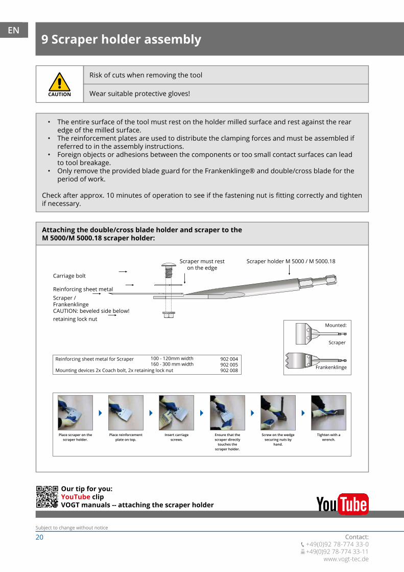
Attaching the double/cross blade holder and scraper to theM 5000/M 5000.18 scraper holder:
Carriage bolt
Scraper must reston the edge
Scraper holder M 5000 / M 5000.18
Fertig montiert:
Schaber
Reinforcing sheet metal
retaining lock nut
Reinforcing sheet metal for Scraper
Mounting devices 2x Coach bolt, 2x retaining lock nut
100 - 120mm width160 - 300 mm width
902 004902 005902 008
Scraper /FrankenklingeCAUTION: beveled side below!
Place scraper on thescraper holder.
Place reinforcementplate on top.
Insert carriagescrews.
Ensure that thescraper directly
touches thescraper holder.
Screw on the wedgesecuring nuts by
hand.
Tighten with awrench.
Mounted:
Frankenklinge
Scraper
Our tip for you:YouTube clipVOGT manuals -- attaching the scraper holder
• The entire surface of the tool must rest on the holder milled surface and rest against the rear edge of the milled surface.
• The reinforcement plates are used to distribute the clamping forces and must be assembled if referred to in the assembly instructions.
• Foreign objects or adhesions between the components or too small contact surfaces can lead to tool breakage.
• Only remove the provided blade guard for the Frankenklinge® and double/cross blade for the period of work.
Check after approx. 10 minutes of operation to see if the fastening nut is fitting correctly and tighten if necessary.
Risk of cuts when removing the tool
Wear suitable protective gloves!CAUTION
9 Scraper holder assemblyEN
21Subject to change without notice
Contact: +49(0)92 78-774 33-0 +49(0)92 78-774 33-11www.vogt-tec.de
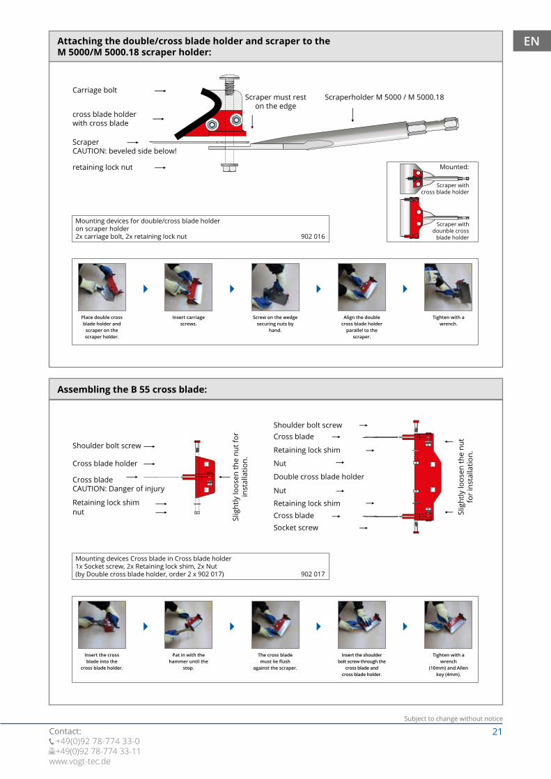
Attaching the double/cross blade holder and scraper to theM 5000/M 5000.18 scraper holder:
Carriage boltScraper must rest
on the edgeScraperholder M 5000 / M 5000.18
cross blade holderwith cross blade
retaining lock nut
Mounting devices for double/cross blade holderon scraper holder2x carriage bolt, 2x retaining lock nut
902 004902 005902 016
ScraperCAUTION: beveled side below!
Mounted:
Scraper withcross blade holder
Scraper withdounble cross
blade holder
Place double crossblade holder and
scraper on thescraper holder.
Insert carriagescrews.
Screw on the wedgesecuring nuts by
hand.
Align the doublecross blade holder
parallel to the scraper.
Tighten with awrench.
Assembling the B 55 cross blade:
Slig
htly
loos
en th
e nu
t for
inst
alla
tion.
Slig
htly
loos
en th
e nu
t fo
r in
stal
latio
n.
Mounting devices Cross blade in Cross blade holder1x Socket screw, 2x Retaining lock shim, 2x Nut(by Double cross blade holder, order 2 x 902 017)
902 004902 005902 017
Shoulder bolt screw
Cross blade holder
Retaining lock shimnut
Cross bladeCAUTION: Danger of injury
Insert the crossblade into the
cross blade holder.
Pat in with thehammer until the
stop.
The cross blademust lie flush
against the scraper.
Insert the shoulder bolt screw through the
cross blade andcross blade holder.
Tighten with a wrench
(10mm) and Allenkey (4mm).
Shoulder bolt screw
Socket screw
Cross blade
Cross blade
Nut
Double cross blade holder
Nut
Retaining lock shim
Retaining lock shim
EN

22Subject to change without notice
Contact: +49(0)92 78-774 33-0 +49(0)92 78-774 33-11
www.vogt-tec.de
Attaching the parquet wedge and Frankenklinge® blades to theM 5000/M 5000.18 scraper holder:
Parquet wedge
Retaining locknut Scraper holder M 5000 / M 5000.18Scraper must rest
on the edge
Frankenklinge
Holding plate with pressed-in screws
Mounting devices 1x Holding plate, 1x Reinforcing sheet metal, 2x Retaining lock nut
902 060
Mounted:
Parquet wedgewith Frankenklinge
Insert the holdingplate from below
through the scraperholder.
Push the Fran-kenklinge®
blade on to thethreaded pins.
Push the parquetwedge on to thethreaded pins.
Screw on the wedgesecuring nuts by
hand.
Tighten with awrench.
Attaching the devlection device and scrapers to theM 5000/M 500.18 scraper holder:
Deflection device Scraper mustrest on the edge
Scraper holder M 5000 / M 5000.18Reinforcing sheet
meta
Retaining locknut
Fertig montiert:
Schaber
ScraperCAUTION: beveled side below!
Holding plate with pressed-in screws
Insert the holdingplate from below
through the scraperholder.
Push the scraperon to the holding
plate.
Push the deviatordevice on to the
holding plate.
Push the reinforce-ment plate (black plate) on to the threaded plate.
Screw on the Retaining
lock nut by hand.
Tighten with awrench.
Mounted:
Scraper withDeflection device
Mounting devices 1x Holding plate, 1x Reinforcing sheet metal, 2x Retaining lock nut
902 020
EN
23Subject to change without notice
Contact: +49(0)92 78-774 33-0 +49(0)92 78-774 33-11www.vogt-tec.de
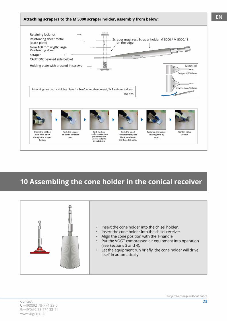
Attaching scrapers to the M 5000 scraper holder, assembly from below:
Retaining lock nut
ScraperCAUTION: beveled side below!
Reinforcing sheet metal(black plate)from 160 mm wigth: largeReinforcing sheet
Scraper must reston the edge
Scraper holder M 5000 / M 5000.18
Fertig montiert:
Schaber
Holding plate with pressed-in screws
Insert the holdingplate from below
through the scraperholder.
Push the scraperon to the threaded
pins.
Push the largereinforcement plate
(160 scraper and above) on to the threaded pins.
Push the smallreinforcement plate(black plate) on to
the threaded plate.
Screw on the wedgesecuring nuts by
hand.
Tighten with awrench.
Fertig montiert:
Schaber mit Umlenkvorrichtung
Mounting devices 1x Holding plate, 1x Reinforcing sheet metal, 2x Retaining lock nut
902 020
EN
Mounted:
Scraper till 160 mm
Scraper from 160 mm
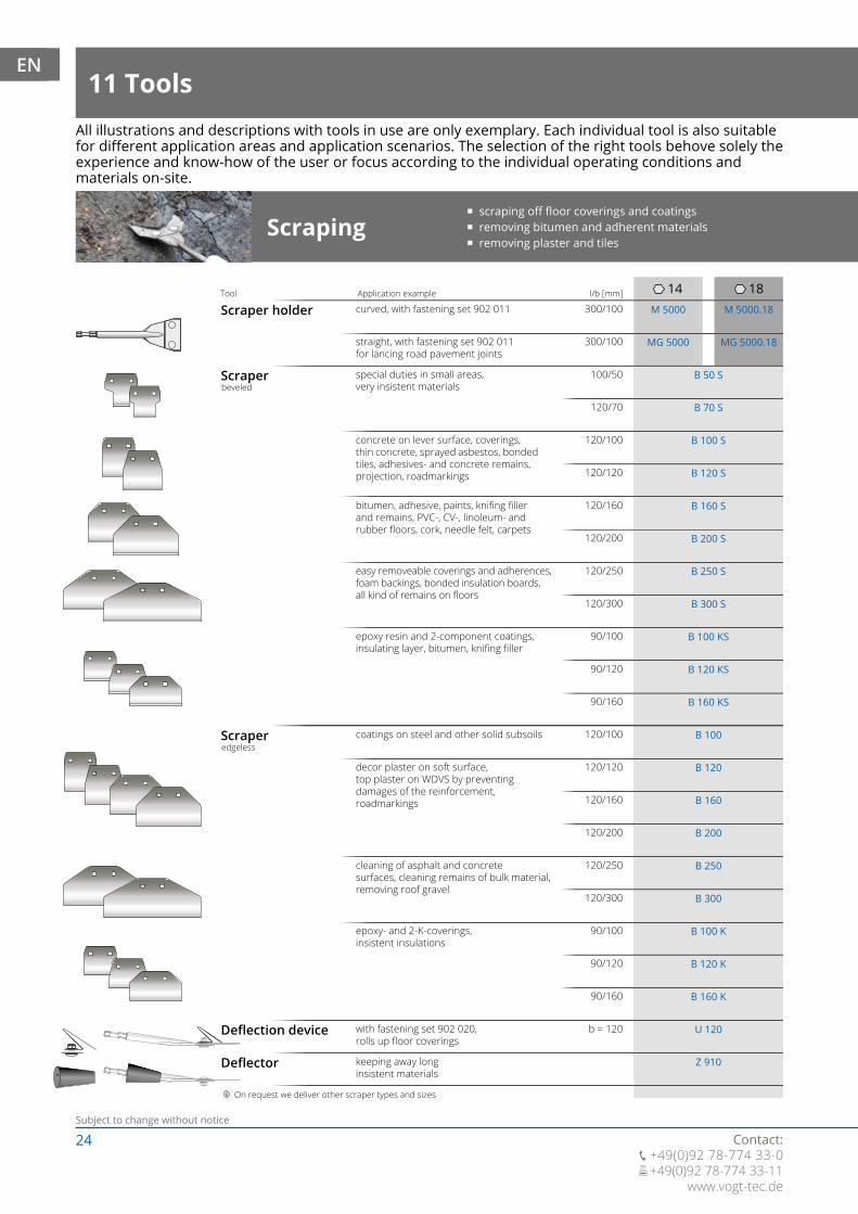
• Insert the cone holder into the chisel holder.• Insert the cone holder into the chisel receiver.• Align the cone position with the T-handle• Put the VOGT compressed air equipment into operation
(see Sections 3 and 4).• Let the equipment run briefly, the cone holder will drive
itself in automatically
10 Assembling the cone holder in the conical receiver
24Subject to change without notice
Contact: +49(0)92 78-774 33-0 +49(0)92 78-774 33-11
www.vogt-tec.de
14 18l/b [mm]
300/100
100/50
120/100
120/100
b = 120
120/160
120/160
120/250
120/250
90/100
90/100
120/120
120/120
120/200
120/200
120/300
120/300
90/120
90/120
90/160
90/160
120/70
M 5000
B 50 S
B 100 S
B 100
U 120
Z 910
B 160 S
B 160
B 250 S
B 250
B 100 KS
B 100 K
B 120 S
B 120
B 200 S
B 200
B 300 S
B 300
B 120 KS
B 120 K
B 160 KS
B 160 K
B 70 S
MG 5000
M 5000.18
MG 5000.18300/100
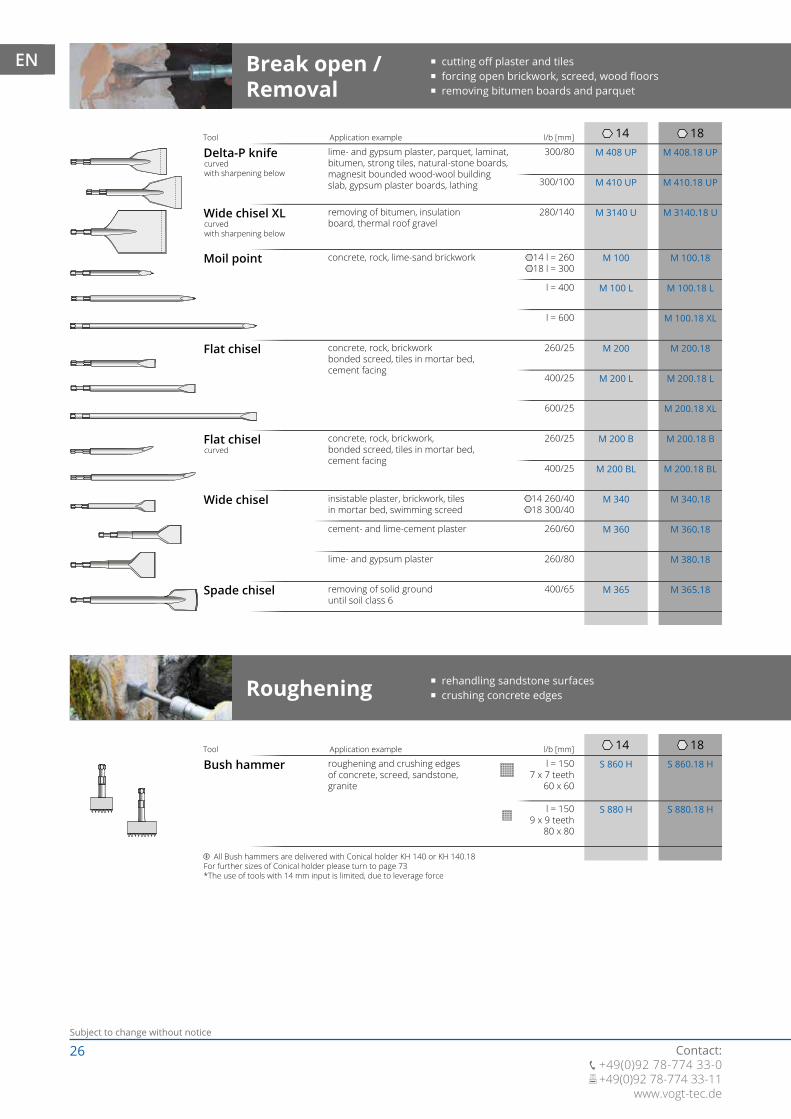
All illustrations and descriptions with tools in use are only exemplary. Each individual tool is also suitablefor different application areas and application scenarios. The selection of the right tools behove solely theexperience and know-how of the user or focus according to the individual operating conditions and materials on-site.
Scraping � scraping off floor coverings and coatings � removing bitumen and adherent materials � removing plaster and tiles
Scraper holder
Scraper
Scraper
Deflection device
Deflector
curved, with fastening set 902 011
special duties in small areas,very insistent materials
concrete on lever surface, coverings,thin concrete, sprayed asbestos, bondedtiles, adhesives- and concrete remains,projection, roadmarkings
coatings on steel and other solid subsoils
with fastening set 902 020,rolls up floor coverings
keeping away longinsistent materials
bitumen, adhesive, paints, knifing fillerand remains, PVC-, CV-, linoleum- andrubber floors, cork, needle felt, carpets
decor plaster on soft surface,top plaster on WDVS by preventingdamages of the reinforcement,roadmarkings
easy removeable coverings and adherences,foam backings, bonded insulation boards,all kind of remains on floors
cleaning of asphalt and concretesurfaces, cleaning remains of bulk material,removing roof gravel
epoxy resin and 2-component coatings,insulating layer, bitumen, knifing filler
epoxy- and 2-K-coverings,insistent insulations
Application example
On request we deliver other scraper types and sizes
Tool
beveled
edgeless
straight, with fastening set 902 011for lancing road pavement joints
11 ToolsEN

25Subject to change without notice
Contact: +49(0)92 78-774 33-0 +49(0)92 78-774 33-11www.vogt-tec.de
Schneiden
l/b [mm]
150/120
150/200
200/160
b = 90
b = 120
b = 160
b = 200
200/120
B 200 F
902 005
B 160 F
902 004
B 120 F
902 008
B 160 LF
902 020
PK 90
902 016
H 120 B
902 060
H 100 B
861 004
H 160 B
H 200 B
B 55
H 425 H H 425.18 H
B 25
B 120 LF
902 011
150/160
� Bodenbeläge und Beschichtungen abschaben � Bitumen und Anhaftungen abtragen � Putze und Fliesen entfernen
225/160
225/120 B 120 T
B 160 T
Frankenklinge
Parquet wedge
Cross blade holderwith blade
cutting PU-elastic adhesive parquetand laminate floors, ship´s decks andfacade claddings the more stiff the adhesive, the
smaller the scraper should be
cutting PU-elastic adhesive parquetand laminate floors, boot decks andfacade panellings the more stiff the adhesive, the
small the scraper should be
Cross blade for cutting off softflooring in all width
Application example Tool
beveled on both sidesfor panel widthup to 100 mm
for panel widthfrom 100 mmup to 150 mm
Cutting � removing PU-elastic adhesive parquet � cutting and removing syncronous
Trapezoid blade split the 2-layered polyester fabricKiesel Okalift SuperChange With the new system, wall coverings and
floor coverings can be exchanged carefullyand without big effort
with fastening set 902 060, reducesthe frictional resistance of PU-adhesives
sharply whetted
Double-cross bladeholder withblades
Cross blade
Cutting-devicewith cutting blade
readily soluble coverings and adherentmaterials, foam backings carpet, gluedinsulating panels, dirt remains at floor
beveled on both sidesBlade for cross blade holder H 100 B / Double-cross blade holder H 120 B, H 160 B, H 200 B
Pre-cutting of soft flooring, seals (1-2 lays)
Blade for cutting-device H 400 H / H 400.18 HCutting bladebeveled on both sides
Fastening set
Ring wrench
Accessories and attachments for Scraper holder
standard fastening set for Scraper holder
small reinforcing plate for Scrapersuntil 120 mm width
large reinforcing plate for Scrapersup to 160 mm width
standard fastening set with small and largereinforcing plate
fastening set below, to achieve an evenoperating angle
fastening set for Parquet wedge
fastening set for cross blade /double-cross blade
deep-offset, size 15-19for Scraper holder and Handle
EN
26Subject to change without notice
Contact: +49(0)92 78-774 33-0 +49(0)92 78-774 33-11
www.vogt-tec.de
14
14
18
18l/b [mm]
300/80
280/140
260/60
14 l = 260 18 l = 300
400/65
260/25
260/25
l = 400
400/25
400/25
14 260/40 18 300/40
300/100
S 860 H
S 880 H
S 860.18 H
S 880.18 H
M 408 UP M 408.18 UP
M 410 UP M 410.18 UP
M 3140 U M 3140.18 U
M 100 M 100.18
M 100 L M 100.18 L
M 200 M 200.18
M 200 L M 200.18 L
M 200 B M 200.18 B
M 200 BL M 200.18 BL
M 340 M 340.18
M 360 M 360.18
M 365 M 365.18
l = 600
600/25
M 100.18 XL
M 200.18 XL
260/80 M 380.18
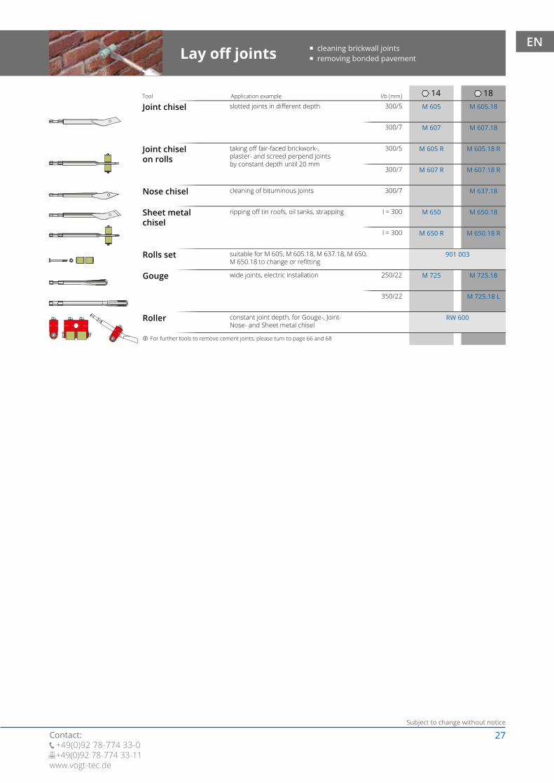
Break open /Removal
Delta-P knife lime- and gypsum plaster, parquet, laminat,bitumen, strong tiles, natural-stone boards,magnesit bounded wood-wool buildingslab, gypsum plaster boards, lathing
removing of bitumen, insulationboard, thermal roof gravel
concrete, rock, lime-sand brickwork
concrete, rock, brickworkbonded screed, tiles in mortar bed,cement facing
concrete, rock, brickwork,bonded screed, tiles in mortar bed,cement facing
Application example l/b [mm]Tool
� cutting off plaster and tiles � forcing open brickwork, screed, wood floors � removing bitumen boards and parquet
Wide chisel XL
Moil point
Flat chisel
curved with sharpening below
curvedwith sharpening below
Flat chiselcurved
Wide chisel
Spade chisel
cement- and lime-cement plaster
removing of solid grounduntil soil class 6
lime- and gypsum plaster
insistable plaster, brickwork, tilesin mortar bed, swimming screed
Bush hammer
Roughening
roughening and crushing edgesof concrete, screed, sandstone,granite
Application example Tool
l = 1507 x 7 teeth
60 x 60
l = 1509 x 9 teeth
80 x 80
� rehandling sandstone surfaces � crushing concrete edges
All Bush hammers are delivered with Conical holder KH 140 or KH 140.18For further sizes of Conical holder please turn to page 73*The use of tools with 14 mm input is limited, due to leverage force
EN
27Subject to change without notice
Contact: +49(0)92 78-774 33-0 +49(0)92 78-774 33-11www.vogt-tec.de
14 18300/5
300/5
300/7
l = 300
350/22
l = 300
250/22
300/7
M 605
M 607
M 605.18
M 607.18300/7
M 605 R M 605.18 R
M 607 R M 607.18 R
M 637.18
M 650 M 650.18
M 650 R M 650.18 R
M 200 M 200.18192,- 202,-M 725 M 725.18
M 725.18 L
901 003
RW 600
Joint chisel
Joint chiselon rolls
slotted joints in different depth
taking off fair-faced brickwork-,plaster- and screed perpend jointsby constant depth until 20 mm
cleaning of bituminous joints
ripping off tin roofs, oil tanks, strapping
suitable for M 605, M 605.18, M 637.18, M 650,M 650.18 to change or refitting
wide joints, electric installation
Application example l/b [mm]Tool
Lay off joints � cleaning brickwall joints � removing bonded pavement
Nose chisel
Sheet metalchisel
Rolls set
Gouge
Roller constant joint depth, for Gouge-, Joint-Nose- and Sheet metal chisel
For further tools to remove cement joints, please turn to page 66 and 68
EN
28Subject to change without notice
Contact: +49(0)92 78-774 33-0 +49(0)92 78-774 33-11
www.vogt-tec.de
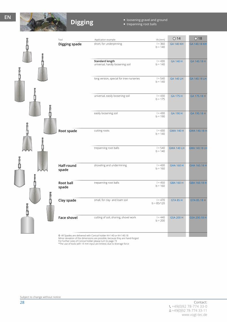
14 18l/b [mm]
l = 360b = 140
GA 140 KH GA 140.18 KH
l = 430b = 140
l = 430b = 175
l = 430b = 190
l = 430b = 140
l = 430b = 160
l = 450b = 160
l = 470b = 85/120
GA 140 H GA 140.18 H
GA 175 H GA 175.18 H
GA 190 H GA 190.18 H
GWA 140 H GWA 140.18 H
GHA 160 H GHA 160.18 H
GBA 160 H GBA 160.18 H
GTA 85 H GTA 85.18 H
l = 540b = 140
GA 140 LH GA 140.18 LH
GWA 140 LH GWA 140.18 LH
l = 440b = 200
GSA 200 H GSA 200.18 H
l = 540b = 140
Digging spade
Digging
Root spade
short, for underpinning
cutting roots
Application example Tool
� loosening gravel and ground � trepanning root balls
Half-roundspade
Root ballspade
Clay spade
Standard lengthuniversal, hardly loosening soil
universal, easily loosening soil
easily loosening soil
shoveling and undermining
trepanning root balls
small, for clay- and loam soil
All Spades are delivered with Conical holder KH 140 or KH 140.18Minor deviation of the dimensions are possible, because they are hand-forgedFor further sizes of Conical holder please turn to page 73*The use of tools with 14 mm input are limited, due to leverage force
long version, special for tree nurseries
trepanning root balls
Face shovel cutting of soil, shoring, shovel work
EN
29Subject to change without notice
Contact: +49(0)92 78-774 33-0 +49(0)92 78-774 33-11www.vogt-tec.de
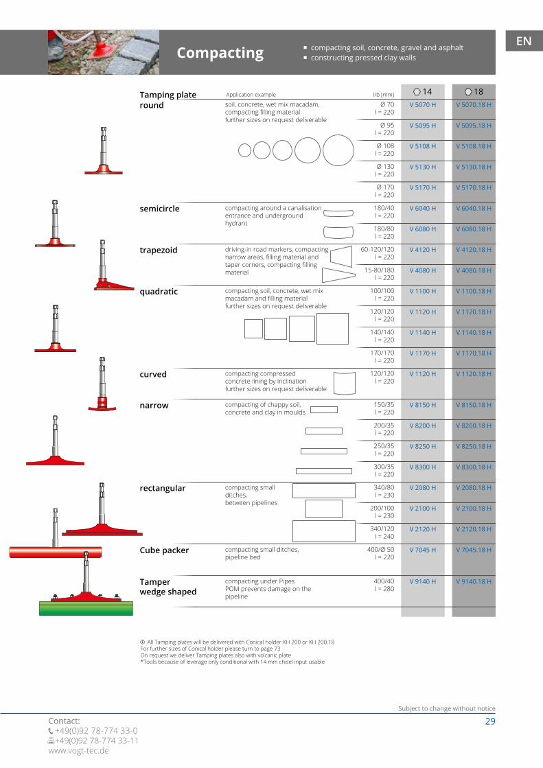
14 18l/b [mm]
Ø 70l = 220
V 5070 H
V 5095 H
V 5070.18 H
V 5095.18 HØ 95l = 220
Ø 108l = 220
Ø 130l = 220
Ø 170l = 220
180/40l = 220
180/80l = 220
60-120/120l = 220
15-80/180l = 220
100/100l = 220
120/120l = 220
140/140l = 220
170/170l = 220
V 5108 H V 5108.18 H
V 5130 H V 5130.18 H
V 5170 H V 5170.18 H
V 6040 H V 6040.18 H
V 6080 H V 6080.18 H
V 4120 H V 4120.18 H
V 4080 H V 4080.18 H
V 1100 H V 1100.18 H
V 1120 H V 1120.18 H
V 1140 H V 1140.18 H
V 1170 H V 1170.18 H
120/120l = 220
150/35l = 220
200/35l = 220
250/35l = 220
300/35l = 220
340/80l = 230
200/100l = 230
340/120l = 240
400/Ø 50l = 220
V 1120 H V 1120.18 H
V 8150 H V 8150.18 H
V 8200 H V 8200.18 H
V 8250 H V 8250.18 H
V 8300 H V 8300.18 H
V 2080 H V 2080.18 H
V 2100 H V 2100.18 H
V 2120 H V 2120.18 H
V 7045 H V 7045.18 H
All Tamping plates will be delivered with Conical holder KH 200 or KH 200.18For further sizes of Conical holder please turn to page 73On request we deliver Tamping plates also with volcanic plate*Tools because of leverage only conditional with 14 mm chisel input usable
Tamping platesoil, concrete, wet mix macadam,compacting filling materialfurther sizes on request deliverable
Application example
Compacting � compacting soil, concrete, gravel and asphalt � constructing pressed clay walls
round
semicircle
trapezoid
quadratic
compacting around a canalisationentrance and undergroundhydrant
driving-in road markers, compactingnarrow areas, filling material andtaper corners, compacting fillingmaterial
compacting soil, concrete, wet mixmacadam and filling materialfurther sizes on request deliverable
curved
narrow
rectangular
Cube packer
compacting compressedconcrete lining by inclinationfurther sizes on request deliverable
compacting of chappy soil,concrete and clay in moulds
compacting smallditches,between pipelines
compacting small ditches,pipeline bed
V 9140 H V 9140.18 H400/40l = 280
Tamperwedge shaped
compacting under PipesPOM prevents damage on thepipeline
EN
30Subject to change without notice
Contact: +49(0)92 78-774 33-0 +49(0)92 78-774 33-11
www.vogt-tec.de
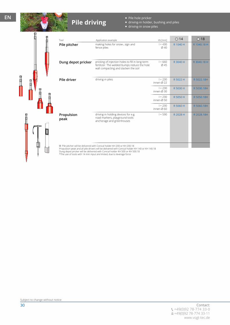
14 18l = 430
Ø 40R 1040 H R 1040.18 H
l = 660Ø 45
R 3040 H R 3040.18 H
R 5022 H
R 5030 H
R 5050 H
R 5060 H
R 5022.18H
R 5030.18H
R 5050.18H
R 5060.18H
R 2028 H R 2028.18Hl = 590
Pile pitcher
Pile driving
making holes for snow-, sign andfence piles
Application example l/b [mm]Tool
� Pile hole pricker � driving-in holder, bushing and piles � driving-in snow piles
pricking of injection holes to fill in long-termfertilizer. The welded bumps reduce the holewall compacting and slacken the soil
driving-in piles
Dung depot pricker
Pile driver
Propulsionpeak
driving-in holding devices for e.g.road markers, playground toolsanchorage and greenhouses
Pile pitcher will be delivered with Conical holder KH 200 or KH 200.18Propulsion peak and all pile drivers will be delivered with Conical holder KH 140 or KH 140.18Dung depot pricker will be delivered with Conical holder KH 500 or KH 500.18*The use of tools with 14 mm input are limited, due to leverage force
l = 230innen-Ø 22
l = 230innen-Ø 30
l = 230innen-Ø 50
l = 230innen-Ø 60
EN
31Subject to change without notice
Contact: +49(0)92 78-774 33-0 +49(0)92 78-774 33-11www.vogt-tec.de
14
14
18
18l/b [mm]
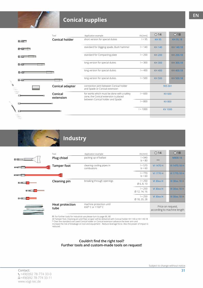
l = 95
l = 570b = 60
KH 95
VI 1470 H
KH 95.18
VI 1470.18 H
l = 140
l = 770b = 60
KH 140
VI 1770 H
KH 140.18
VI 1770.18 H
l = 200
l = 250Ø 6, 8, 10
KH 200
VI 30xx H
KH 200.18
VI 30xx.18 H
l = 300
l = 250Ø 12, 14, 16
KH 300
VI 30xx H
KH 300.18
VI 30xx.18 H
l = 400
l = 250Ø 18, 20, 28
KH 400
VI 30xx H
KH 400.18
VI 30xx.18 H
l = 500 KH 500 KH 500.18
905 001
l = 600
l = 800
l = 1000
KV 600
KV 800
KV 1000
M808.18---
l =340b = 80
Conical holder short version for special dutiesApplication example l/b [mm]Tool
standard for Digging spade, Bush hammer
standard for Compacting plate
long version for special duties
long version for special duties
long version for special duties
Conical adapter connection joint between Conical holderand Spade or Conical extension
Conicalextension
for works which must be done with a safetyzone, the Conical extension is placedbetween Conical holder and Spade
Conical supplies
Tamper foot
Industry
cleaning cooling pipes incombustors
Application example Tool
Cleaning pin
Heat protectiontube
breaking through openings
machine protection until650° C or 1150° C
For further tools for industrial use please turn to page 66, 68All Tamper foot, Cleaning pin and Pipe scraper will be delivered with Conical holder KH 140 or KH 140.18* Over the standard size used Conical holder or Conical extension advance the lever arm andincrease the risk of breakage on tool and equipment - Reduce leverage force. Also the power of impact isreduced.
Plug chisel packing up of ballast
Price on request,according to machine length
Couldn‘t find the right tool?Further tools and custom-made tools on request!
EN
32Subject to change without notice
Contact: +49(0)92 78-774 33-0 +49(0)92 78-774 33-11
www.vogt-tec.de
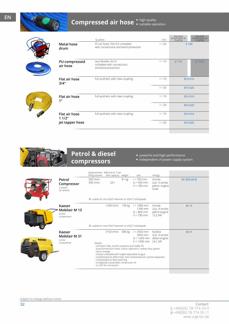
1200 l/min 190 kg l = 1080 mm 1390 mmb = 800 mmh = 790 mm
M 13
3150 l/min 580 kg l = 2920 mm 3450 mmb = 1260 mmh = 1300 mm
M 31
20 l500 l/min390 l/min
81 kg l = 750 mmb = 950 mmh = 700 mm
KF-500-20-B
l [m]
l = 20
l = 10
Z 100
813 010
816 010
819 010
813 020
816 020
819 020
Z 110 Z 110 S
l = 10
l = 20
l = 10
l = 20
l = 10
l = 20
Standard compressed air
coupling
Standard compressed air
coupling
Metal hosedrum
PU-air hose 10x14,5 completewith connections and bend protection
Qualities
PU-compressedair hose
Flat air hose3/4“
Flat air hose1“
Flat air hose1 1/2“jet tapper hose
very flexible, 9x14complete with connectionsand bend protection
full-synthetic with claw coupling
full-synthetic with claw coupling
full-synthetic with claw coupling
Compressed air hose � high quality � suitable operation
Petrol & diesel compressors
� powerful and high performance � independent of power supply system
PetrolCompressor
Honda2cyl. 4-strokepetrol engine 4 kW2 piston
air wheels
effective at 7 bartank capacity
displacementfilling volume weight size energy
usable for one VOGT Hammer or VOGT TurboSpade
Kaeser Mobilair M 13
Honda2cyl. 4-strokepetrol engine13,2 kWscrew
compressor
usable for one VOGT Hammer or VOGT TurboSpade
Kaeser Mobilair M 31
Details:- corrosion-free, scratch-resistant and stable PE sound protection hood. Colour optional in: yellow, blue, green, red or orange- chassis unbraked with height-adjustable tongue- compressed-air-aftercooler and compressed-air-cyclone-separator- compressed air-back warming- ecologically sustainable compressor oil- 2x 3/4“ Air connection
Kubota3cyl. 4-strokediesel engine24,1 kWscrew
compressor
EN

33Subject to change without notice
Contact: +49(0)92 78-774 33-0 +49(0)92 78-774 33-11www.vogt-tec.de
M 13 E
285 l/min30 l
425 l/min70 l
450 l/min370 l/min
660 l/min545 l/min
79 kg
118 kg
l = 640 mmb = 570 mmh = 1010 mm
l = 1060 mmb = 700 mmh = 630 mm
230 V16 A2,2 kW
400 V16 A3 kW
PC 660/70 PD
KC 400/30 PW
13 kg l = 270 mmb = 500 mmh = 700 mm
285 l/min30 l
450 l/min370 l/min
80 kg l = 870 mmb = 560 mmh = 590 mm
230 V16 A2,2 kW
PCA 450/30 PW
801 001
---33 l
7 kg VDP 33K
1200 l/min 190 kg l = 1080 mm 1390 mmb = 800 mmh = 790 mm
400 V32 A7,5 kW
230 V Compressor
effective at 7 bartank capacity
displacementfilling volume weight size energy
� robust and long lasting � with 230 V, useable anywhere
VOGT CompactRack
Kaeser Premium Compakt400/30 PW2 pistonPico paper air filter
Retrofit &removablefor KC 400/30 PW
usable for one VOGT Hammer or VOGT TurboSpade
Enables quick relocation. Compact holder forVOGT Hammer, tools, accessories and hose drumDelivery without drum hose, Compressor, Hammer, tool and accessories
KaeserPremium Car450/30 PW2 pistonPico paper air filterAir wheels
usable for one VOGT Hammer or VOGT TurboSpade
additional compressed air reservoir is providing air pressureif compressor works at upper limit increasing the air volume by soil detonation with VOGT Soil Aerator
PufferspeicherAluminiumPressure tested to 30 bar
KaeserMobilairM 13 E
400 V Compressor
effective at 7 bartank capacity
displacementfilling volume weight size energy
� powerful and long lasting � airpressure for more then one machine
Kaeser Premium Car660/70 D
usable for one VOGT Hammer or VOGT TurboSpade
usable for up to five VOGT Hammers or VOGT TurboSpades
2 pistonpico paper air filterair wheels
screwcompressor
560 - 2000 l/min
70 l
Vehicle engine-drivenrotary screw compressor• No own power source necessary• No unnecessary waste of space in the cargo space• Less additional noise• Built-in invisible underfloor
73 kg V 250 UF
Underfloor compressor
Lieferleistung-Tankinhalt Gewicht
UnderfloorcompressorV 250 UF
EN
34Subject to change without notice
Contact: +49(0)92 78-774 33-0 +49(0)92 78-774 33-11
www.vogt-tec.de
Z 200 Z 200 S
Z 250 Z 250 S
Z 700
Z 410
Z 260 Z 260 S
Z 400 Z 400 S
Z 230 Z 230 S
VH 25VH 30
VH 50.18VH 60.18
VH 25VH 30
VH 60.18VTS 60
VH 50.18 VTS 50
Z 220 Z 220 S
Z 240 Z 240 S
Z 300 Z 300 S
Z 510
Z 500
Z 550
Z 600
Z 625
Z 650
Z 850
Z 925
Z 950
870 012
870 005
870 007
832 010
834 010
Standard compressed air
coupling
Standard compressed air
coupling
VH 25VH 30
VH 50.18VH 60.18
Z 630
Z 660
835 010
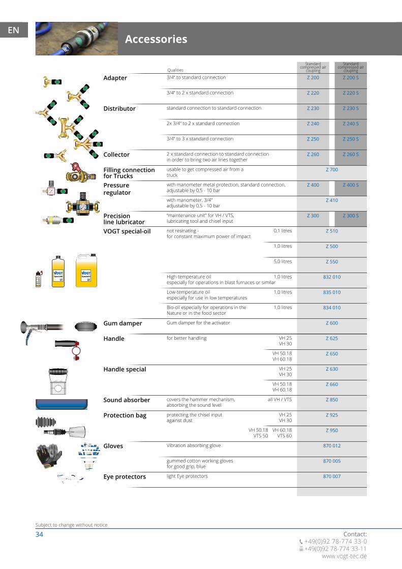
Adapter 3/4“ to standard connectionQualities
Distributor
3/4“ to 2 x standard connection
0,1 litres
Collector
Filling connectionfor TrucksPressure regulator
Precisionline lubricatorVOGT special-oil
standard connection to standard connection
2x 3/4“ to 2 x standard connection
3/4“ to 3 x standard connection
2 x standard connection to standard connectionin order to bring two air lines together
usable to get compressed air from atruck
with manometer metal protection, standard connection,adjustable by 0,5 - 10 bar
with manometer, 3/4“adjustable by 0,5 - 10 bar
“maintenance unit” for VH / VTS,lubricating tool and chisel input
not resinating -for constant maximum power of impact
1,0 litres
5,0 litres
Gum damper
Handle
Sound absorber
Protection bag
Gloves
Eye protectors
Gum damper for the activator
for better handling
covers the hammer mechanism,absorbing the sound level
protecting the chisel inputagainst dust
Vibration absorbing glove
gummed cotton working glovesfor good grip, blue
light Eye protectors
High-temperature oilespecially for operations in blast furnaces or similar
1,0 litres
Bio-oil especially for operations in theNature or in the food sector
1,0 litres
all VH / VTS
Low-temperature oilespecially for use in low temperatures
1,0 litres
Handle special
AccessoriesEN
35Subject to change without notice
Contact: +49(0)92 78-774 33-0 +49(0)92 78-774 33-11www.vogt-tec.de
861 008
150 240
050 230
861 005
025 230
861 004
861 001
025 200
050 200
025 210
050 210
025 250
050 250
861 013
861 014
861 015
870 011
VH 50.18VH 60.18
VTS 50VTS 60
VH 25VH 30
VH 60.18VTS 60
VH 50.18VTS 50
VH 25VH 30
VH 25VH 30
VH 25VH 30
VTS 50VTS 60
VH 60.18VTS 60
VH 50.18VTS 50
VH 60.18VTS 60
VH 50.18VTS 50
VH 60.18VTS 60
VH 50.18VTS 50
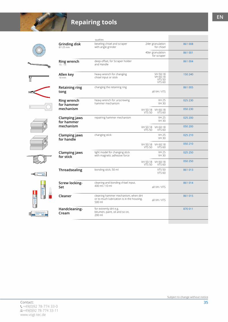
Grinding disk
Repairing tools
beveling chisel and scraperwith angle grinder
qualities
24er granulationfor chisel
Ring wrench
Allen key
Retaining ringtong
Ring wrenchfor hammermechanism
40er granulationfor scraper
deep-offset, for Scraper holderand Handle
heavy wrench for changingchisel input or stick
changing the retaining ring
heavy wrench for unscrewinghammer mechanism
Clamping jawsfor hammermechanism
Clamping jawsfor handle
Clamping jawsfor stick
Threadsealing
Screw locking-Set
Cleaner
Handcleaning-Cream
all VH / VTS
all VH / VTS
repairing hammer mechanism
changing stick
light model for changing stickwith magnetic adhesive force
bonding stick, 50 ml
cleaning and bonding chisel input,400 ml / 10 ml
cleaning hammer mechanism, when dirtor to much lubrication is in the housing,500 ml
for extremly dirt e.g.bitumen, paint, oil and so on,200 ml
Ø 125 mm
15 - 19
18 mm
all VH / VTS
EN
36Subject to change without notice
Contact: +49(0)92 78-774 33-0 +49(0)92 78-774 33-11
www.vogt-tec.de
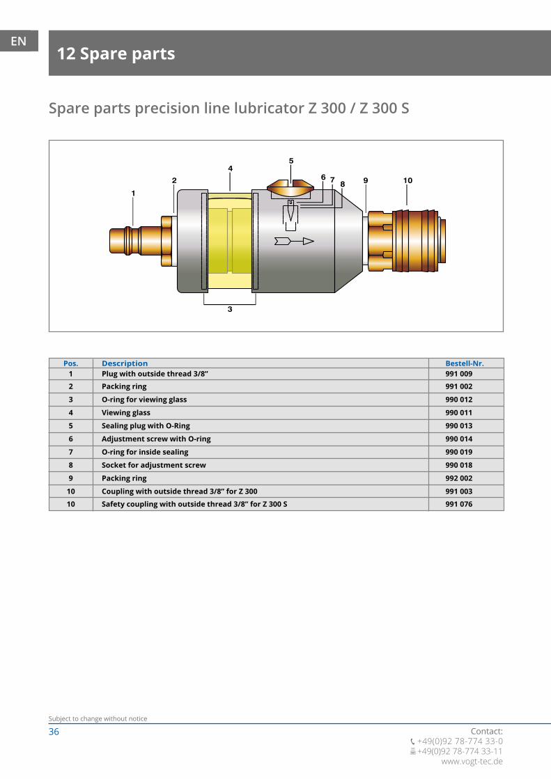
Safety coupling with outside thread 3/8” for Z 300 S 991 07610
12 Spare partsEN
Spare parts precision line lubricator Z 300 / Z 300 S
Pos.Plug with outside thread 3/8”
Packing ring
O-ring for viewing glass
Viewing glass
Sealing plug with O-Ring
Adjustment screw with O-ring
O-ring for inside sealing
Socket for adjustment screw
Packing ring
Coupling with outside thread 3/8” for Z 300
1
2
3
4
5
6
7
8
9
10
Description Bestell-Nr.991 009
991 002
990 012
990 011
990 013
990 014
990 019
990 018
992 002
991 003

37Subject to change without notice
Contact: +49(0)92 78-774 33-0 +49(0)92 78-774 33-11www.vogt-tec.de
VH 10-30
We are thrilled to be able to present our new, vibration-damped VOGT multi tool in the very near future.
You can find further information at: www.vogt-tec.de.
facebook.com/vogtbaugeraete youtube.com/vogtbaugeraete
• Clean machines
• Refurbish joints
• Use in industrial applications
• Work in constricted spaces
EN

38Subject to change without notice
Contact: +49(0)92 78-774 33-0 +49(0)92 78-774 33-11
www.vogt-tec.de
EN
15 1716 18 19 2010 11
12
12.1
1
5.1
2 3
3
9
4
5
5.1
5.3
5.2
4
6
6
7
13 14
5.35.2
5
5.2
6
6
(07-2017)
VH25
VH25D
Pos.1 Actuator conventional, complete (Pos. 2 - 6)
Hand piece, round with O-RingValve springValve with O-ringConnecting hose complete-set (Pos. 5.1 - 5.3)Bend protection device sideBend protection connecting sideConnecting hoseEngaging lever with bolt Delta Handle, complete (Pos. 3 - 6, 9)Seal for sticking the stem threads - Only required for delta handleConnection fitting with O-RingStick with thread
Screwed connectionRammer complete mounted (Pos. 11, 13 - 20)Housing with Tool holder mounted (Pos. 15, 16)Copper gasketPistonHousingTool holderScrew locking-Set (not illustrated) for cleaning and locking the Tool holderBall set (3 pcs.)Spring for clamping sleeveClamping sleeveRetaining ringTransport case (not illustrated)
Operation Manual EN (not illustrated) - Further languages on request
030 011030 012025 014025 015025 017025 017-1025 017-2025 017-3030 018130 011861 013130 012025 016-70025 016-90025 016-110025 016-130025 020025 060025 061025 021025 022025 023025 025861 014025 024025 026025 027025 029025 030-60025 030-100
0XX 035-90
890 009
23455.15.25.3678910
11
1212.11314151616.11718192030
31
VH 25-70 / VH 25-70 D / Total Length 70 cm (Stick Length 32 cm)VH 25-90 / VH 25-90 D / Total Length 90 cm (Stick Length 52 cm)VH 25-110 / VH 25-110 D / Total Length 110 cm (Stick Length 72 cm)
VH 25-70, VH 25-90VH 25-110, VH 25-130VH 25-70 D, VH 25-90 D
VH 25-130 / VH 25-130 D / Total Length 130 cm (Stick Length 92 cm)
Pos. 13Pos. 13
Pos. 20Pos. 20Pos. 20
Spare parts list VH 25D / VH 25
Description Item-No.
Pos. 13, 20
Pos. 16.1, 20
39Subject to change without notice
Contact: +49(0)92 78-774 33-0 +49(0)92 78-774 33-11www.vogt-tec.de
EN
15 1716 18 19 2010 11
12
1
5.1
2 3
3
9
4
5
5.1
5.3
5.2
4
6
6
7
13 14
5.35.2
56
6
(07-2017)
VH30
VH30D
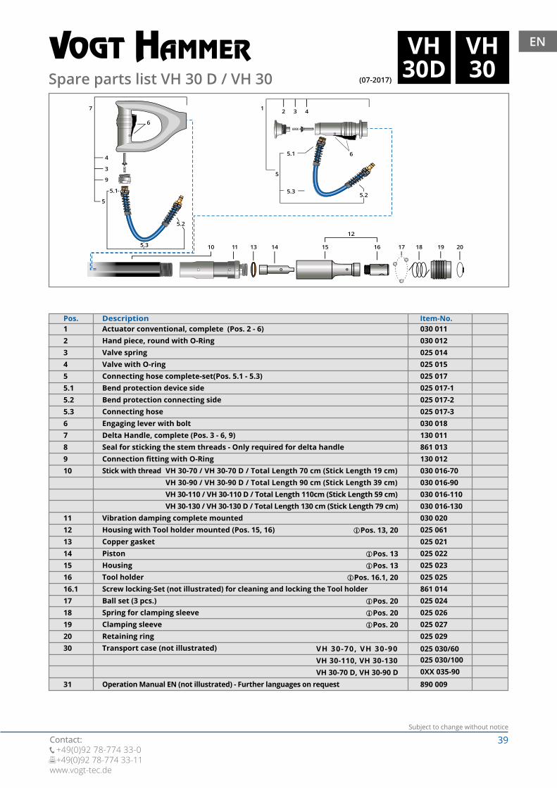
Pos.1
Vibration damping complete mountedHousing with Tool holder mounted (Pos. 15, 16)Copper gasketPistonHousingTool holderScrew locking-Set (not illustrated) for cleaning and locking the Tool holderBall set (3 pcs.)Spring for clamping sleeveClamping sleeveRetaining ringTransport case (not illustrated)
Operation Manual EN (not illustrated) - Further languages on request
030 011030 012025 014025 015025 017025 017-1025 017-2025 017-3030 018130 011861 013130 012030 016-70030 016-90030 016-110030 016-130030 020025 061025 021025 022025 023025 025861 014025 024025 026025 027025 029025 030/60025 030/1000XX 035-90
890 009
23455.15.25.3678910
11121314151616.11718192030
31
VH 30-70 / VH 30-70 D / Total Length 70 cm (Stick Length 19 cm)VH 30-90 / VH 30-90 D / Total Length 90 cm (Stick Length 39 cm)VH 30-110 / VH 30-110 D / Total Length 110cm (Stick Length 59 cm)
VH 30-70, VH 30-90VH 30-110, VH 30-130VH 30-70 D, VH 30-90 D
VH 30-130 / VH 30-130 D / Total Length 130 cm (Stick Length 79 cm)
Pos. 13Pos. 13
Pos. 20Pos. 20Pos. 20
Spare parts list VH 30 D / VH 30
Actuator conventional, complete (Pos. 2 - 6)Hand piece, round with O-RingValve springValve with O-ringConnecting hose complete-set(Pos. 5.1 - 5.3)Bend protection device sideBend protection connecting sideConnecting hoseEngaging lever with bolt Delta Handle, complete (Pos. 3 - 6, 9)Seal for sticking the stem threads - Only required for delta handleConnection fitting with O-RingStick with thread
Description Item-No.
Pos. 13, 20
Pos. 16.1, 20
40Subject to change without notice
Contact: +49(0)92 78-774 33-0 +49(0)92 78-774 33-11
www.vogt-tec.de
EN
15 1716 18 19 2010 11
12
12.1
1
5.1
2 3
3
9
4
5
5.1
5.3
5.2
4
6
6
7
13 14
5.35.2
5
5.2
6
6
(07-2017)
VH50
VH50D
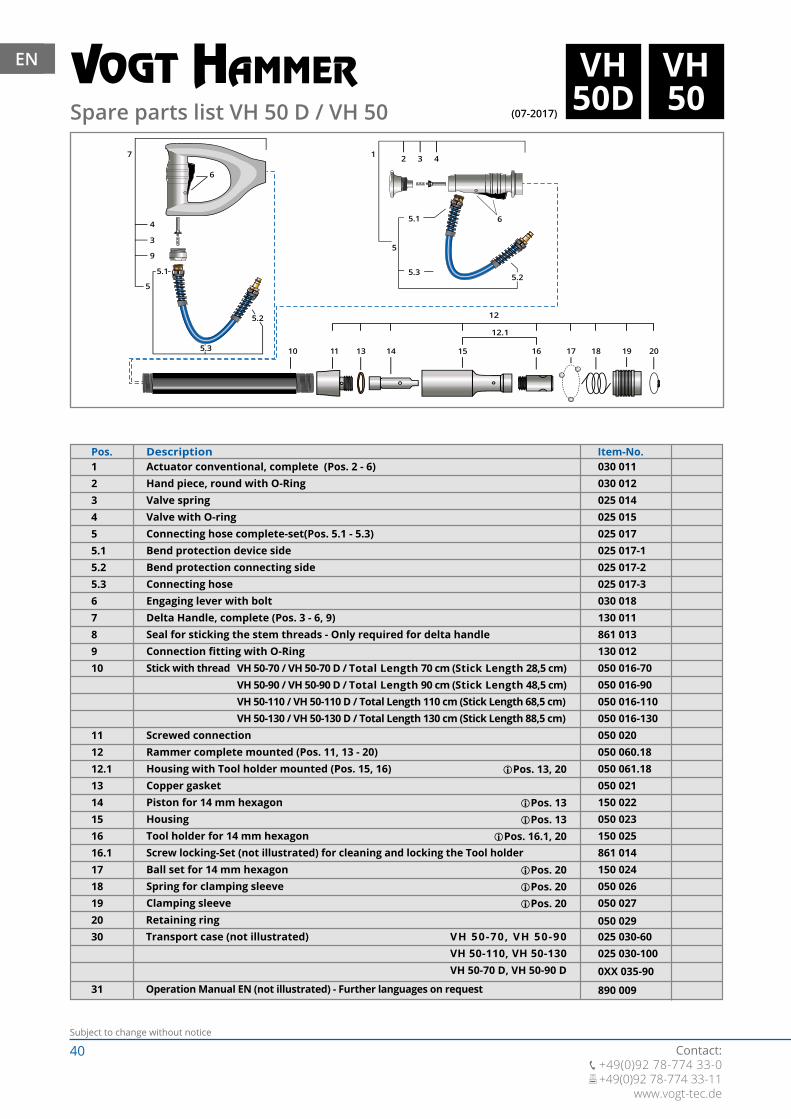
Pos.1
Screwed connectionRammer complete mounted (Pos. 11, 13 - 20)Housing with Tool holder mounted (Pos. 15, 16)Copper gasketPiston for 14 mm hexagon HousingTool holder for 14 mm hexagon Screw locking-Set (not illustrated) for cleaning and locking the Tool holderBall set for 14 mm hexagon Spring for clamping sleeveClamping sleeveRetaining ringTransport case (not illustrated)
030 011030 012025 014025 015025 017025 017-1025 017-2025 017-3030 018130 011861 013130 012050 016-70050 016-90050 016-110050 016-130050 020050 060.18050 061.18050 021150 022050 023150 025861 014150 024050 026050 027050 029025 030-60025 030-100
0XX 035-90
890 009
23455.15.25.3678910
111212.11314151616.11718192030
31
VH 50-70 / VH 50-70 D / Total Length 70 cm (Stick Length 28,5 cm)VH 50-90 / VH 50-90 D / Total Length 90 cm (Stick Length 48,5 cm)VH 50-110 / VH 50-110 D / Total Length 110 cm (Stick Length 68,5 cm)
VH 50-70, VH 50-90VH 50-110, VH 50-130VH 50-70 D, VH 50-90 D
Operation Manual EN (not illustrated) - Further languages on request
VH 50-130 / VH 50-130 D / Total Length 130 cm (Stick Length 88,5 cm)
Pos. 20Pos. 20Pos. 20
Pos. 13Pos. 13
Spare parts list VH 50 D / VH 50
Actuator conventional, complete (Pos. 2 - 6)Hand piece, round with O-RingValve springValve with O-ringConnecting hose complete-set(Pos. 5.1 - 5.3)Bend protection device sideBend protection connecting sideConnecting hoseEngaging lever with bolt Delta Handle, complete (Pos. 3 - 6, 9)Seal for sticking the stem threads - Only required for delta handleConnection fitting with O-RingStick with thread
Description Item-No.
Pos. 13, 20
Pos. 16.1, 20

41Subject to change without notice
Contact: +49(0)92 78-774 33-0 +49(0)92 78-774 33-11www.vogt-tec.de
EN
15 1716 18 19 2010 11
12
1
5.1
2 3
3
9
4
5
5.1
5.3
5.2
4
6
6
7
13 14
5.35.2
56
6
(07-2017)
VH60
VH60D
Pos.1 030 011
030 012025 014025 015025 017025 017-1025 017-2025 017-3030 018130 011861 013130 012060 016-70060 016-90060 016-110060 016-130060 020050 061.18050 021150 022050 023150 025861 014150 024050 026050 027050 029025 030-60025 030-1000XX 035-90890 009
23455.15.25.3678910
11121314151616.11718192030
31
VH 60-70 / VH 60-70 D / Total Length 70 cm (Stick Length 15 cm)VH 60-90 / VH 60-90 D / Total Length 90 cm (Stick Length 35 cm)VH 60-110 / VH 60-110 D / Total Length 110 cm (Stick Length 55 cm)
VH 60-70, VH 60-90VH 60-110, VH 60-130VH 60-70 D, VH 60-90 D
VH 60-130 / VH 60-130 D / Total Length 130 cm (Stick Length 75 cm)
Pos. 20Pos. 20Pos. 20
Pos. 13Pos. 13
Spare parts list VH 60 D / VH 60
Actuator conventional, complete (Pos. 2 - 6)Hand piece, round with O-RingValve springValve with O-ringConnecting hose complete-set (Pos. 5.1 - 5.3)Bend protection device sideBend protection connecting sideConnecting hoseEngaging lever with bolt Delta Handle, complete (Pos. 3 - 6, 9)Seal for sticking the stem threads - Only required for delta handleConnection fitting with O-RingStick with thread
Description Item-No.
Vibration damping complete mountedHousing with Tool holder mounted (Pos. 15, 16)Copper gasketPistonHousingTool holderScrew locking-Set (not illustrated) for cleaning and locking the Tool holderBall set (3 pcs.)Spring for clamping sleeveClamping sleeveRetaining ringTransport case (not illustrated)
Operation Manual EN (not illustrated) - Further languages on request
Pos. 13, 20
Pos. 16.1, 20

42Subject to change without notice
Contact: +49(0)92 78-774 33-0 +49(0)92 78-774 33-11
www.vogt-tec.de
EN
15 1716 18 19 2010 11
12
12.1
1
5.1
2 3
3
9
4
5
5.1
5.3
5.2
4
6
6
7
13 14
5.35.2
5
5.2
6
6
(07-2017)
VH50.18
VH50.18D
Pos.1
Stick connection fittingRammer complete mounted (Pos. 11, 13 - 20)Housing with Tool holder mounted (Pos. 15, 16)Copper gasketPiston for 18 mm hexagon HousingTool holder for 18 mm hexagon Screw locking-Set (not illustrated) for cleaning and locking the Tool holderBall set for 18 mm hexagon Spring for clamping sleeveClamping sleeveRetaining ringTransport case (not illustrated)
030 011030 012025 014025 015025 017025 017-1025 017-2025 017-3030 018130 011861 013130 012050 016-70050 016-90050 016-110050 016-130050 020050 060.18050 061.18050 021150 022050 023150 025861 014150 024050 026050 027050 029025 030-60025 030-100
0XX 035-90
890 009
23455.15.25.3678910
111212.11314151616.11718192030
31
VH 50-70.18 / VH 50-70.18 D / Total Length 70 cm (Stick Length 28,5 cm)VH 50-90.18 / VH 50-90.18 D / Total Length 90 cm (Stick Length 48,5 cm)VH 50-110.18 / VH 50-110.18 D / Total Length 110 cm (Stick Length 68,5 cm)
VH 50-70.18, VH 50-90.18VH 50-110.18, VH 50-130.18VH 50-70.18 D, VH 50-90.18 D
Operation Manual EN (not illustrated) - Further languages on request
VH 50-130.18 / VH 50-130.18 D / Total Length 130 cm (Stick Length 88,5 cm)
Pos. 20Pos. 20Pos. 20
Pos. 13Pos. 13
Spare parts list VH 50.18 D / VH 50.18
Actuator conventional, complete (Pos. 2 - 6)Hand piece, round with O-RingValve springValve with O-ringConnecting hose complete-set(Pos. 5.1 - 5.3)Bend protection device sideBend protection connecting sideConnecting hoseEngaging lever with bolt Delta Handle, complete (Pos. 3 - 6, 9)Seal for sticking the stem threads - Only required for delta handleConnection fitting with O-RingStick with thread
Description Item-No.
Pos. 13, 20
Pos. 16.1, 20
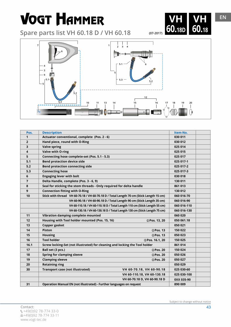
43Subject to change without notice
Contact: +49(0)92 78-774 33-0 +49(0)92 78-774 33-11www.vogt-tec.de
EN
15 1716 18 19 2010 11
12
1
5.1
2 3
3
9
4
5
5.1
5.3
5.2
4
6
6
7
13 14
5.35.2
56
6
(07-2017)
VH60.18
VH60.18D
Pos.1 030 011
030 012025 014025 015025 017025 017-1025 017-2025 017-3030 018130 011861 013130 012060 016-70060 016-90060 016-110060 016-130060 020050 061.18050 021150 022050 023150 025861 014150 024050 026050 027050 029025 030-60025 030-1000XX 035-90890 009
23455.15.25.3678910
11121314151616.11718192030
31
VH 60-70.18 / VH 60-70.18 D / Total Length 70 cm (Stick Length 15 cm)VH 60-90.18 / VH 60-90.18 D / Total Length 90 cm (Stick Length 35 cm)VH 60-110.18 / VH 60-110.18 D / Total Length 110 cm (Stick Length 55 cm)
VH 60-70.18, VH 60-90.18VH 60-110.18, VH 60-130.18VH 60-70.18 D, VH 60-90.18 D
VH 60-130.18 / VH 60-130.18 D / Total Length 130 cm (Stick Length 75 cm)
Pos. 20Pos. 20Pos. 20
Pos. 13Pos. 13
Spare parts list VH 60.18 D / VH 60.18
Actuator conventional, complete (Pos. 2 - 6)Hand piece, round with O-RingValve springValve with O-ringConnecting hose complete-set (Pos. 5.1 - 5.3)Bend protection device sideBend protection connecting sideConnecting hoseEngaging lever with bolt Delta Handle, complete (Pos. 3 - 6, 9)Seal for sticking the stem threads - Only required for delta handleConnection fitting with O-RingStick with thread
Description Item-No.
Vibration damping complete mountedHousing with Tool holder mounted (Pos. 15, 16)Copper gasketPistonHousingTool holderScrew locking-Set (not illustrated) for cleaning and locking the Tool holderBall set (3 pcs.)Spring for clamping sleeveClamping sleeveRetaining ringTransport case (not illustrated)
Operation Manual EN (not illustrated) - Further languages on request
Pos. 13, 20
Pos. 16.1, 20
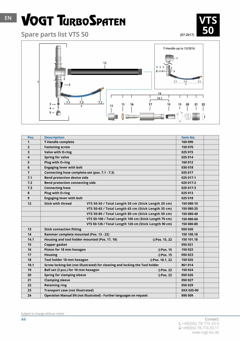
44Subject to change without notice
Contact: +49(0)92 78-774 33-0 +49(0)92 78-774 33-11
www.vogt-tec.de
EN
(07-2017)
VTS50
16 17 1918 20 21 2213 15 16 17 20 21 22
14.1
14
1
12
77.1 7.3 7.2
543
6
2
8 4 3
77.1 7.3 7.2
9
2
Spare parts list VTS 50
Pos.T-Handle completeFastening screw
160 090150 070
Valve with O-ringSpring for valvePlug with O-ringEngaging lever with boltConnecting hose complete-set (pos. 7.1 - 7.3)Bend protection device sideBend protection connecting sideConnecting hose
Description Item-No.
025 015025 014160 012030 018025 017025 017-1025 017-2025 017-3
12345677.17.27.3
Stick connection fitting
Stick with thread
Rammer complete mounted (Pos. 13 - 22)Housing and tool holder mounted (Pos. 17, 18)Copper gasketPiston for 18 mm hexagonHousingTool holder 18 mm hexagonScrew locking-Set (not illustrated) for cleaning and locking the Tool holderBall set (3 pcs.) for 18 mm hexagonSpring for clamping sleeveClamping sleeveRetaining ringTransport case (not illustrated)Operation Manual EN (not illustrated) - Further languages on request
050 020
150 080-10150 080-25150 080-40150 080-60150 080-80
150 100.18150 101.18050 021150 022050 023150 025861 014150 024050 026050 027050 0290XX 035-90890 009
VTS 50-65 / Total Length 65 cm (Stick Length 35 cm) VTS 50-80 / Total Length 80 cm (Stick Length 50 cm) VTS 50-100 / Total Length 100 cm (Stick Length 70 cm) VTS 50-120 / Total Length 120 cm (Stick Length 90 cm)
VTS 50-50 / Total Length 50 cm (Stick Length 20 cm)
Pos. 15, 22
Pos. 15Pos. 15
Pos. 18.1, 22
Pos. 22Pos. 22
13
12
1414.11516171818.1192021222324
Plug with O-ringEngaging lever with bolt
025 013025 018
89
T-Handle up to 12/2016
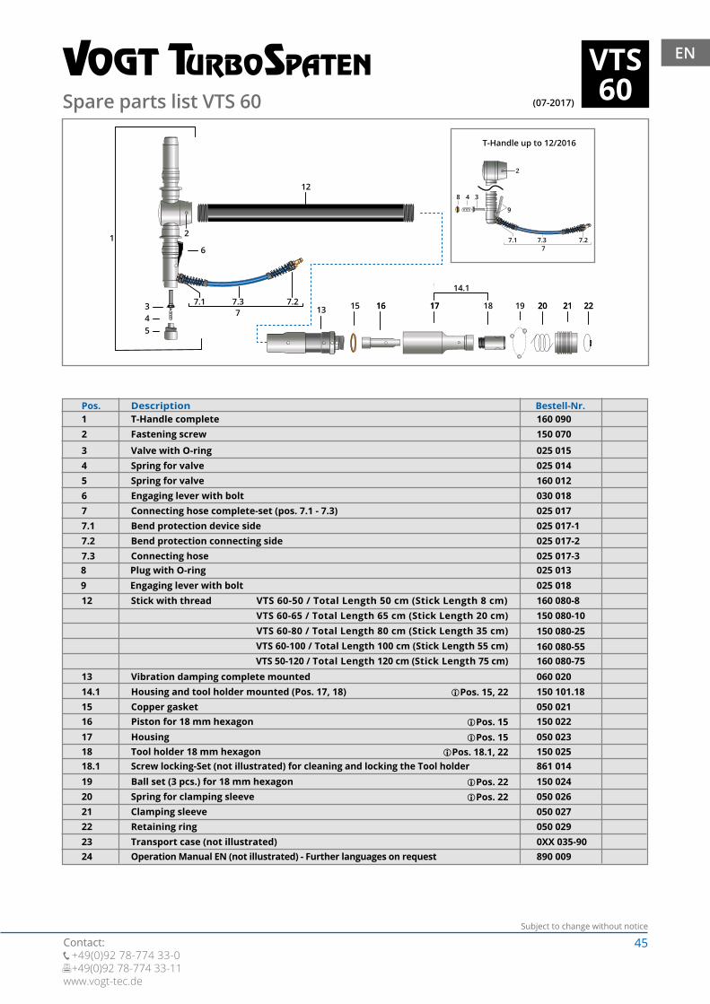
45Subject to change without notice
Contact: +49(0)92 78-774 33-0 +49(0)92 78-774 33-11www.vogt-tec.de
EN
(07-2017)
VTS60
1
16 17 1918 20 21 2213 15 16 17 20 21 22
14.1
14
12
77.1 7.3 7.2
543
6
2
8 4 3
77.1 7.3 7.2
9
2
Spare parts list VTS 60
Pos.T-Handle completeFastening screw
160 090150 070
Valve with O-ringSpring for valveSpring for valveEngaging lever with boltConnecting hose complete-set (pos. 7.1 - 7.3)Bend protection device sideBend protection connecting sideConnecting hose
Description Bestell-Nr.
025 015025 014160 012030 018025 017025 017-1025 017-2025 017-3
12
345677.17.27.3
Stick with thread
Vibration damping complete mountedHousing and tool holder mounted (Pos. 17, 18)Copper gasketPiston for 18 mm hexagonHousingTool holder 18 mm hexagonScrew locking-Set (not illustrated) for cleaning and locking the Tool holderBall set (3 pcs.) for 18 mm hexagonSpring for clamping sleeveClamping sleeveRetaining ringTransport case (not illustrated)Operation Manual EN (not illustrated) - Further languages on request
160 080-8150 080-10150 080-25160 080-55160 080-75060 020150 101.18050 021150 022050 023150 025861 014150 024050 026050 027
890 009
VTS 60-65 / Total Length 65 cm (Stick Length 20 cm) VTS 60-80 / Total Length 80 cm (Stick Length 35 cm) VTS 60-100 / Total Length 100 cm (Stick Length 55 cm) VTS 50-120 / Total Length 120 cm (Stick Length 75 cm)
VTS 60-50 / Total Length 50 cm (Stick Length 8 cm)
Pos. 15, 22
Pos. 15Pos. 15
Pos. 18.1, 22
Pos. 22Pos. 22
050 0290XX 035-90
12
1314.11516171818.1192021222324
Plug with O-ringEngaging lever with bolt
025 013025 018
89
T-Handle up to 12/2016
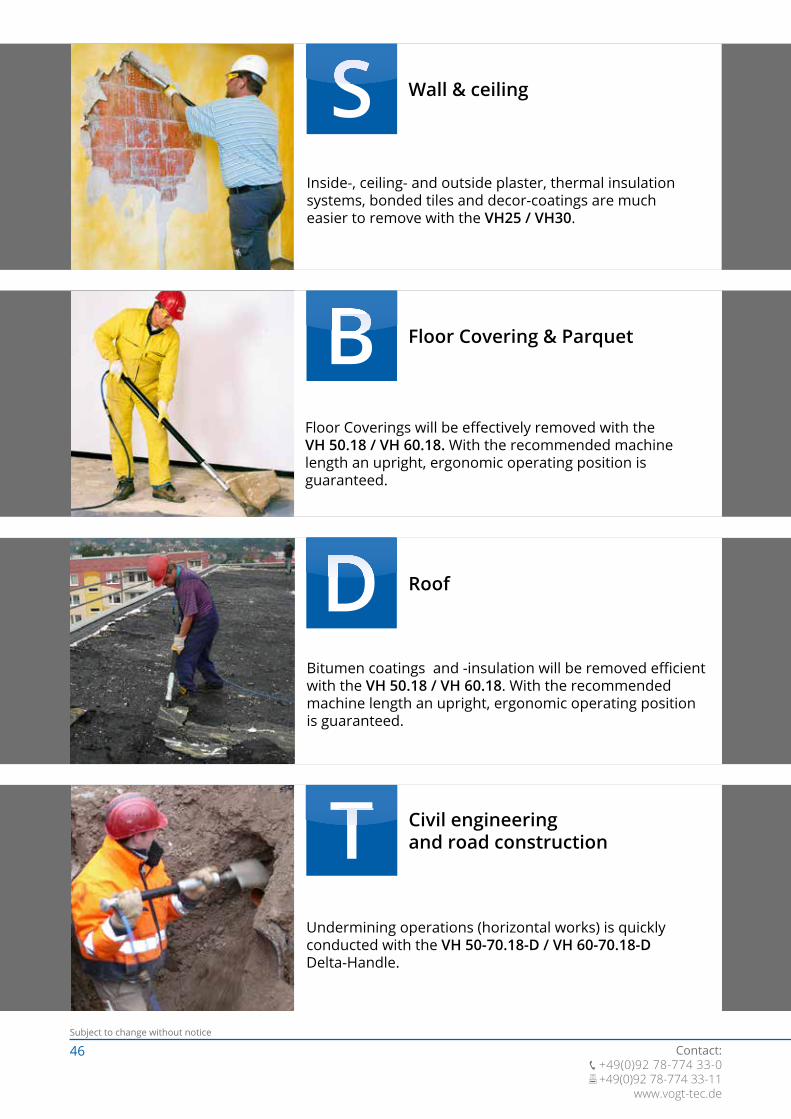
46Subject to change without notice
Contact: +49(0)92 78-774 33-0 +49(0)92 78-774 33-11
www.vogt-tec.de
Wall & ceiling
Inside-, ceiling- and outside plaster, thermal insulation systems, bonded tiles and decor-coatings are much easier to remove with the VH25 / VH30.
Floor Covering & Parquet
Floor Coverings will be effectively removed with the VH 50.18 / VH 60.18. With the recommended machine length an upright, ergonomic operating position is guaranteed.
Roof
Bitumen coatings and -insulation will be removed efficient with the VH 50.18 / VH 60.18. With the recommended machine length an upright, ergonomic operating position is guaranteed.
Civil engineering and road construction
Undermining operations (horizontal works) is quickly conducted with the VH 50-70.18-D / VH 60-70.18-D Delta-Handle.

47Subject to change without notice
Contact: +49(0)92 78-774 33-0 +49(0)92 78-774 33-11www.vogt-tec.de
VTS VOGT TurboSpade
The compressed air spade VTS 50 / VTS 60 is an effective machine for digging, compacting, break-up and expose.
VTS VOGT TurboSpadewith angled rammer
By the 25° angled rammer mechanism can the material efficiently and ergonomical compacted.
VL VOGT Air Lance
The VOGT Air Lance is used to uncover roots and supply lines. As well, the VL suits very good for dry cleaning of armoured concrete elements, plaster joints, construction and agricultural machines.
VSLVBL
The VOGT Soil Aerator and Blasting Lance reaches deep-set, compacted soil layer. The aeration hole will be filled up with open-pored granulate (Terramol), which removes waterlogging long-term and enables oxygen to reach the roots.
VOGT Soil Aerator / VOGT Blasting Lance
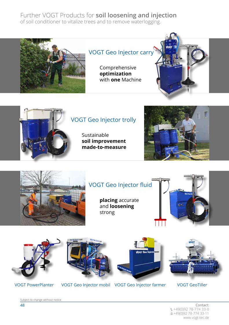
48Subject to change without notice
Contact: +49(0)92 78-774 33-0 +49(0)92 78-774 33-11
www.vogt-tec.de
VOGT PowerPlanter VOGT Geo Injector mobil VOGT Geo Injector farmer VOGT GeoTiller
VOGT Geo Injector trolly
Sustainablesoil improvementmade-to-measure
Further VOGT Products for soil loosening and injection of soil conditioner to vitalize trees and to remove waterlogging.
VOGT Geo Injector carry
Comprehensiveoptimizationwith one Machine
VOGT Geo Injector fluid
placing accurateand looseningstrong

49Subject to change without notice
Contact: +49(0)92 78-774 33-0 +49(0)92 78-774 33-11www.vogt-tec.de
WorkTec
+49(0)92 78-774 33-0 +49(0)92 78-774 33-11
OrderFax: +49(0)92 78-774 33-11 / Email: [email protected]
Firm Customer ID
Fax
Contact person
Street
Postcode / Place
Phone
Mobile
Amount Article description Article No Price €
Date, Place Signature

50Subject to change without notice
Contact: +49(0)92 78-774 33-0 +49(0)92 78-774 33-11
www.vogt-tec.de
Notes

51Subject to change without notice
Contact: +49(0)92 78-774 33-0 +49(0)92 78-774 33-11www.vogt-tec.de
Notes
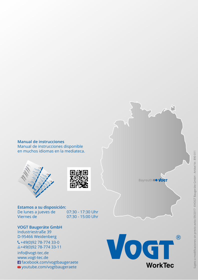
WorkTec
BayreuthWorkTec
VOGT Baugeräte GmbHIndustriestraße 39D-95466 Weidenberg +49(0)92 78-774 33-0 +49(0)92 78-774 [email protected] facebook.com/vogtbaugeraete youtube.com/vogtbaugeraete
Estamos a su disposición:De lunes a jueves de 07:30 - 17:30 UhrViernes de 07:30 - 15:00 Uhr
Manual de instruccionesManual de instrucciones disponible en muchos idiomas en la mediateca.
Suje
to a
mod
ifica
cion
es s
in p
revi
o av
iso
09/2
017
©VO
GT
Baug
erät
e G
mbH
- Ar
tikel
Nr.
890
011
WorkTec
VOGT Druckluftgeräte
mit W
erkzeug-, Zubehör- und ErsatzteillistenOriginal
Betriebsanleitung
Stand: 08/2017
VOGT Pneumatic Power Tools
with Tools, Accessories and SparepartlistsOriginal
Operating Manual
Equipos de aire
comprim
ido VOGT
con lista de herramientas,
accesorios y piezas de repuestoM
anual de
instrucciones
original
Outils à air comprim
é VOGT
avec pièces d‘outil, accessoires
et pièces de rechange
Mode d‘em
ploi
original
DE
EN
FR
ES
NL
VOGT persluchtgereedschap
met werktuig-, accessoire-
en reserveonderdelenlijstenOriginele
handleiding
WorkTec
VOGT Druckluftgeräte
mit Werkzeug-, Zubehör- und Ersatzteillisten
Original
Betriebsanleitung
Stand: 08/2017
VOGT Pneumatic Power Tools
with Tools, Accessories and Sparepartlists
Original
Operating Manual
Equipos de aire
comprimido VOGT
con lista de herramientas,
accesorios y piezas de repuesto
Manual de
instrucciones original
Outils à air comprimé VOGT
avec pièces d‘outil, accessoires
et pièces de rechange
Mode d‘emploi original
DE
EN
FR
ES
NL
VOGT persluchtgereedschap
met werktuig-, accessoire-
en reserveonderdelenlijsten
Originele
handleiding
WorkTec
VOGT Druckluftgeräte
mit Werkzeug-, Zubehör- und Ersatzteillisten
Original
Betriebsanleitung
Stand: 08/2017
VOGT Pneumatic Power Tools
with Tools, Accessories and Sparepartlists
Original
Operating Manual
Equipos de aire
comprimido VOGT
con lista de herramientas,
accesorios y piezas de repuesto
Manual de
instrucciones original
Outils à air comprimé VOGT
avec pièces d‘outil, accessoires
et pièces de rechange
Mode d‘emploi original
DE
EN
FR
ES
NL
VOGT persluchtgereedschap
met werktuig-, accessoire-
en reserveonderdelenlijsten
Originele handleiding