MANUAL DE USUARIO USER MANUAL · 2018-09-11 · antes de retirar cualquier tapa de protección ya...
75
MANUAL DE USUARIO USER MANUAL DTP2-11/ DTP2-18 www.domuslaundry.com Especialistas en lavandería industrial desde 1922 Specialists in industrial laundry since 1922
Transcript of MANUAL DE USUARIO USER MANUAL · 2018-09-11 · antes de retirar cualquier tapa de protección ya...
MANUAL DE USUARIO USER MANUAL
DTP2-11/ DTP2-18
www.domuslaundry.com
Especialistas en lavandería industrial desde 1922Specialists in industrial laundry since 1922

1
INDICE
1 SEGURIDAD ............................................................................................................................. 6
2 CARACTERISTICAS GENERALES .......................................................................................... 7
2.1 Componentes......................................................................................................................................... 8
2.2 Vista general y dimensiones ............................................................................................................... 11
3 INSTALACION ....................................................................................................................... 12
3.1 Emplazamiento. .................................................................................................................................. 12
3.1.1 Transporte y depósito. ........................................................................................................................ 12 3.1.2. ...... Situación. ................................................................................................................................ 12 3.1.3. ...... Nivelación. .............................................................................................................................. 14
3.2 Extracción de aire ............................................................................................................................... 14
3.2.1 Entrada de aire fresco ........................................................................................................................ 14
3.2.2 Tubería de salida ................................................................................................................................ 15
3.3 Conexión eléctrica .............................................................................................................................. 17
3.4 Conexión a gas (sólo modelos a gas) ................................................................................................. 19
3.5 Sustitución de los inyectores. .............................................................................................................. 20
3.6 Vista trasera secador y datos de instalación: ..................................................................................... 21
4 FUNCIONAMIENTO .............................................................................................................. 22
4.1 Principio y descripción del funcionamiento: ...................................................................................... 22
4.2 Versiones autoservicio ........................................................................................................................ 23
4.2.1 Versión dos monederos / central de pago ........................................................................................... 24
4.2.2 Versión con un solo monedero (con selector) .................................................................................... 24
4.2.3 Edición de parámetros ........................................................................................................................ 25
4.2.4 OPTION – Opciones ........................................................................................................................... 26
4.2.5 UNCREASE CONTROL – Sistema Antiarrugas ................................................................................. 26
4.2.6 PULSE TIME – Tiempo de impulso .................................................................................................... 27
4.2.7 PULSES REQUIRED – Mínimos pulsos requeridos .......................................................................... 27
4.2.8 TEMP LOW – Temperatura baja........................................................................................................ 28
4.2.9 TEMP MID – Temperatura media ...................................................................................................... 28
4.2.10 TEMP HIGH – Temperatura alta ....................................................................................................... 28
4.2.11 COOL FACTOR – Factor de Cool ..................................................................................................... 28
4.2.12 LOST BALANCE TIME – Tiempo en espera antes de perder saldo ................................................... 29
4.2.13 DRUM TIME– Tiempo de inversión de giro del tambor .................................................................... 29
4.2.14 MEMORY RESTORE – Parámetros de Fabrica ................................................................................ 29
4.3 COUNT - Contadores ......................................................................................................................... 30
4.4 EXIT - Salir ......................................................................................................................................... 31
2
4.5 Versión OPL: ...................................................................................................................................... 32
4.5.1 Funciones asociadas a las teclas ........................................................................................................ 32
4.5.2 Información visualizada en el display ................................................................................................ 33
4.5.3 Cómo realizar un secado utilizando un programa estándar .............................................................. 33
4.5.4 Cómo realizar un secado utilizando los valores definidos por el usuario ......................................... 33
4.5.5 Edición de programas ......................................................................................................................... 34
5 ALARMAS Y AVISOS ............................................................................................................ 36
6 MANTENIMIENTO ................................................................................................................ 37
6.1 Filtro borras: ...................................................................................................................................... 37
6.2 Batería calefactora: ............................................................................................................................ 37
6.3 Extractor de aire: ............................................................................................................................... 37
7 PROBLEMAS Y SOLUCIONES ............................................................................................. 38
7.1 Tabla Problema-Causa-Solución ....................................................................................................... 38
8 INDICACIONES PARA LA RETIRADA Y ELIMINACIÓN DE LA MAQUINA. ......................... 39

3
1 SAFETY .................................................................................................................................... 41
2 GENERAL SPECIFICATIONS ................................................................................................... 42
2.1 Components ........................................................................................................................................ 43
2.2 Overview and dimensions ................................................................................................................... 46
3. INSTALATION ....................................................................................................................... 47
3.1 Position. .............................................................................................................................................. 47
3.1.1 Transport and storage. ....................................................................................................................... 47 3.1.2 ....... Location. ................................................................................................................................. 47 3.1.3 ....... Levelling. ................................................................................................................................ 49
3.2 Air extraction ...................................................................................................................................... 49
3.2.1 Fresh air inlet ..................................................................................................................................... 49
3.2.2 Output pipe ......................................................................................................................................... 50
3.3 Electrical connection .......................................................................................................................... 52
3.4 Connection to gas (only gas models) .................................................................................................. 54
3.5 Injector replacement. .......................................................................................................................... 55
3.6 Rear view of dryer and installation data: ........................................................................................... 56
4. OPERATION ......................................................................................................................... 57
4.1 Operating principle and description: ................................................................................................. 57
4.2 Self-service versions ........................................................................................................................... 58
4.2.1 Version with two coin slots / pay centre ............................................................................................. 59
4.2.2 Version with only one coin slot (with selector switch) ....................................................................... 59
4.2.3 Editing parameters ............................................................................................................................. 60
4.2.4 OPTION .............................................................................................................................................. 61
4.2.5 UNCREASE CONTROL ..................................................................................................................... 61
4.2.6 PULSE TIME ...................................................................................................................................... 61
4.2.7 PULSES REQUIRED .......................................................................................................................... 62
4.2.8 TEMP LOW ........................................................................................................................................ 62
4.2.9 TEMP MID ......................................................................................................................................... 63
4.2.10 TEMP HIGH ....................................................................................................................................... 63
4.2.11 COOL FACTOR.................................................................................................................................. 63
4.2.12 LOST BALANCE TIME ...................................................................................................................... 64
4.2.13 DRUM TIME ...................................................................................................................................... 64
4.2.14 MEMORY RESTORE .......................................................................................................................... 64
4.3 COUNT ............................................................................................................................................... 65
4.4 EXIT .................................................................................................................................................... 66
4.5 OPL Version: ...................................................................................................................................... 67
4.5.1 Key associated functions ..................................................................................................................... 67
4.5.2 Information displayed ......................................................................................................................... 68

4
4.5.3 How to run a drying cycle using a standard program ........................................................................ 68
4.5.4 How to run a drying cycle using the values defined by the user ......................................................... 68
4.5.5 Programme editing ............................................................................................................................. 69
5. ALARMS AND WARNINGS ................................................................................................... 71
6. MAINTENANCE .................................................................................................................... 72
6.1 Fluff filter: .......................................................................................................................................... 72
6.2 Heating battery: .................................................................................................................................. 72
6.3 Air extractor: ...................................................................................................................................... 72
7. TROUBLESHOOTING ........................................................................................................... 73
7.1 Problem-Cause-Solution Table........................................................................................................... 73
8. INDICATIONS FOR REMOVING AND DISPOSAL OF THE MACHINE. ................................ 74

5
MANUAL DE USO Secadoras de columna DTP2-11/DTP2-18
6
1 SEGURIDAD
Lea este manual antes de utilizar o instalar la secadora.
Guarde este manual en un lugar seguro para futuras consultas.
Este manual debe cederse con la máquina en caso de su venta a terceras personas.
Usar la máquina únicamente para secado profesional de fibras textiles tras lavado en agua.
Si detecta olor a gas:
Cierre la alimentación principal de gas y ventile la sala.
No encienda ninguna luz ni conecte un equipo eléctrico.
No use el teléfono en la misma sala.
No dejar gasolina ni otro líquido o gas inflamable cerca de la secadora.
No secar productos que hayan sido tratados o que desprendan vapores o elementos inflamables.
Tener siempre en cuenta las instrucciones descritas en las etiquetas de los materiales a secar.
No dejar la secadora funcionando sin atención.
No deje que se acumule pelusa, polvo o suciedad alrededor de la máquina.
No rociar con agua la secadora.
No se aconseja parar la secadora antes que termine el ciclo por riesgo de combustión espontánea
Se aconseja sacar la carga tan pronto finalizado el ciclo, esto reduce el riesgo de combustión espontánea.
Existe riesgo de quemaduras al retirar la carga antes de finalizar el ciclo, en caso de seleccionar una temperatura de secado elevada.
En caso de producirse una interrupción del suministro eléctrico es recomendable abrir la puerta de la secadora para evitar la combustión espontánea de la carga.
El mantenimiento e instalación solo puede realizarse por parte de personal cualificado.
Cerrar o desconectar todas las alimentaciones de la máquina al finalizar cada jornada de trabajo y antes de retirar cualquier tapa de protección ya sea para limpieza, mantenimiento o pruebas.
Es recomendable la instalación de bridas con material flexible para evitar que las vibraciones del aire produzcan ruidos excesivos en la instalación.
No se debe utilizar una máquina a gas en recintos donde se usa PER (Percloroetileno) como disolvente, ya que el contacto con llamas produce gases tóxicos y corrosivos.
El fabricante se reserva el derecho de realizar futuras modificaciones sin previo aviso.
7
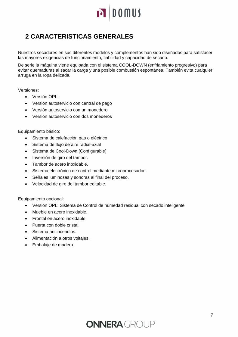
2 CARACTERISTICAS GENERALES
Nuestros secadores en sus diferentes modelos y complementos han sido diseñados para satisfacer las mayores exigencias de funcionamiento, fiabilidad y capacidad de secado.
De serie la máquina viene equipada con el sistema COOL-DOWN (enfriamiento progresivo) para evitar quemaduras al sacar la carga y una posible combustión espontánea. También evita cualquier arruga en la ropa delicada.
Versiones:
Versión OPL.
Versión autoservicio con central de pago
Versión autoservicio con un monedero
Versión autoservicio con dos monederos
Equipamiento básico:
Sistema de calefacción gas o eléctrico
Sistema de flujo de aire radial-axial
Sistema de Cool-Down.(Configurable)
Inversión de giro del tambor.
Tambor de acero inoxidable.
Sistema electrónico de control mediante microprocesador.
Señales luminosas y sonoras al final del proceso.
Velocidad de giro del tambor editable.
Equipamiento opcional:
Versión OPL: Sistema de Control de humedad residual con secado inteligente.
Mueble en acero inoxidable.
Frontal en acero inoxidable.
Puerta con doble cristal.
Sistema antiincendios.
Alimentación a otros voltajes.
Embalaje de madera

8
Las características técnicas para cada modelo se especifican en la siguiente tabla:
MODELO DTP2-11 DTP2-18
Volumen del tambor L 210x2 330x2
Capacidad (Rel. 1:18) kg 23,3 36,6
Capacidad (Rel. 1:20) kg 21 33
Producción kg/h 34 53
Diámetro tambor mm 750 750
Profundidad tambor mm 475 745
Motor tambor kW 0,25x2 0,25x2
Motor ventilador kW 0,25x2 0,25x2
Volumen de aire m3/h 500 500
Calefacción eléctrica kW 12x2 12x2
Calefacción a gas kW 12x2 12x2
Consumo GLP kg/h 0,75x2 0,75x2
Consumo Gas Natural m3/h 0,9x2 0,9x2
Peso neto ( Calef. Eléctrica) kg 260 290
2.1 Componentes
Control de la máquina:
El control de la máquina se realiza mediante un microprocesador electrónico que controla la activación y desactivación de cada sistema. La comunicación con el usuario se lleva a cabo mediante un teclado con un display gráfico situado en la parte central de la máquina.
En la versión OPL el microprocesador tiene incorporados 9 programas que el usuario puede editar.
En las versiones de autoservicio el microprocesador tiene 3 programas con baja, media y alta temperatura cuyos valores pueden ser editados.
Una sonda digital de temperatura, localizada en la parte inferior del tambor, se utiliza para mantener constante la temperatura en el interior del secador. La temperatura deseada se gradúa mediante el control electrónico anteriormente descrito y nos permite cambiar los valores entre 0 y 95ºC con la finalidad de trabajar con la temperatura óptima para cada tipo de tejido.
La sonda envía una señal a la placa electrónica y es esta última la que activa o desactiva la parte de calefacción.
El control de tiempo se realiza internamente en el microprocesador.
Al final de cada ciclo (Secado + Cool-Down) se activa automáticamente el ciclo de antiarrugas (se puede desactivar).
En versión OPL el microprocesador tiene incorporadas una indicación temporal sobre la necesidad de limpiar el filtro.
9
Calefacción:
El sistema de calefacción puede ser eléctrico o gas. Las baterías calefactoras se localiza en la parte posterior de la máquina.
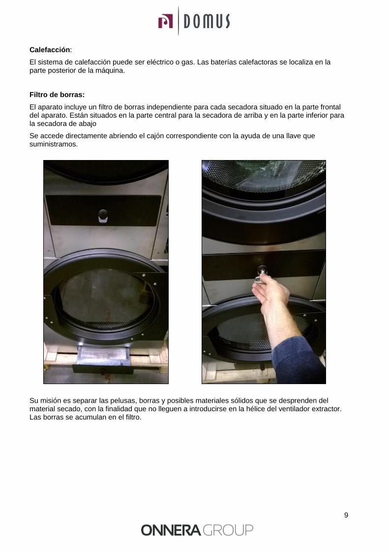
Filtro de borras:
El aparato incluye un filtro de borras independiente para cada secadora situado en la parte frontal del aparato. Están situados en la parte central para la secadora de arriba y en la parte inferior para la secadora de abajo
Se accede directamente abriendo el cajón correspondiente con la ayuda de una llave que suministramos.
Su misión es separar las pelusas, borras y posibles materiales sólidos que se desprenden del material secado, con la finalidad que no lleguen a introducirse en la hélice del ventilador extractor. Las borras se acumulan en el filtro.
10
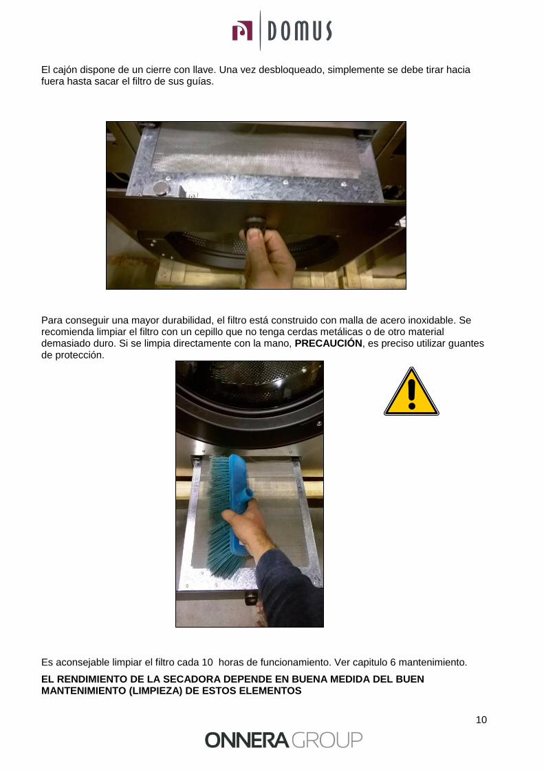
El cajón dispone de un cierre con llave. Una vez desbloqueado, simplemente se debe tirar hacia fuera hasta sacar el filtro de sus guías.
Para conseguir una mayor durabilidad, el filtro está construido con malla de acero inoxidable. Se recomienda limpiar el filtro con un cepillo que no tenga cerdas metálicas o de otro material demasiado duro. Si se limpia directamente con la mano, PRECAUCIÓN, es preciso utilizar guantes de protección.
Es aconsejable limpiar el filtro cada 10 horas de funcionamiento. Ver capitulo 6 mantenimiento.
EL RENDIMIENTO DE LA SECADORA DEPENDE EN BUENA MEDIDA DEL BUEN MANTENIMIENTO (LIMPIEZA) DE ESTOS ELEMENTOS
11
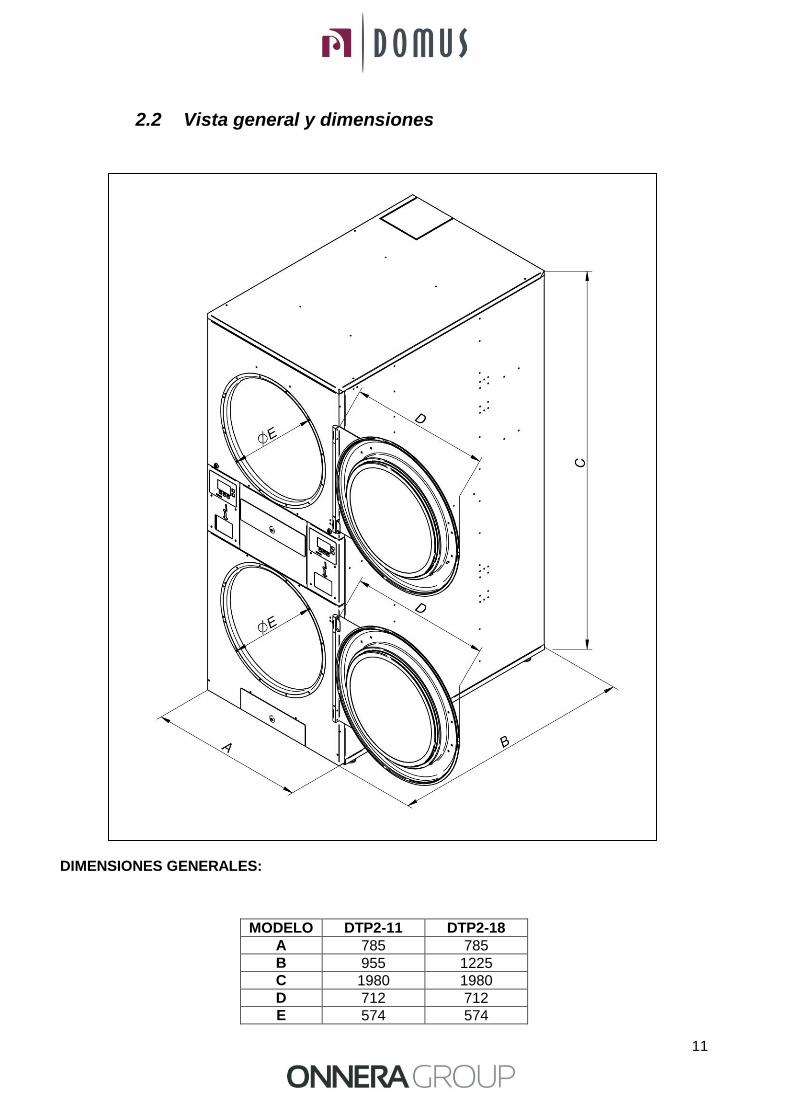
2.2 Vista general y dimensiones DIMENSIONES GENERALES:
MODELO DTP2-11 DTP2-18
A 785 785
B 955 1225
C 1980 1980
D 712 712
E 574 574
12
3 INSTALACION
Realizar la instalación según la reglamentación en vigor
3.1 Emplazamiento.
3.1.1 Transporte y depósito.
La máquina debe ser transportada siempre sobre su pallet y embalaje original para garantizar la integridad de la misma. Transportar la máquina hasta el lugar definitivo de trabajo.
Quitar el embalaje y cerciorarse que no ha habido ningún tipo de desperfecto por el transporte.
En ningún caso instale o guarde la secadora a la intemperie.
Si la máquina tiene que estar depositada durante un periodo de tiempo, cubrirla con su embalaje original para protegerla de agentes externos y se mantenga en las condiciones ambientales óptimas. Así mismo se recomienda desconectarla de la red de alimentación eléctrica, vapor y gas.
3.1.2. Situación.
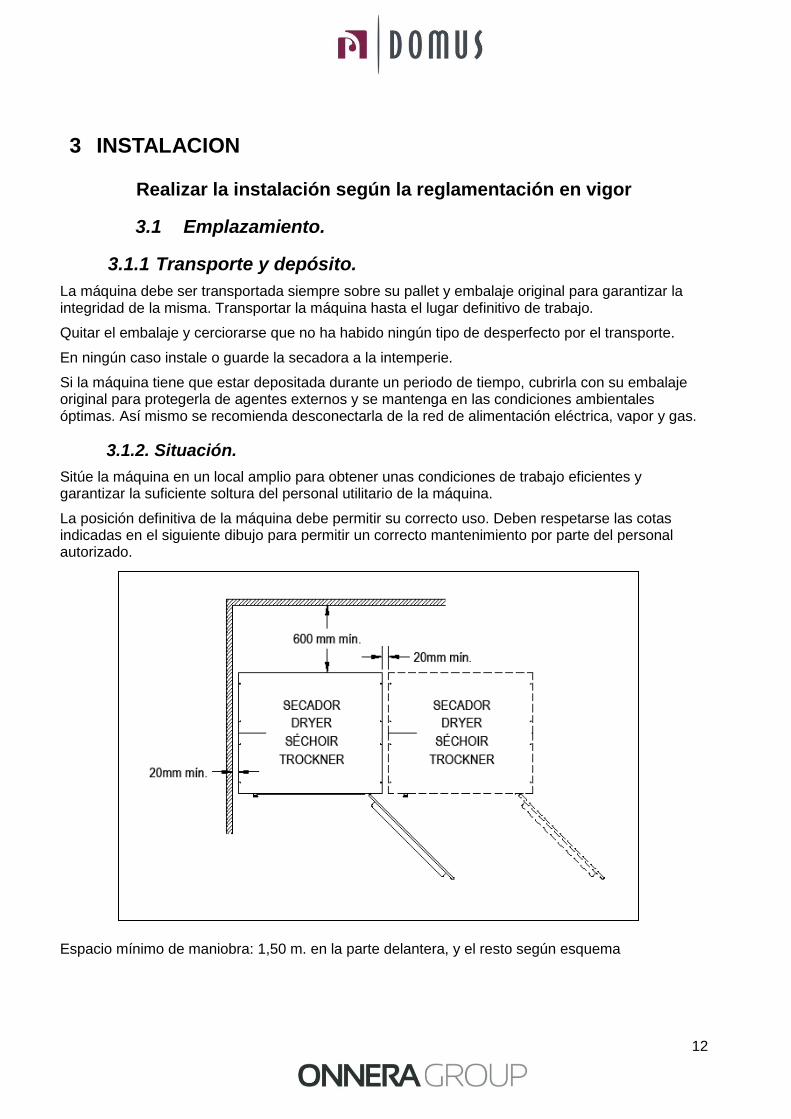
Sitúe la máquina en un local amplio para obtener unas condiciones de trabajo eficientes y garantizar la suficiente soltura del personal utilitario de la máquina.
La posición definitiva de la máquina debe permitir su correcto uso. Deben respetarse las cotas indicadas en el siguiente dibujo para permitir un correcto mantenimiento por parte del personal autorizado.
Espacio mínimo de maniobra: 1,50 m. en la parte delantera, y el resto según esquema

13
Una vez situada en su lugar de trabajo definitivo, extraer el pallet que está sujeto a la secadora por la parte posterior de la base con 2 tornillos. Guardarlo con el embalaje original para posibles y futuros desplazamientos. No empujar la máquina ni salvar obstáculos sin el pallet, la máquina corre peligro de deformación y mal funcionamiento.
El tambor no lleva anclajes para el transporte.
-SITUACION DE LOS TORNILLOS 1 Y 2 -DESTORNILLAR CON UNA LLAVE PLANA Nº 13

14
3.1.3. Nivelación.
-No anclar la máquina, simplemente disponerla en una superficie plana y nivelada. Colocar los cuatro pies regulables que se suministran y se encuentran en el interior de la máquina. Es importante un buen nivel de la base para un correcto funcionamiento.
Procedimiento:
-Regular los 4 pies de nivelación para asegurar la estabilidad y la horizontalidad de la máquina, comprobándola con un nivel. Una vez nivelados, fijar la tuerca con la ayuda de una llave inglesa.
-La altura máxima de ajuste en altura de los pies de nivelación es de 25mm.
3.2 Extracción de aire
3.2.1 Entrada de aire fresco Con el fin de conseguir un rendimiento óptimo y acortar al máximo los ciclos de secado es necesario asegurar que entra aire fresco desde el exterior de la habitación. Es aconsejable que la entrada de aire fresco esté situada detrás de la secadora.
15
La sección de entrada de aire fresco debe ser de cómo mínimo unas 4 veces superior a la sección del tubo de salida de aire. Nota: La sección de entrada de aire fresco equivale a la sección por la cual el aire puede fluir sin la resistencia debida a los barrotes o rejilla instalada en la misma entrada. Hay que tener en cuenta que a menudo los barrotes o rejilla pueden suponer gran parte de la sección de entrada.
3.2.2 Tubería de salida
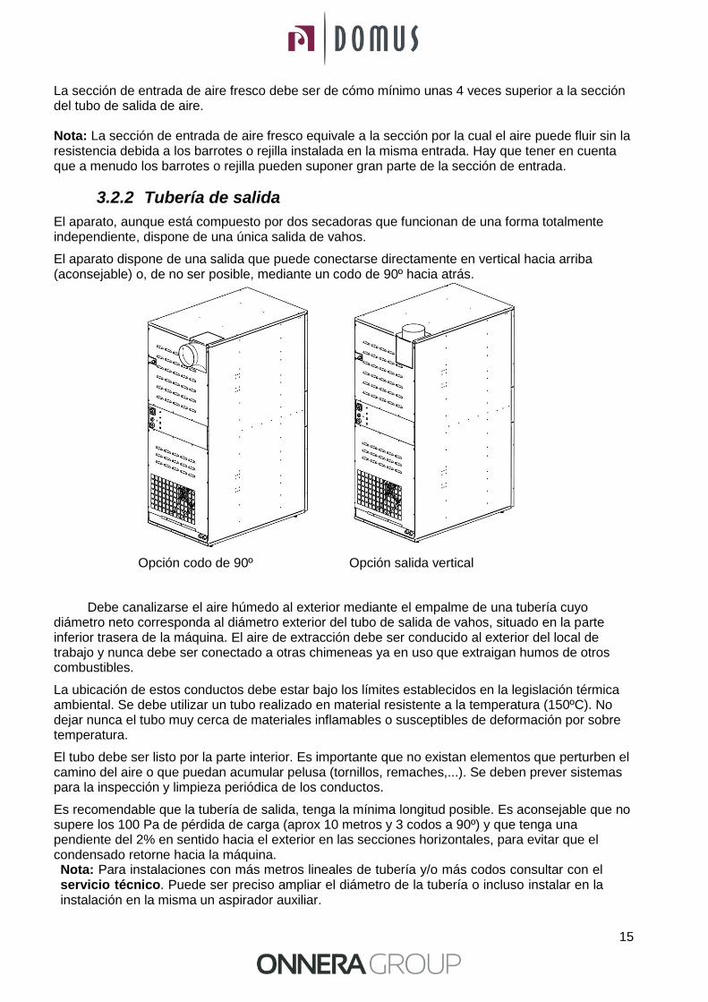
El aparato, aunque está compuesto por dos secadoras que funcionan de una forma totalmente independiente, dispone de una única salida de vahos.
El aparato dispone de una salida que puede conectarse directamente en vertical hacia arriba (aconsejable) o, de no ser posible, mediante un codo de 90º hacia atrás.
Opción codo de 90º Opción salida vertical
Debe canalizarse el aire húmedo al exterior mediante el empalme de una tubería cuyo diámetro neto corresponda al diámetro exterior del tubo de salida de vahos, situado en la parte inferior trasera de la máquina. El aire de extracción debe ser conducido al exterior del local de trabajo y nunca debe ser conectado a otras chimeneas ya en uso que extraigan humos de otros combustibles.
La ubicación de estos conductos debe estar bajo los límites establecidos en la legislación térmica ambiental. Se debe utilizar un tubo realizado en material resistente a la temperatura (150ºC). No dejar nunca el tubo muy cerca de materiales inflamables o susceptibles de deformación por sobre temperatura.
El tubo debe ser listo por la parte interior. Es importante que no existan elementos que perturben el camino del aire o que puedan acumular pelusa (tornillos, remaches,...). Se deben prever sistemas para la inspección y limpieza periódica de los conductos.
Es recomendable que la tubería de salida, tenga la mínima longitud posible. Es aconsejable que no supere los 100 Pa de pérdida de carga (aprox 10 metros y 3 codos a 90º) y que tenga una pendiente del 2% en sentido hacia el exterior en las secciones horizontales, para evitar que el condensado retorne hacia la máquina. Nota: Para instalaciones con más metros lineales de tubería y/o más codos consultar con el servicio técnico. Puede ser preciso ampliar el diámetro de la tubería o incluso instalar en la instalación en la misma un aspirador auxiliar.

16
Es preferible que cada máquina disponga de su salida de vahos independiente. Si no es posible:
Es OBLIGATORIO instalar un anti-retorno para cada una de las maquinas antes de llegar al tubo colector.
Siempre conexiones en Y. Nunca en T.
Aumentar la sección antes de la conexión de manera que la sección final sea la suma de las dos anteriores
IMPORTANTE: Debe preverse en la sala una/s entradas de aire fresco para permitir la entrada del volumen de aire que se debe extraer (ver apartado 3.2.1)
A continuación se incluye una tabla donde se puede consultar el diámetro equivalente necesario al conectar varias secadoras a una salida de vahos común así como el área mínima de entrada de aire fresco (ver apartado 3.2.1):
Número de secadoras 1 2 3 4 5 6 7 8 9 10
Diámetro del tubo de salida (mm)
200 300 350 400 450 500 500 560 600 630
Área mínima de entrada de aire al local (m²)
0,15 0,25 0,40 0,50 0,65 0,80 0,80 1,00 1,15 1,25
17
3.3 Conexión eléctrica
El aparato, aunque está compuesto por dos secadoras que funcionan de una forma totalmente independiente, dispone de una única conexión eléctrica.
Asegúrese de que las características de la alimentación disponible correspondan a las de su secadora, indicadas en la placa de identificación de la misma, y que la sección del cable y demás accesorios de la línea, puedan suministrar la potencia necesaria.
La máquina sale de fábrica con la instalación eléctrica completa, por lo tanto será suficiente quitar la tapa situada en la parte trasera de la secadora y unir cada uno de los bornes a las tres fases L1, L2, L3 y neutro N en los bornes de conexión o el interruptor general.
Es OBLIGATORIO intercalar un interruptor magneto térmico y un diferencial entre el conexionado y la red, la sensibilidad del diferencial deberá ser de 300mA. Una sensibilidad superior, por ejemplo 30 mA, usual en instalaciones domésticas, puede provocar anomalías de funcionamiento en la máquina.
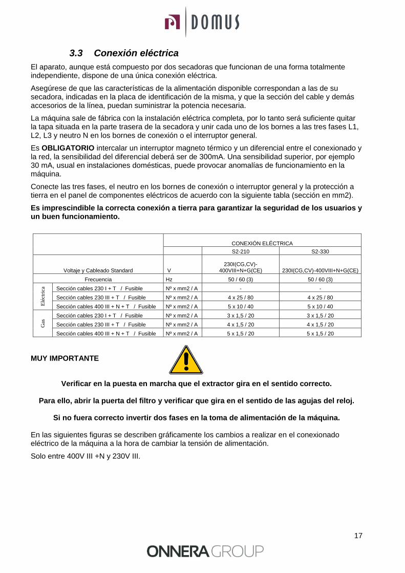
Conecte las tres fases, el neutro en los bornes de conexión o interruptor general y la protección a tierra en el panel de componentes eléctricos de acuerdo con la siguiente tabla (sección en mm2).
Es imprescindible la correcta conexión a tierra para garantizar la seguridad de los usuarios y un buen funcionamiento.
CONEXIÓN ELÉCTRICA
S2-210 S2-330
Voltaje y Cableado Standard V 230I(CG,CV)-
400VIII+N+G(CE) 230I(CG,CV)-400VIII+N+G(CE)
Frecuencia Hz 50 / 60 (3) 50 / 60 (3)
Elé
ctri
ca
Sección cables 230 I + T / Fusible Nº x mm2 / A - -
Sección cables 230 III + T / Fusible Nº x mm2 / A 4 x 25 / 80 4 x 25 / 80
Sección cables 400 III + N + T / Fusible Nº x mm2 / A 5 x 10 / 40 5 x 10 / 40
Gas
Sección cables 230 I + T / Fusible Nº x mm2 / A 3 x 1,5 / 20 3 x 1,5 / 20
Sección cables 230 III + T / Fusible Nº x mm2 / A 4 x 1,5 / 20 4 x 1,5 / 20
Sección cables 400 III + N + T / Fusible Nº x mm2 / A 5 x 1,5 / 20 5 x 1,5 / 20
MUY IMPORTANTE
Verificar en la puesta en marcha que el extractor gira en el sentido correcto.
Para ello, abrir la puerta del filtro y verificar que gira en el sentido de las agujas del reloj.
Si no fuera correcto invertir dos fases en la toma de alimentación de la máquina.
En las siguientes figuras se describen gráficamente los cambios a realizar en el conexionado eléctrico de la máquina a la hora de cambiar la tensión de alimentación.
Solo entre 400V III +N y 230V III.
18
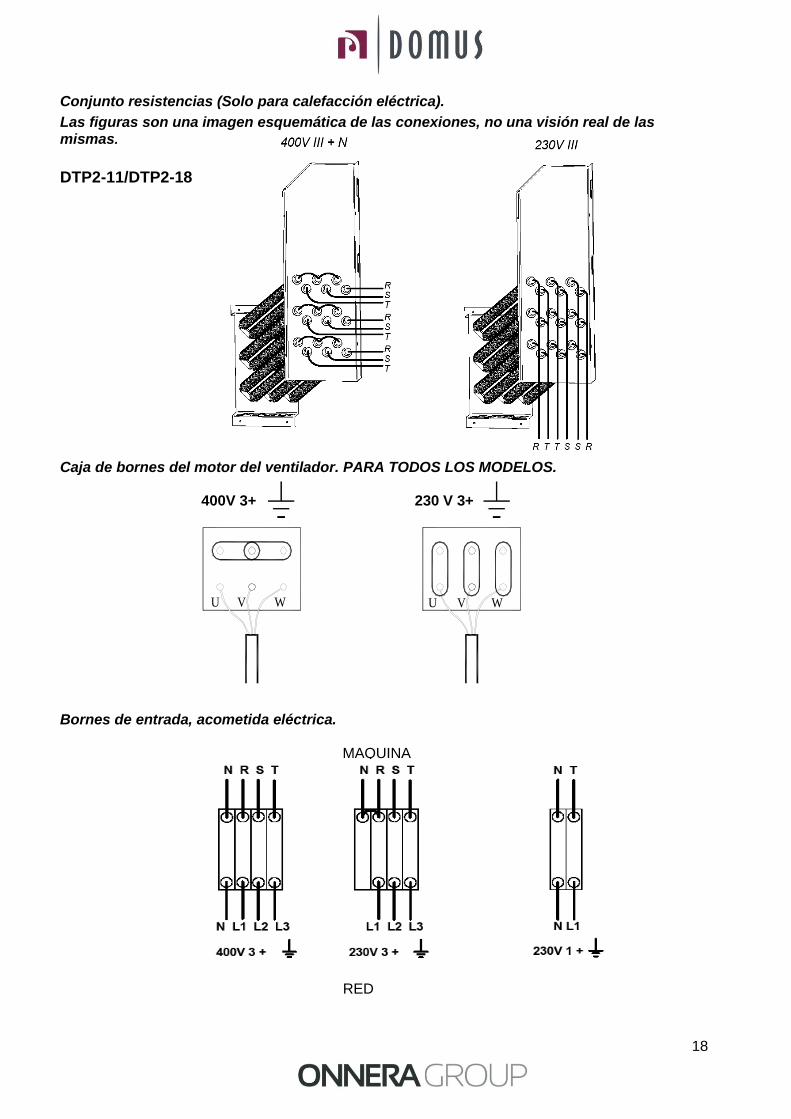
Conjunto resistencias (Solo para calefacción eléctrica).
Las figuras son una imagen esquemática de las conexiones, no una visión real de las mismas.
DTP2-11/DTP2-18 Caja de bornes del motor del ventilador. PARA TODOS LOS MODELOS.
400V 3+ 230 V 3+ Bornes de entrada, acometida eléctrica.
MAQUINA
RED
UWU V V W

19
3.4 Conexión a gas (sólo modelos a gas)
El aparato, aunque está compuesto por dos secadoras que funcionan de una forma totalmente independiente, dispone de una única entrada de gas.
Los secadores disponen de entrada a 1/2". Todos los modelos a gas están preparados para trabajar con gas propano (GLP) o gas natural (Ver placa de características del aparato).
Nota: La secadora está configurada para funcionar con una presión de quemador y un gas de acuerdo con el que viene en la placa de características. Compruebe que el tipo de gas y el valor de presión en el quemador corresponden con la placa de características. De no ser así, se deberá consultar con el proveedor.
No conectar un tubo de diámetro interior inferior al requerido por la máquina.
Instalar un regulador de presión (solo para GLP), una válvula manual y un filtro de gas delante de la máquina. Asegurarse de que la suciedad no entre en la válvula durante el conexionado.
Hacer el siguiente test de goteo:
Encender los quemadores. Con la ayuda de un cepillo, aplicar agua con jabón en las juntas de entrada de gas. Comprobar si se forman burbujas. Si es así, desmontar las válvulas, limpiarlas y volverlas a montar. No usar un jabón demasiado corrosivo.
También es posible realizar la prueba con algún producto especial destinado a ello.
Para gas propano GLP (G31) regulador de 37 mbar de presión de suministro y 4 Kg/h de caudal mínimo.
Para gas natural (G20) sin regulador, conectar directamente a la línea (20 mbar) e instalar una válvula manual.
La secadora de origen se puede entregar con inyectores de 4,2 mm regulada a una presión de quemador de 8 mbar para funcionar con gas natural o bien se puede entregar con inyectores de 2,3 mm regulada a una presión de quemador de 28,8 mbar para funcionar con gas propano.
La secadora dispone de inyectores de recambio y una nueva placa de características por si fuera necesario instalar el aparato para funcionar con un gas de grupo distinto, permitiendo poder instalar la máquina en muchos países con los principales combustibles
En la tabla siguiente se puede consultar para cada tipo de gas y en distintos países, el diámetro del inyector y la presión de quemador adecuados para funcionar correctamente.
DTP2-11 y DTP2-18 Potencia 2 x 12 kW
Gas Grupo País inyectores
Ø mm
Presión de suministro
mbar
Presión de quemador
mbar
Gas N
atu
ral
G20 2E (and 2H) mayoría de la UE 4.2 20 8
G20 2H HU 4.2 20 8
G20 2E+ FR, BE 3.4 20 18.9
G25 2E+ FR, BE 3.4 25 24.1
G25 2L NL 4.2 25 12
G25 2LL DE 4.2 20 12
G25.1 2S HU 4.2 25 13
GZ.35 2Ls PL 4.5 20 14
Gas B
uta
no
Pro
pano
G30 3B/P 30mbar mayoría de la UE 2.3 30 28.8
G30 3B/P AT, DE, LU, NL 2.3 50 27.7
G30 3B/P 36mbar PL 2.3 37 27.7
G30/G31 3+_28-30/37 BE, CZ, ES, IT, GB, IE, PT, FR 2.3 28-30/37 28.5/36.5
G31 3P LU 2.3 37 36.5
20
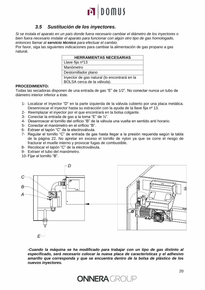
3.5 Sustitución de los inyectores.
Si se instala el aparato en un país donde fuera necesario cambiar el diámetro de los inyectores o bien fuera necesario instalar el aparato para funcionar con algún otro tipo de gas homologado, entonces llamar al servicio técnico para efectuar el cambio. Por favor, siga las siguientes indicaciones para cambiar la alimentación de gas propano a gas natural. PROCEDIMIENTO: Todas las secadoras disponen de una entrada de gas “E” de 1/2”. No conectar nunca un tubo de diámetro interior inferior a éste.
1- Localizar el Inyector “D” en la parte izquierda de la válvula cubierto por una placa metálica. Desenroscar el inyector hasta su extracción con la ayuda de la llave fija nº 13.
2- Reemplazar el inyector por el que encontrará en la bolsa colgante. 3- Conectar la entrada de gas a la toma “E” de ½”. 4- Desenroscar el tornillo del orificio “B” de la válvula una vuelta en sentido anti horario. 5- Conectar el manómetro en el orificio “B”. 6- Extraer el tapón “C” de la electroválvula. 7- Regular el tornillo “C” de entrada de gas hasta llegar a la presión requerida según la tabla
de la página 22. No apretar en exceso el tornillo de nylon ya que se corre el riesgo de fracturar el muelle interno y provocar fugas de combustible.
8- Recolocar el tapón “C” de la electroválvula. 9- Extraer el tubo del manómetro. 10- Fijar el tornillo “B”.
-Cuando la máquina se ha modificado para trabajar con un tipo de gas distinto al especificado, será necesario colocar la nueva placa de características y el adhesivo amarillo que corresponda y que se encuentra dentro de la bolsa de plástico de los nuevos inyectores.
HERRAMIENTAS NECESARIAS
Llave fija nº13
Manómetro
Destornillador plano
Inyector de gas natural (lo encontrará en la BOLSA cerca de la válvula).
21
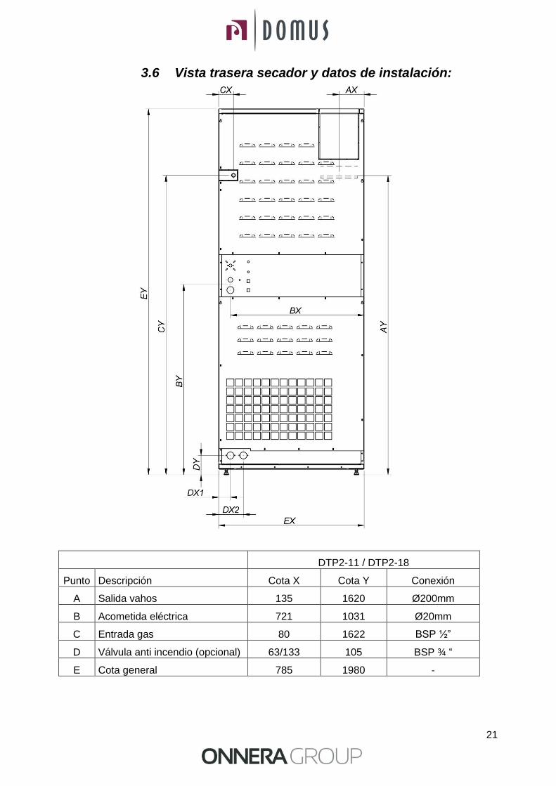
3.6 Vista trasera secador y datos de instalación:
DTP2-11 / DTP2-18
Punto Descripción Cota X Cota Y Conexión
A Salida vahos 135 1620 Ø200mm
B Acometida eléctrica 721 1031 Ø20mm
C Entrada gas 80 1622 BSP ½”
D Válvula anti incendio (opcional) 63/133 105 BSP ¾ “
E Cota general 785 1980 -
22
4 FUNCIONAMIENTO
4.1 Principio y descripción del funcionamiento:
La máquina seca las fibras pasando aire caliente a través de las fibras textiles. Este aire arrastra la humedad y la envía al exterior.
Pasos para un secado correcto:
Escoger el mismo tipo de fibra. No mezclar los diferentes tipos de fibras en un ciclo de secado.
Cargar el secador.
Abrir las alimentaciones a la maquina.
Escoger el programa de secado mediante el microprocesador
Apretar el botón de comienzo de ciclo START.
Al finalizar el ciclo retirar la carga.
!!! ATENCIÓN RETIRAR LA CARGA SIN REALIZAR EL COOL-DOWN (ENFRIAMIENTO PROGRESIVO) PUEDE PRODUCIR QUEMADURAS!!!
23
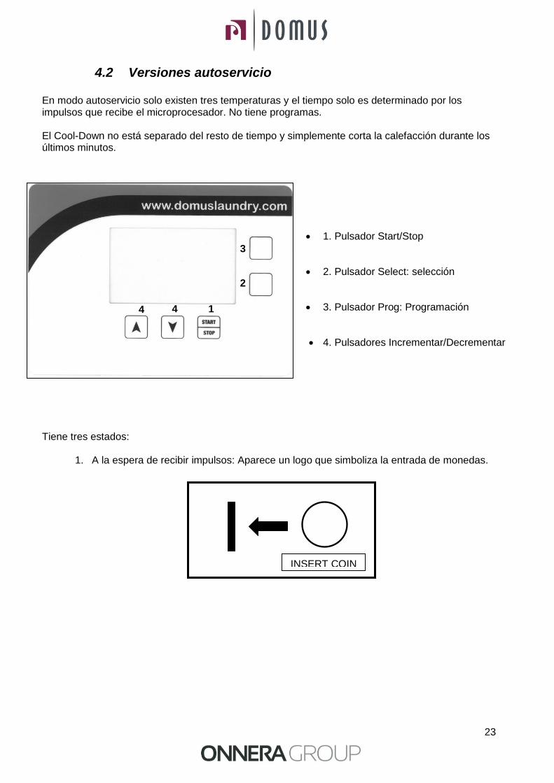
4.2 Versiones autoservicio En modo autoservicio solo existen tres temperaturas y el tiempo solo es determinado por los impulsos que recibe el microprocesador. No tiene programas. El Cool-Down no está separado del resto de tiempo y simplemente corta la calefacción durante los últimos minutos.
1. Pulsador Start/Stop
2. Pulsador Select: selección
3. Pulsador Prog: Programación
4. Pulsadores Incrementar/Decrementar Tiene tres estados:
1. A la espera de recibir impulsos: Aparece un logo que simboliza la entrada de monedas.
INSERT COIN
2
1 4
3
4

24
1. Cuando la secadora está en STANDBY, se puede visualizar el tiempo restante y el reloj
no parpadea y además aparece el símbolo de pulsar start. También se puede visualizar
el nivel de temperatura que el usuario ha seleccionado para trabajar (bajo, medio o alto)
Al pulsar les flechas arriba/abajo se moverá la temperatura seleccionada.
2. Una vez pulsado Start se pondrá en funcionamiento. Se puede ver el tiempo restante y el reloj parpadea. En todo momento se puede seleccionar un nivel de temperatura distinto pulsando las flechas arriba / abajo.
Cuando se agote el tiempo, sonará el buzzer, aparecerá END.
4.2.1 Versión dos monederos / central de pago En estas dos versiones el tiempo se verá incrementado en cada uno de los displays correspondientes a cada secadora (arriba/abajo) y los pulsos procederán directamente del monedero correspondiente o de la central de pago.
4.2.2 Versión con un solo monedero (con selector) En esta versión el aparato dispone de un solo monedero y un selector con pulsadores con leds integrados para poder escoger a cuál de las dos secadoras se quiere incrementar el tiempo.
Todas las monedas o fichas se introducen en el mismo monedero. A continuación se debe seleccionar en el selector secadora de arriba o secadora de abajo pulsando el botón correspondiente. Por último se debe pulsar el botón ENTER para hacer efectivo el incremento de tiempo a la secadora seleccionada.

25
Estados del selector 1. En espera de incrementar saldo. Los leds de los tres pulsadores están parpadeando. 2. Con saldo a la espera de selección secadora. Los dos leds de los pulsadores SELECT
parpadean de forma alternada. El led ENTER está apagado 3. En espera de confirmación. El led ENTER está parpadeando. Los dos leds de los pulsadores
SELECT están apagados. 4. Incrementando tiempo: El led del pulsador SELECT correspondiente a la secadora que
incrementa tiempo parpadea. El otro led del pulsador SELECT y el led del pulsador ENTER están apagados..
1. Selector Secadora superior
2. Selector Secadora inferior
3. Enter
4.2.3 Edición de parámetros
MENÚ DE USUARIO
En el momento que la secadora recibe tensión, se dispone de 3 minutos para poder acceder a
introducir una clave (PASSWORD) pulsando a la vez las teclas PROG y SELECT. Una vez transcurridos
los 3 minutos, ya no será posible poder introducir ninguna clave, el sistema hará caso omiso a la pulsación
de dichas teclas. De esta manera queda totalmente blindado el acceso a poder introducir una clave y a
que algún usuario acceda a un menú que no es propio del usuario.
Por lo tanto, pulsar a la vez las teclas PROG y SELECT y aparecerá en el display:
PASSWORD
* * * *
2
3
1
26
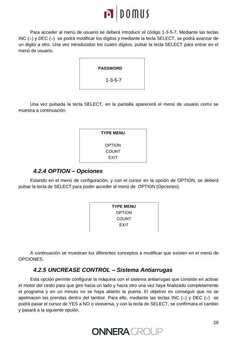
Para acceder al menú de usuario se deberá introducir el código 1-3-5-7. Mediante las teclas
INC () y DEC () se podrá modificar los dígitos y mediante la tecla SELECT, se podrá avanzar de
un digito a otro. Una vez introducidos los cuatro dígitos, pulsar la tecla SELECT para entrar en el
menú de usuario.
PASSWORD
1-3-5-7
Una vez pulsada la tecla SELECT, en la pantalla aparecerá el menú de usuario como se
muestra a continuación.
TYPE MENU
OPTION
COUNT
EXIT
4.2.4 OPTION – Opciones
Estando en el menú de configuración, y con el cursor en la opción de OPTION, se deberá
pulsar la tecla de SELECT para poder acceder al menú de OPTION (Opciones).
A continuación se muestran los diferentes conceptos a modificar que existen en el menú de
OPCIONES.
4.2.5 UNCREASE CONTROL – Sistema Antiarrugas
Esta opción permite configurar la máquina con el sistema antiarrugas que consiste en activar
el motor del cesto para que gire hacia un lado y hacia otro una vez haya finalizado completamente
el programa y en un minuto no se haya abierto la puerta. El objetivo es conseguir que no se
apelmacen las prendas dentro del tambor. Para ello, mediante las teclas INC () y DEC () se
podrá pasar el cursor de YES a NO o viceversa, y con la tecla de SELECT, se confirmara el cambio
y pasará a la siguiente opción.
TYPE MENU
OPTION
COUNT
EXIT

27
4.2.6 PULSE TIME – Tiempo de impulso
Este parámetro define el tiempo concedido para cada impulso y viene dado en segundos. El
valor de fábrica es de 300 segundos. Para ello, mediante las teclas INC () y DEC () se podrá
modificar el tiempo con saltos de 10 segundos y con la tecla de SELECT, se confirmará el cambio.
4.2.7 PULSES REQUIRED – Mínimos pulsos requeridos
Este parámetro define la cantidad mínima de pulsos que debe recibir el programador para
aumentar el saldo. Cuando el programador reciba dicha cantidad de pulsos el saldo se verá
aumentado con el tiempo correspondiente a la cantidad de pulsos recibidos teniendo en cuenta el
valor de tiempo introducido en el parámetro PULSE TIME. El valor de fábrica es de 1, con lo cual si
no se modifica este valor, el programador aumentará el saldo con cada pulso recibido. Para ello,
mediante las teclas INC () y DEC () se podrá modificar el valor y con la tecla de SELECT, se
confirmará el cambio.
PULSES REQUIRED, combinado con PULSE TIME, sirve para introducir un precio mínimo de
funcionamiento. Por ejemplo, en el caso de un aparato que funcione en euros donde 50 céntimos
equivale a un pulso y se desea poner un precio de 3 euros para un secado de 40 minutos.
Entonces se sabe que 3 euros son 6 pulsos, por lo tanto, la cantidad mínima de pulsos deberá ser
6 y el tiempo de pulso deberá ser de 40/6 = 6,666 minutos = 400 segundos. Así pues, se deberá
introducir PULSE TIME 400 y PULSES REQUIRED 6. Mientras el programador no reciba los 6
pulsos, no aumentará saldo, una vez recibidos los 6 pulsos, entonces aumentará los 400 x 6
segundos equivalentes a 40 minutos.
UNCREASE CONTROL YES / NO
PULSE TIME
300
PULSES REQUIRED
01
28
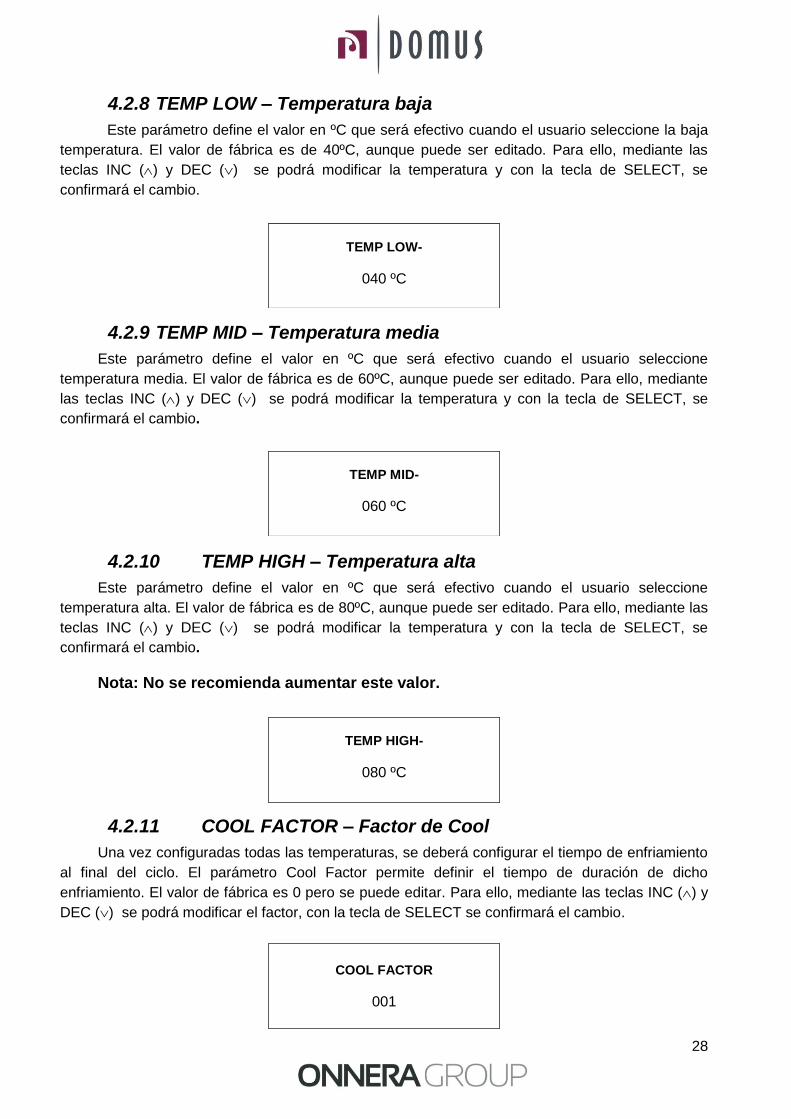
4.2.8 TEMP LOW – Temperatura baja
Este parámetro define el valor en ºC que será efectivo cuando el usuario seleccione la baja
temperatura. El valor de fábrica es de 40ºC, aunque puede ser editado. Para ello, mediante las
teclas INC () y DEC () se podrá modificar la temperatura y con la tecla de SELECT, se
confirmará el cambio.
4.2.9 TEMP MID – Temperatura media
Este parámetro define el valor en ºC que será efectivo cuando el usuario seleccione
temperatura media. El valor de fábrica es de 60ºC, aunque puede ser editado. Para ello, mediante
las teclas INC () y DEC () se podrá modificar la temperatura y con la tecla de SELECT, se
confirmará el cambio.
4.2.10 TEMP HIGH – Temperatura alta
Este parámetro define el valor en ºC que será efectivo cuando el usuario seleccione
temperatura alta. El valor de fábrica es de 80ºC, aunque puede ser editado. Para ello, mediante las
teclas INC () y DEC () se podrá modificar la temperatura y con la tecla de SELECT, se
confirmará el cambio.
Nota: No se recomienda aumentar este valor.
4.2.11 COOL FACTOR – Factor de Cool
Una vez configuradas todas las temperaturas, se deberá configurar el tiempo de enfriamiento
al final del ciclo. El parámetro Cool Factor permite definir el tiempo de duración de dicho
enfriamiento. El valor de fábrica es 0 pero se puede editar. Para ello, mediante las teclas INC () y
DEC () se podrá modificar el factor, con la tecla de SELECT se confirmará el cambio.
TEMP LOW-
040 ºC
TEMP MID-
060 ºC
TEMP HIGH-
080 ºC
COOL FACTOR
001
29
IMPORTANTE: LOS MINUTOS DE COOLDOWN ESTAN INTEGRADOS DENTRO
DEL TIEMPO DE AUTO-SERVICIO
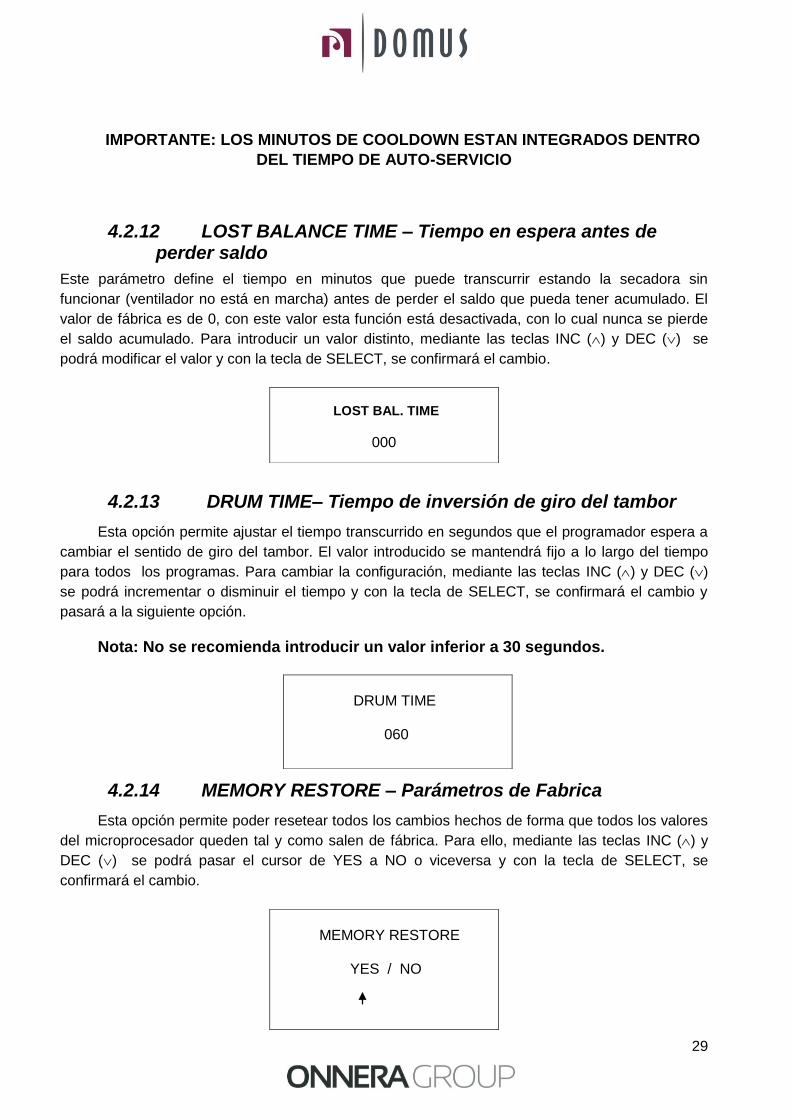
4.2.12 LOST BALANCE TIME – Tiempo en espera antes de perder saldo
Este parámetro define el tiempo en minutos que puede transcurrir estando la secadora sin
funcionar (ventilador no está en marcha) antes de perder el saldo que pueda tener acumulado. El
valor de fábrica es de 0, con este valor esta función está desactivada, con lo cual nunca se pierde
el saldo acumulado. Para introducir un valor distinto, mediante las teclas INC () y DEC () se
podrá modificar el valor y con la tecla de SELECT, se confirmará el cambio.
4.2.13 DRUM TIME– Tiempo de inversión de giro del tambor
Esta opción permite ajustar el tiempo transcurrido en segundos que el programador espera a
cambiar el sentido de giro del tambor. El valor introducido se mantendrá fijo a lo largo del tiempo
para todos los programas. Para cambiar la configuración, mediante las teclas INC () y DEC ()
se podrá incrementar o disminuir el tiempo y con la tecla de SELECT, se confirmará el cambio y
pasará a la siguiente opción.
Nota: No se recomienda introducir un valor inferior a 30 segundos.
4.2.14 MEMORY RESTORE – Parámetros de Fabrica
Esta opción permite poder resetear todos los cambios hechos de forma que todos los valores
del microprocesador queden tal y como salen de fábrica. Para ello, mediante las teclas INC () y
DEC () se podrá pasar el cursor de YES a NO o viceversa y con la tecla de SELECT, se
confirmará el cambio.
LOST BAL. TIME
000
DRUM TIME 060
MEMORY RESTORE YES / NO
30
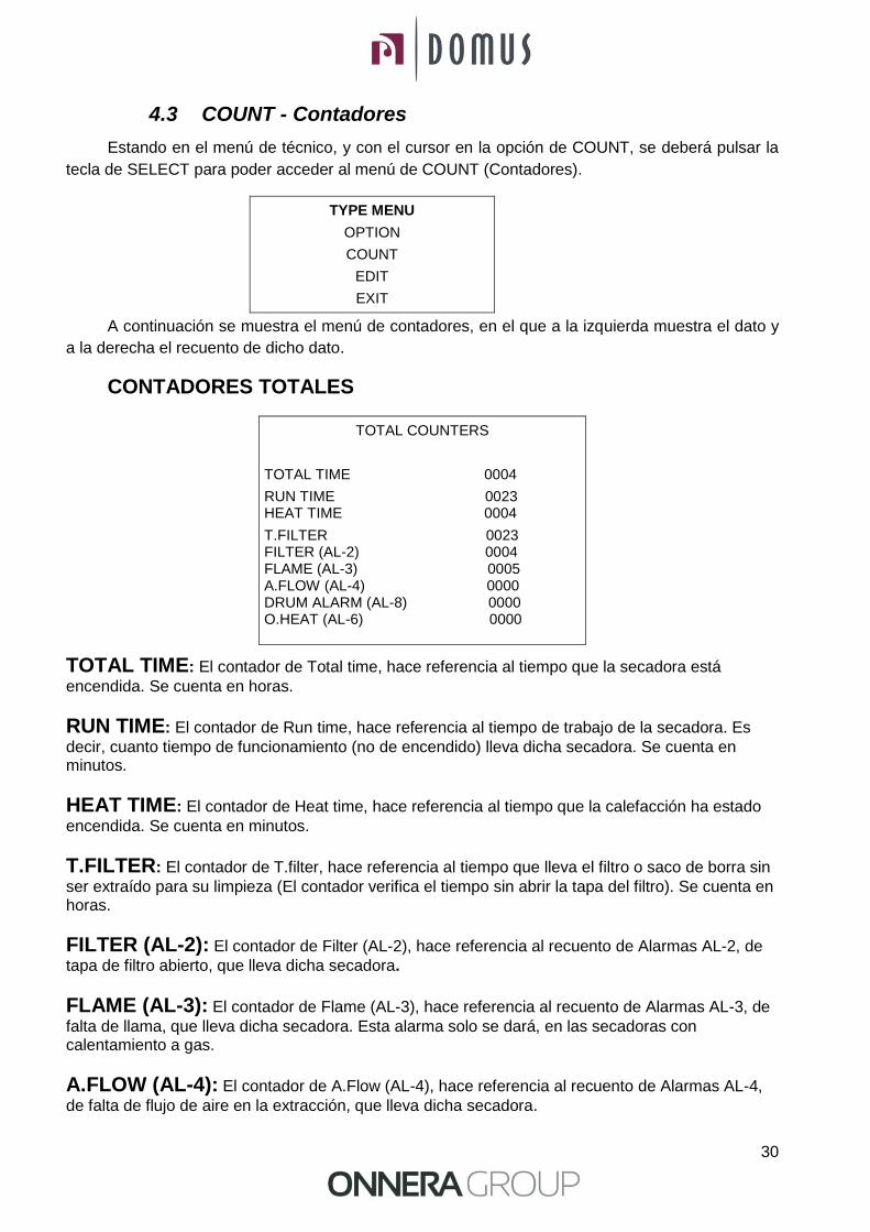
4.3 COUNT - Contadores
Estando en el menú de técnico, y con el cursor en la opción de COUNT, se deberá pulsar la
tecla de SELECT para poder acceder al menú de COUNT (Contadores).
TYPE MENU
OPTION
COUNT
EDIT
EXIT
A continuación se muestra el menú de contadores, en el que a la izquierda muestra el dato y
a la derecha el recuento de dicho dato.
CONTADORES TOTALES
TOTAL TIME: El contador de Total time, hace referencia al tiempo que la secadora está
encendida. Se cuenta en horas.
RUN TIME: El contador de Run time, hace referencia al tiempo de trabajo de la secadora. Es
decir, cuanto tiempo de funcionamiento (no de encendido) lleva dicha secadora. Se cuenta en minutos.
HEAT TIME: El contador de Heat time, hace referencia al tiempo que la calefacción ha estado
encendida. Se cuenta en minutos.
T.FILTER: El contador de T.filter, hace referencia al tiempo que lleva el filtro o saco de borra sin
ser extraído para su limpieza (El contador verifica el tiempo sin abrir la tapa del filtro). Se cuenta en horas.
FILTER (AL-2): El contador de Filter (AL-2), hace referencia al recuento de Alarmas AL-2, de
tapa de filtro abierto, que lleva dicha secadora.
FLAME (AL-3): El contador de Flame (AL-3), hace referencia al recuento de Alarmas AL-3, de
falta de llama, que lleva dicha secadora. Esta alarma solo se dará, en las secadoras con calentamiento a gas.
A.FLOW (AL-4): El contador de A.Flow (AL-4), hace referencia al recuento de Alarmas AL-4,
de falta de flujo de aire en la extracción, que lleva dicha secadora.
TOTAL COUNTERS
TOTAL TIME 0004
RUN TIME 0023 HEAT TIME 0004
T.FILTER 0023 FILTER (AL-2) 0004 FLAME (AL-3) 0005 A.FLOW (AL-4) 0000 DRUM ALARM (AL-8) 0000 O.HEAT (AL-6) 0000
31
DRUM ALARM (AL-8): El contador de Drum Alarm, hace referencia al recuento de Alarmas
de transmisión, que lleva dicha secadora. Esta alarma solo se dará, en las secadoras con transmisión mediante correa.
O.HEAT (AL-6): El contador de O. Heat (AL-6), hace referencia al recuento de Alarmas AL-6,
donde el termostato de seguridad ha actuado cortando el circuito de calefacción.
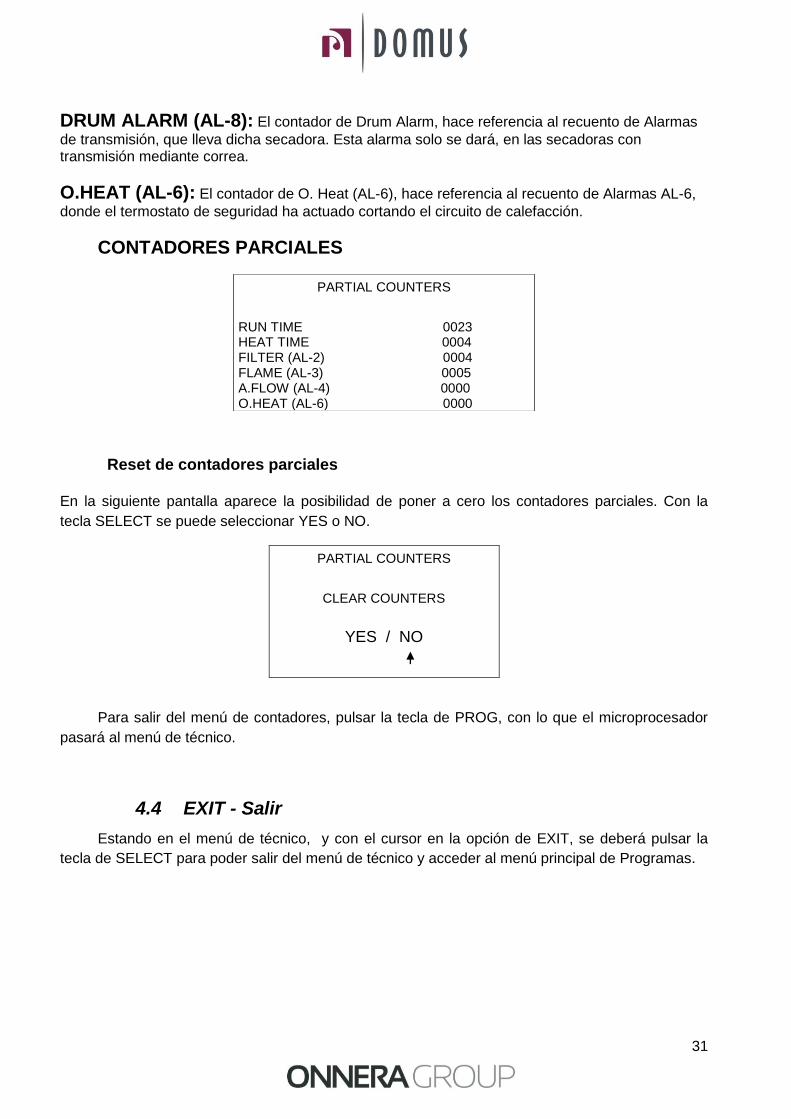
CONTADORES PARCIALES
Reset de contadores parciales
En la siguiente pantalla aparece la posibilidad de poner a cero los contadores parciales. Con la
tecla SELECT se puede seleccionar YES o NO.
Para salir del menú de contadores, pulsar la tecla de PROG, con lo que el microprocesador
pasará al menú de técnico.
4.4 EXIT - Salir
Estando en el menú de técnico, y con el cursor en la opción de EXIT, se deberá pulsar la
tecla de SELECT para poder salir del menú de técnico y acceder al menú principal de Programas.
PARTIAL COUNTERS
RUN TIME 0023 HEAT TIME 0004 FILTER (AL-2) 0004 FLAME (AL-3) 0005 A.FLOW (AL-4) 0000 O.HEAT (AL-6) 0000
PARTIAL COUNTERS
CLEAR COUNTERS
YES / NO
32
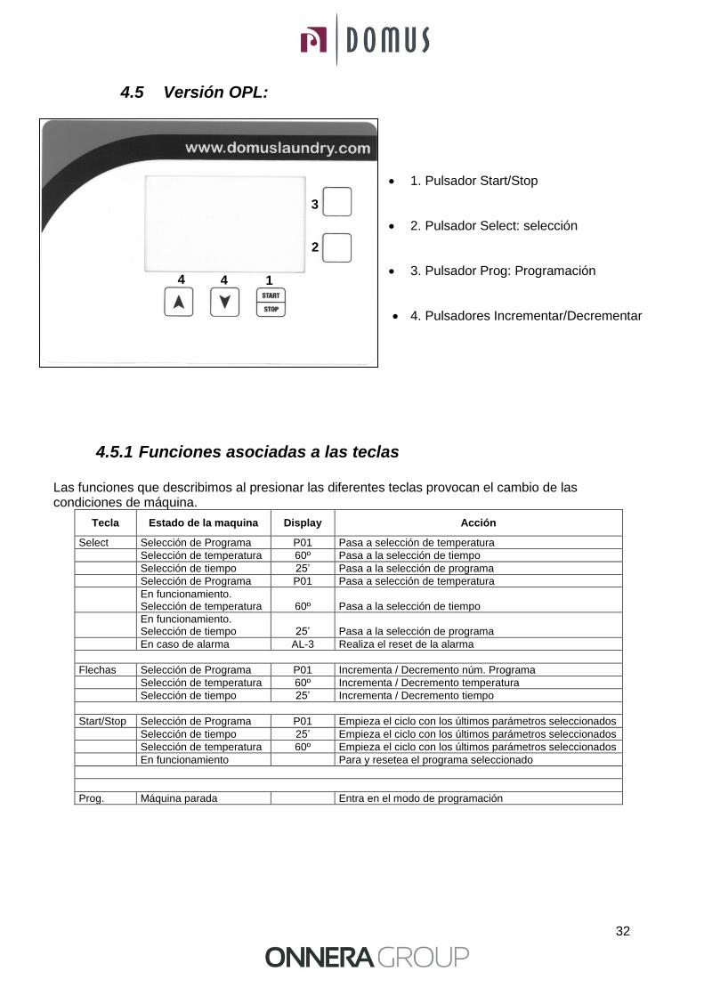
4.5 Versión OPL:
1. Pulsador Start/Stop
2. Pulsador Select: selección
3. Pulsador Prog: Programación
4. Pulsadores Incrementar/Decrementar
4.5.1 Funciones asociadas a las teclas Las funciones que describimos al presionar las diferentes teclas provocan el cambio de las condiciones de máquina.
Tecla Estado de la maquina Display Acción
Select Selección de Programa P01 Pasa a selección de temperatura
Selección de temperatura 60º Pasa a la selección de tiempo
Selección de tiempo 25’ Pasa a la selección de programa
Selección de Programa P01 Pasa a selección de temperatura
En funcionamiento. Selección de temperatura 60º Pasa a la selección de tiempo
En funcionamiento. Selección de tiempo 25’ Pasa a la selección de programa
En caso de alarma AL-3 Realiza el reset de la alarma
Flechas Selección de Programa P01 Incrementa / Decremento núm. Programa
Selección de temperatura 60º Incrementa / Decremento temperatura
Selección de tiempo 25’ Incrementa / Decremento tiempo
Start/Stop Selección de Programa P01 Empieza el ciclo con los últimos parámetros seleccionados
Selección de tiempo 25’ Empieza el ciclo con los últimos parámetros seleccionados
Selección de temperatura 60º Empieza el ciclo con los últimos parámetros seleccionados
En funcionamiento Para y resetea el programa seleccionado
Prog. Máquina parada Entra en el modo de programación
2
1 4
3
4

33
4.5.2 Información visualizada en el display
El display muestra diversos tipos de informaciones, como el número de programa el tiempo restante y la temperatura de consigna. La información puede variar según el estado de la máquina en aquel momento.
Cuando la máquina está en funcionamiento el símbolo del reloj es intermitente.
Cuando la calefacción esta en ON aparece una flecha al lado del termómetro indicando hacia arriba.
La tabla siguiente muestra otras posibilidades de informaciones y en las condiciones que se muestran.
Display Estado de la maquina Comentarios
MP / En el encendido (2s) Muestra la versión de software
END Finalización / Antiarrugas Finalización de ciclo / Fase antiarrugas (2)
AL-X Alarma Muestra una de las alarmas ver apartado 5
(2) La Fase Fin / Antiarrugas dura un máximo de 99 minutos. Durante este tiempo cada 3 minutos realiza una alarma sonora para recordar que el ciclo ha finalizado. Al cabo de los 99 minutos la máquina vuelve a la situación: En espera.
4.5.3 Cómo realizar un secado utilizando un programa estándar Cuando la máquina está en ESPERA, pulsar las flechas para seleccionar el núm. de programa deseado. Cuando el display visualiza el programa deseado pulsar START/STOP, y seguidamente se pone en marcha el programa deseado.
4.5.4 Cómo realizar un secado utilizando los valores definidos por el usuario
Cuando la máquina está en ESPERA, pulsar la tecla SELECT hasta que se nos visualiza en intermitencia 60º (Temperatura de Secado) y modificarla con las flechas. Pulsar de nuevo SELECT para visualizar en intermitencia el tiempo de secado, 25’ y con las flechas modificar el tiempo. Pulsar START/STOP para activar la ejecución del secado. Estos valores se pueden modificar también con la máquina en funcionamiento.
34
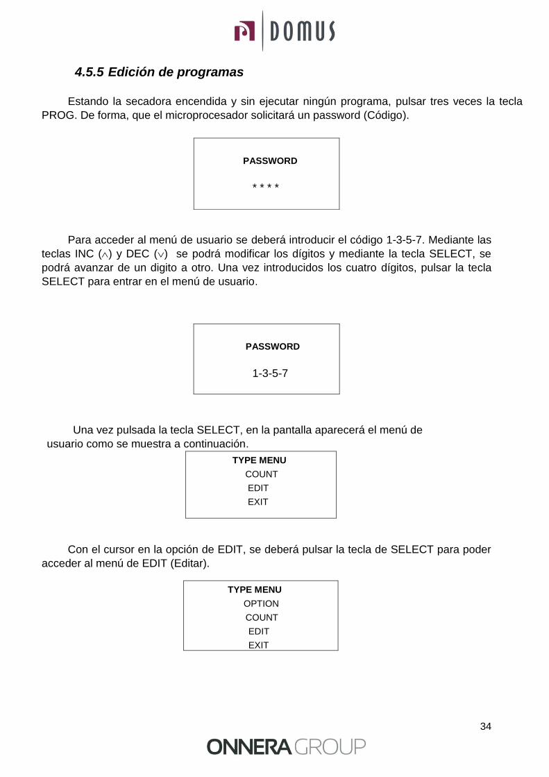
4.5.5 Edición de programas
Estando la secadora encendida y sin ejecutar ningún programa, pulsar tres veces la tecla
PROG. De forma, que el microprocesador solicitará un password (Código).
Para acceder al menú de usuario se deberá introducir el código 1-3-5-7. Mediante las
teclas INC () y DEC () se podrá modificar los dígitos y mediante la tecla SELECT, se
podrá avanzar de un digito a otro. Una vez introducidos los cuatro dígitos, pulsar la tecla
SELECT para entrar en el menú de usuario.
Una vez pulsada la tecla SELECT, en la pantalla aparecerá el menú de
usuario como se muestra a continuación.
TYPE MENU
COUNT
EDIT
EXIT
Con el cursor en la opción de EDIT, se deberá pulsar la tecla de SELECT para poder
acceder al menú de EDIT (Editar).
TYPE MENU
OPTION
COUNT
EDIT
EXIT
PASSWORD
* * * *
PASSWORD
1-3-5-7
35
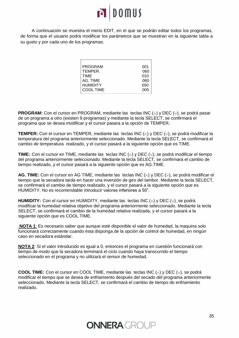
A continuación se muestra el menú EDIT, en el que se podrán editar todos los programas,
de forma que el usuario podrá modificar los parámetros que se muestran en la siguiente tabla a
su gusto y por cada uno de los programas.
PROGRAM: Con el cursor en PROGRAM, mediante las teclas INC () y DEC (), se podrá pasar de un programa a otro (existen 9 programas) y mediante la tecla SELECT, se confirmará el programa que se desea modificar y el cursor pasara a la opción de TEMPER.
TEMPER: Con el cursor en TEMPER, mediante las teclas INC () y DEC (), se podrá modificar la temperatura del programa anteriormente seleccionado. Mediante la tecla SELECT, se confirmará el cambio de temperatura realizado, y el cursor pasará a la siguiente opción que es TIME.
TIME: Con el cursor en TIME, mediante las teclas INC () y DEC (), se podrá modificar el tiempo del programa anteriormente seleccionado. Mediante la tecla SELECT, se confirmará el cambio de tiempo realizado, y el cursor pasará a la siguiente opción que es AG.TIME.
AG. TIME: Con el cursor en AG TIME, mediante las teclas INC () y DEC (), se podrá modificar el tiempo que la secadora tarda en hacer una inversión de giro del tambor. Mediante la tecla SELECT, se confirmará el cambio de tiempo realizado, y el cursor pasará a la siguiente opción que es HUMIDITY. No es recomendable introducir valores inferiores a 50”.
HUMIDITY: Con el cursor en HUMIDITY, mediante las teclas INC () y DEC (), se podrá modificar la humedad relativa objetivo del programa anteriormente seleccionado. Mediante la tecla SELECT, se confirmará el cambio de la humedad relativa realizada, y el cursor pasará a la siguiente opción que es COOL TIME. NOTA 1: Es necesario saber que aunque esté disponible el valor de humedad, la maquina solo funcionará correctamente cuando ésta disponga de la opción de control de humedad, en ningún caso en secadora estándar. NOTA 2: Si el valor introducido es igual a 0, entonces el programa en cuestión funcionará con tiempo de modo que la secadora terminará el ciclo cuando haya transcurrido el tiempo seleccionado en el programa y no utilizará el sensor de humedad.
COOL TIME: Con el cursor en COOL TIME, mediante las teclas INC () y DEC (), se podrá modificar el tiempo que se desea de enfriamiento después del secado del programa anteriormente seleccionado. Mediante la tecla SELECT, se confirmará el cambio de tiempo de enfriamiento realizado.
PROGRAM 001 TEMPER. 060 TIME 010 AG. TIME 060 HUMIDITY 050 COOL TIME 005

36
Para salir del menú de contadores, pulsar la tecla de PROG estando en el menú de usuario, y con el cursor en la opción de EXIT, se deberá pulsar la tecla de SELECT para poder salir del menú de técnico y acceder al menú principal de Programas.
A continuación se muestra una tabla con los parámetros que por defecto configuran cada programa.
5 ALARMAS Y AVISOS Las alarmas de apertura puerta o apertura filtro, comportan una pausa del programa en curso, al desaparecer las condiciones de alarma, es posible reanudar el secado en el momento que se cierra la alarma. Las otras alarmas suponen un paro del programa y la activación del aviso acústico. Este aviso se para pulsando SELECT o anulando la causa de la alarma. En la siguiente tabla hay una lista de las alarmas y sus posibles soluciones.
Alarma Significado Posibles soluciones
AL-1 Puerta abierta * Cerrar la puerta.
AL-2 Tapa filtro abierta * Cerrar la tapa.
AL-3 Falta de llama * Comprobar llave suministro gas abierta. * Comprobar que la presión sea la correcta. Ver 3.5.
AL-4 Falta de depresión o flujo de aire insuficiente
* Verificar que el conducto de salida está libre, comprobar que no tiene un recorrido excesivo. * Verificar que el filtro esté limpio de pelusa. * Verificar que la turbina del ventilador está limpia de pelusa.
AL-5 Sobrecarga motor-ventilador
* Verificar que el conducto de salida está correctamente conectado, que no tiene salida libre.
AL-6 Sobre temperatura * Verificar que el flujo de aire es correcto. * Verificar que la presión de gas es correcta.
AL-7 Filtro sucio * Limpiar el filtro. * Limpiar el filtro con mayor regularidad, no llegar hasta este punto. En modelos autoservicio nunca aparece esta alarma
AL-9 Alarma sonda * Problema con las sondas de temperatura y/o humedad. Contactar con su Servicio de Asistencia Técnica.
Si cualquiera de las alarmas anteriores persiste, consulte con su Servicio de Asistencia Técnica. Siempre use el número de serie de la máquina para sus consultas.
PROGRAMA UTILIDAD
RECOMENDADA SECADO TIEMPO DE
GIRO
Min ºC %H.R.
1 TOALLAS 30 80 25 70
2 ALGODÓN 1 35 75 25 70
3 ALGODÓN 2 40 65 30 70
4 SINTETICO 20 60 30 70
5 DELICADO 25 45 30 70
6 INTENSIVO 1 20 75 30 70
7 INTENSIVO 2 30 75 30 70
8 EXTRA 1 15 90 20 30
9 EXTRA 2 20 90 15 30
37
6 MANTENIMIENTO
El mayor enemigo de la secadora es la pelusa o borra de la ropa. La máquina en general y sus partes deben permanecer libres de pelusa que puedan dificultar su funcionamiento.
Debe realizarse una aspiración y limpieza general de la máquina una vez al mes.
El rendimiento de la máquina viene condicionado en buena medida por la limpieza de sus componentes.
El accionamiento de la máquina no necesita ningún tipo de mantenimiento. El engrase en los rodamiento y el moto reductor es permanente para toda la vida de la maquina.
6.1 Filtro borras:
Es aconsejable cada 10 horas de funcionamiento limpiar el filtro de borras para obtener el máximo rendimiento en la máquina.
Para limpiar el filtro, se debe proceder como se explica en el apartado 2.1
6.2 Batería calefactora:
En el caso de calefacción eléctrica una vez cada dos meses limpiar la borra y polvo acumulado encima de la batería para evitar riesgos.
6.3 Extractor de aire: Verificar una vez al mes la limpieza de los álabes del extractor. La acumulación de borra en esta parte puede causar un mal funcionamiento del aparato y averías.

38
7 PROBLEMAS Y SOLUCIONES
7.1 Tabla Problema-Causa-Solución
Problema Causa Solución
El secador no arranca
Tiempo a 0 Seleccionar un tiempo correcto
Puerta abierta Cerrar la puerta
Tapa abierta Cerrar la tapa filtro
Micro tapa /puerta defectuoso
Cambiar el micro-tapa o puerta
Pulsador de emergencia Girar ¼ de vuelta para desconectarlo
Sin potencia eléctrica
Verificar interruptor general en ON
Verificar el buen estado de los fusibles
Verificar Voltaje de la red correcto
El secador no calienta El secador no calienta
Temporizador en Cool-Down
Aumentar el tiempo seleccionado
La calefacción no recibe señal ON
Verificar termostato / Placa electrónica de control
Verificar termostato de seguridad (1)
Alarma de gas Realizar un reset de la alarma (2)
Temporizador en Cool-Down
Aumentar el tiempo seleccionado
El secador no seca lo suficiente
Tiempo de ciclo insuficiente
Aumentar el tiempo de ciclo
Flujo de aire insuficiente
Limpiar el filtro de borra
Verificar que el conducto de salida limpio y no esté bloqueado
Limpiar álabes del ventilador-extractor
Conducto de salida demasiado largo
Verificar que la sala tenga las entradas de aire fresco suficientes.
(1) Para resetear el termostato de seguridad, quitar el botón de plástico negro y pulsar el botón en la parte posterior de la maquina, volver a tapar. Si se repite el problema, contactar con nuestro servicio Post-venda.
(2) Para resetear la alarma gas, pulsar el botón negro en la parte posterior de la máquina. Si se
repite el problema, contactar con nuestro servicio Post-venta.
En cualquier otro caso, no dude en ponerse en contacto con nuestro servicio Post-venta.
39
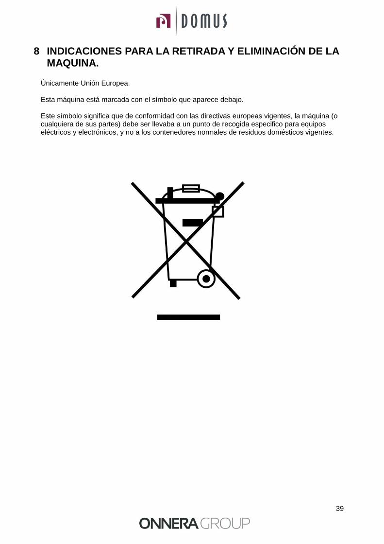
8 INDICACIONES PARA LA RETIRADA Y ELIMINACIÓN DE LA MAQUINA.
Únicamente Unión Europea.
Esta máquina está marcada con el símbolo que aparece debajo. Este símbolo significa que de conformidad con las directivas europeas vigentes, la máquina (o cualquiera de sus partes) debe ser llevaba a un punto de recogida especifico para equipos eléctricos y electrónicos, y no a los contenedores normales de residuos domésticos vigentes.

40
USER MANUAL DTP2-11/DTP2-18 Stack Dryers

41
1 SAFETY
Read this manual before using or installing the dryer.
Keep this manual in a safe place for use in subsequent configurations.
This manual must be handed over with the machine if it is sold to somebody else.
Only use the machine for professional drying of textile fibres after washing in water. If a
smell of gas is detected:
o Close the main gas supply and ventilate the room.
o Do not turn on any lights or connect any electrical device.
o Do not use the telephone in the room.
Do not leave petrol or other inflammable liquids or gases near to the dryer.
Do not dry products that have been treated or that give off inflammable vapours or elements.
Always bear in mind the instructions described on the labels of the materials to be dried. Do not
leave the dryer operating unattended.
Do not allow fluff, dust or dirt to build up around the machine. Do not spray
the dryer with water.
Stopping the dryer before it finishes the cycle is not recommended due to the risk of spontaneous combustion.
Removing the load as soon as the cycle has ended is recommended, as this reduces the risk of spontaneous combustion.
The risk of burning yourself exists when you remove the load before the cycle has ended, if a high drying temperature has been selected.
If the power supply is interrupted, it is advisable to open the dryer's door to prevent the spontaneous combustion of the load.
Maintenance and installation can only be carried out by qualified personnel.
Close or disconnect all the power supplies of the machine at the end of each working day and before removing any protective cover either for cleaning, maintenance or tests.
It is advisable to install flanges with flexible material to prevent air vibration from causing too much noise in the facility.
A gas machine should not be used in premises where PER (Perchlorethylene) is used as a solvent, as contact with flames produces toxic and corrosive gases.
The manufacturer reserves the right to make future modifications without prior warning.
42
2 GENERAL SPECIFICATIONS
Our dryers in their different models and complements have been designed to meet the highest operating, reliability and drying capacity requirements.
The machine is standard equipped with the COOL-DOWN (progressive cooling) system to avoid burning when taking the load out and possible spontaneous combustion. It also prevents creasing in delicate clothing.
Versions:
OPL version.
Self-service version with pay centre.
Self-service version with coin slot.
Self-service version with two coin slots.
Basic equipment:
Gas or electric heating system.
Radial-axial air flow system.
Cool-Down system (Configurable).
Drum rotation reversal.
Stainless steel drum.
Electronic control system with microprocessor.
Light and sound signals at the end of the process.
Variable drum rotation speed.
Optional equipment:
OPL version: Residual humidity control system with smart dry.
Stainless steel body.
Stainless steel front.
Double door glass.
Sprinkler system.
Power supply at other voltages.
Wood crate.

43
The technical specifications for each model are specified in the following table:
MODEL DTP2-11 DTP2-18
Drum volume L 210x2 330x2
Capacity (Rel. 1:18) kg 23,3 36,6
Capacity (Rel. 1:20) kg 21 33
Production kg/h 34 53
Drum diameter mm 750 750
Drum depth mm 475 745
Drum motor kW 0,25x2 0,25x2
Fan motor kW 0,25x2 0,25x2
Air volume m3/h 500 500
Electrical heating kW 12x2 12x2
Gas heating kW 12x2 12x2
LPG consumption kg/h 0,75x2 0,75x2
Natural Gas Consumption m3/h 0,9x2 0,9x2
Net weight (electric heating) kg 260 290
2.1 Components
Machine control:
The machine is controlled using an electronic microprocessor able to control the activation and deactivation of each system. Communication with the user is carried out using a keypad, with a graphic display on the central part of the machine.
In the OPL version, the microprocessor comes with 9 programmes that the user can edit.
In the self-service versions, the microprocessor has 3 programmes with low, medium and high temperatures, for which the values can be edited.
A digital temperature probe, located in the bottom of the drum is used to keep the temperature constant inside the dryer. The required temperature is regulated using the aforementioned electronic control and allows us to change values from 0 to 95 ºC to work with the optimum temperature for each type of fabric.
The probe sends a signal to the electronic plate and the latter activates or deactivates the heating part.
Time control is internally carried out in the microprocessor.
The anti-crease cycle (can be switched off) is automatically activated at the end of each cycle (Drying + Cool-Down).
In the OPL version, the microprocessor has a built-in timer which indicates when the filter needs cleaning.
44
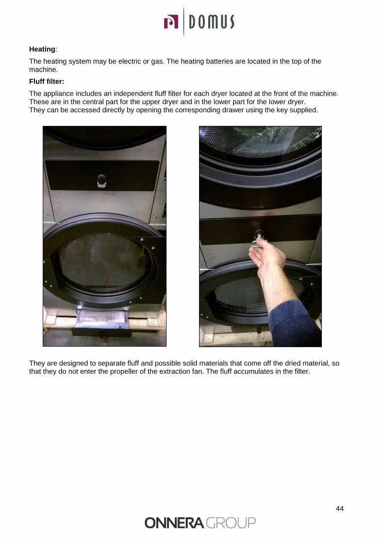
Heating:
The heating system may be electric or gas. The heating batteries are located in the top of the machine.
Fluff filter:
The appliance includes an independent fluff filter for each dryer located at the front of the machine. These are in the central part for the upper dryer and in the lower part for the lower dryer. They can be accessed directly by opening the corresponding drawer using the key supplied.
They are designed to separate fluff and possible solid materials that come off the dried material, so that they do not enter the propeller of the extraction fan. The fluff accumulates in the filter.
45
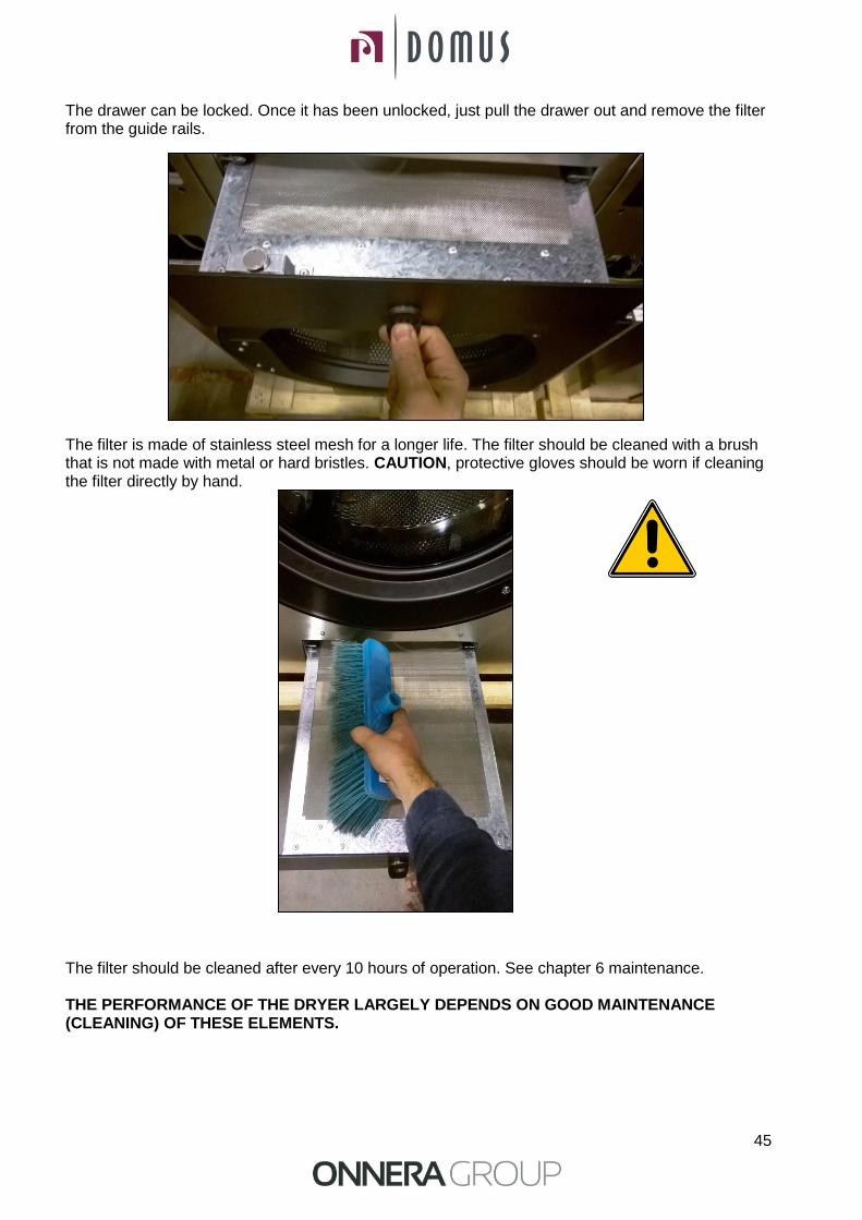
The drawer can be locked. Once it has been unlocked, just pull the drawer out and remove the filter from the guide rails.
The filter is made of stainless steel mesh for a longer life. The filter should be cleaned with a brush that is not made with metal or hard bristles. CAUTION, protective gloves should be worn if cleaning the filter directly by hand.
The filter should be cleaned after every 10 hours of operation. See chapter 6 maintenance. THE PERFORMANCE OF THE DRYER LARGELY DEPENDS ON GOOD MAINTENANCE (CLEANING) OF THESE ELEMENTS.
46
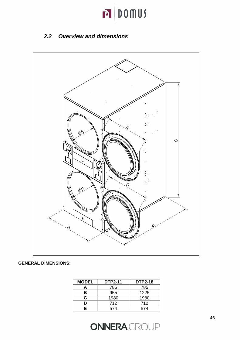
2.2 Overview and dimensions GENERAL DIMENSIONS:
MODEL DTP2-11 DTP2-18
A 785 785
B 955 1225
C 1980 1980
D 712 712
E 574 574

47
3. INSTALATION Install the machine according to current regulations
3.1 Position.
3.1.1 Transport and storage.
The machine must be transported always on its pallet and original packaging to guarantee its integrity. Transport the machine to the definitive work place.
Remove the packaging and make sure that it has not been damaged during transport. In no event install or keep the dryer outdoors.
If the machine has to be stored for a long time, cover it with its original packaging to protect it from external agents and keep it in the optimum environmental conditions. It is also recommended to disconnect it from the electricity, steam or gas supply network.
3.1.2 Location.
Install the machine in a big room to obtain efficient work conditions and to guarantee the sufficient ease of movement of the workers using the machine.
The definitive position of the machine must allow its correct use. The distances indicated on the following drawing must be observed to allow correct maintenance by authorised staff
Minimum operating space. 1.50 m at the front, and rest according to diagram.
48
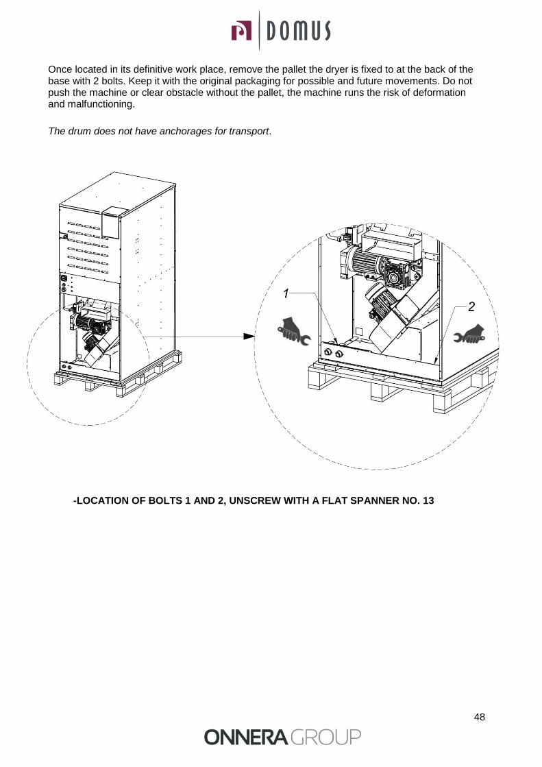
Once located in its definitive work place, remove the pallet the dryer is fixed to at the back of the base with 2 bolts. Keep it with the original packaging for possible and future movements. Do not push the machine or clear obstacle without the pallet, the machine runs the risk of deformation and malfunctioning.
The drum does not have anchorages for transport.
-LOCATION OF BOLTS 1 AND 2, UNSCREW WITH A FLAT SPANNER NO. 13
49
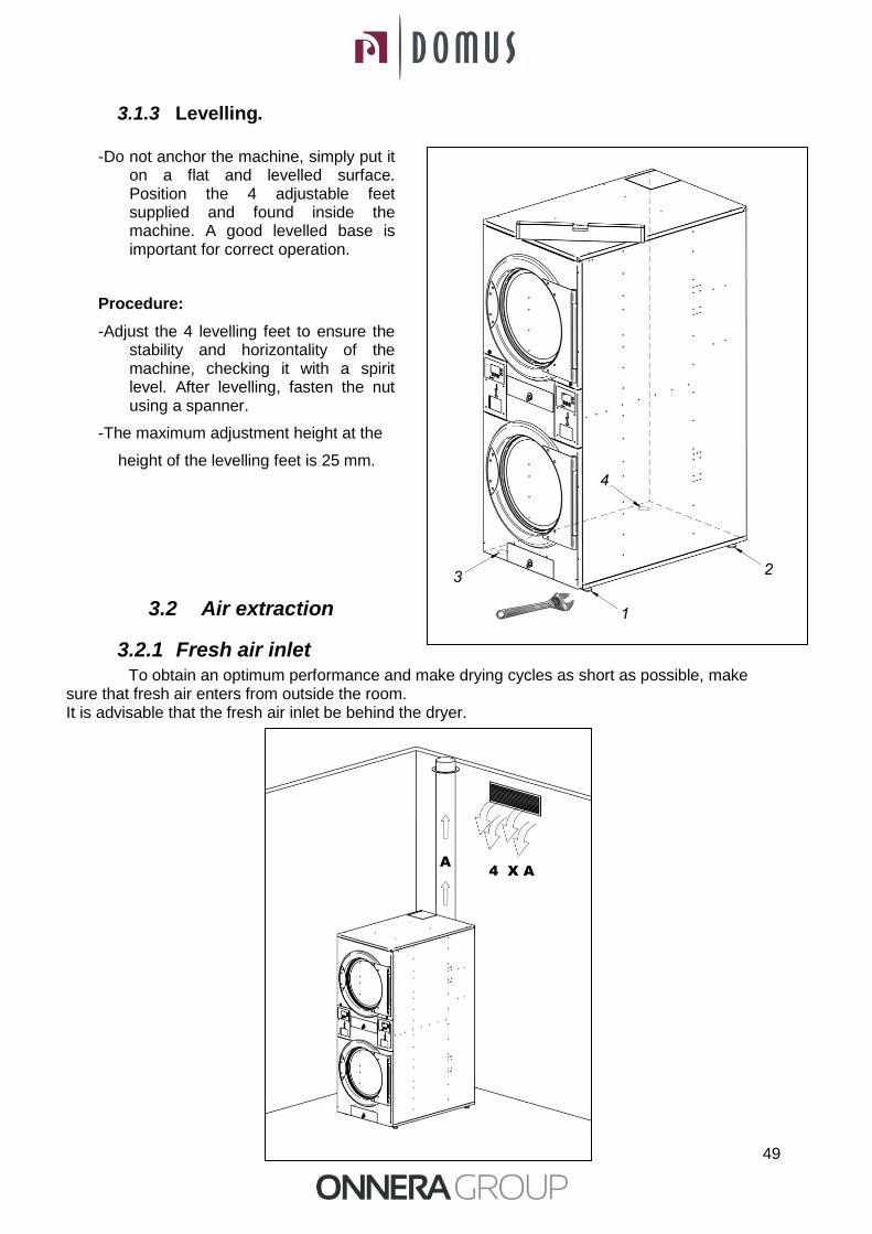
3.1.3 Levelling.
-Do not anchor the machine, simply put it
on a flat and levelled surface. Position the 4 adjustable feet supplied and found inside the machine. A good levelled base is important for correct operation.
Procedure:
-Adjust the 4 levelling feet to ensure the stability and horizontality of the machine, checking it with a spirit level. After levelling, fasten the nut using a spanner.
-The maximum adjustment height at the
height of the levelling feet is 25 mm.
3.2 Air extraction
3.2.1 Fresh air inlet To obtain an optimum performance and make drying cycles as short as possible, make
sure that fresh air enters from outside the room. It is advisable that the fresh air inlet be behind the dryer.

50
The fresh air inlet section must be at least 4 times bigger than the air outlet tube section. Note: The fresh air inlet section is equal to the section through which the air can flow without resistance due to the bars or grille installed in the inlet. Take into account that the bars or grille can often represent a big part of the inlet section.
3.2.2 Output pipe
Although the appliance has two dryers which operate independently, there is only one steam output.
The appliance has an output which may be connected directly upwards (advisable) or, if this is not possible, using a 90º L-bend to the back.
Option 90º L-bend Option directly upwards
Moist air must be channelled to the outside using the connection of a pipe with a net diameter corresponding to the outer diameter of the steam outlet tube, located on the bottom back part of the machine. The extraction air must be taken to the outside of the work place and must never be connected to other chimneys already in use that extract smoke from other fuels.
The location of these conduits must be under the limits established in environmental thermal legislation. A tube made in temperature resistant material must be used (150 ºC). Never leave the tube very near inflammable materials or materials susceptible to deformation from excessive temperatures.
The tube must be smooth inside. It is important that there are no elements in the way of the air path or that might accumulate fluff (bolts, rivets...). Systems for the periodic inspection and cleaning of the conduits must be foreseen.
The output pipe should be as short as possible. The load loss should not be more than 100 Pa (approx. 10 metres and 3 L-bends at 90º) and there should be a slope of 2% towards the outside in the horizontal sections, to prevent condensation from returning to the machine.
Note: For facilities with more linear metres of pipeline and/or more elbows consult the technical service. It may be necessary to increase the diameter of the pipeline or even install in the facility an auxiliary vacuum.
51
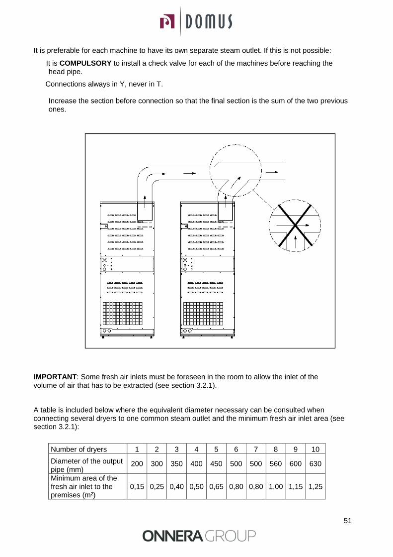
It is preferable for each machine to have its own separate steam outlet. If this is not possible:
It is COMPULSORY to install a check valve for each of the machines before reaching the head pipe.
Connections always in Y, never in T.
Increase the section before connection so that the final section is the sum of the two previous ones.
IMPORTANT: Some fresh air inlets must be foreseen in the room to allow the inlet of the
volume of air that has to be extracted (see section 3.2.1).
A table is included below where the equivalent diameter necessary can be consulted when connecting several dryers to one common steam outlet and the minimum fresh air inlet area (see section 3.2.1):
Number of dryers 1 2 3 4 5 6 7 8 9 10
Diameter of the output pipe (mm)
200 300 350 400 450 500 500 560 600 630
Minimum area of the fresh air inlet to the premises (m²)
0,15 0,25 0,40 0,50 0,65 0,80 0,80 1,00 1,15 1,25
52
3.3 Electrical connection
Although the appliance has two dryers which operate independently, there is only one electric connection.
Make sure that the characteristics of the available power supply correspond to those of your dryer, indicated on its identification plate, and that the cable section and other line accessories can supply the necessary power.
The machine leaves the factor with the complete electrical installation, and therefore you will only have to remove the cover on the back of the dryer and connect each of the terminals to the three phases L1, L2, L3 and neutral N to the terminals of the general switch.
It is COMPULSORY to insert a circuit breaker and differential switch between the wiring and the mains, and the sensitivity of the differential switch must be 300 mA. Higher sensitivity, for example 30 mA, common in domestic installations may cause operating anomalies in the machine.
Connect the three phases, neutral in the general switch and the protection cable to earth on the electrical components panel according to the following table (section in mm2).
Correct earthing is essential to guarantee the safety of users and correct operation.
ELECTRICAL CONNECTION
DTP2-11 DTP2-18
Voltage and Standard Wiring V 230I(CG,CV)-
400VIII+N+G(CE) 230I(CG,CV)-400VIII+N+G(CE)
Frequency Hz 50 / 60 (3) 50 / 60 (3)
Elé
ctri
c Cable Section 230 I + T / Fuse Nº x mm2 / A - -
Cable Section 230 III + T / Fuse Nº x mm2 / A 4 x 25 / 80 4 x 25 / 80
Cable Section 400 III + N + T / Fuse Nº x mm2 / A 5 x 10 / 40 5 x 10 / 40
Gas
Cable Section 230 I + T / Fuse Nº x mm2 / A 3 x 1,5 / 20 3 x 1,5 / 20
Cable Section 230 III + T / Fuse Nº x mm2 / A 4 x 1,5 / 20 4 x 1,5 / 20
Cable Section 400 III + N + T / Fuse Nº x mm2 / A 5 x 1,5 / 20 5 x 1,5 / 20
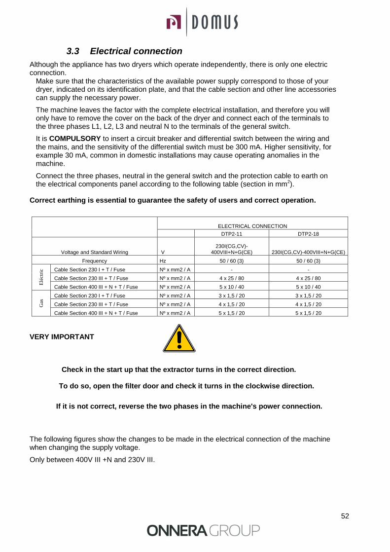
VERY IMPORTANT
Check in the start up that the extractor turns in the correct direction.
To do so, open the filter door and check it turns in the clockwise direction.
If it is not correct, reverse the two phases in the machine's power connection.
The following figures show the changes to be made in the electrical connection of the machine when changing the supply voltage.
Only between 400V III +N and 230V III.
53
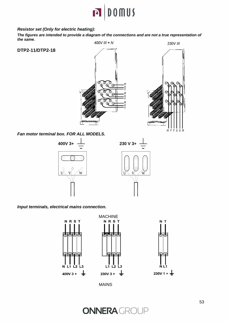
Resistor set (Only for electric heating):
The figures are intended to provide a diagram of the connections and are not a true representation of the same.
DTP2-11/DTP2-18 Fan motor terminal box. FOR ALL MODELS.
400V 3+ 230 V 3+ Input terminals, electrical mains connection.
MACHINE
MAINS
UWU V V W
54
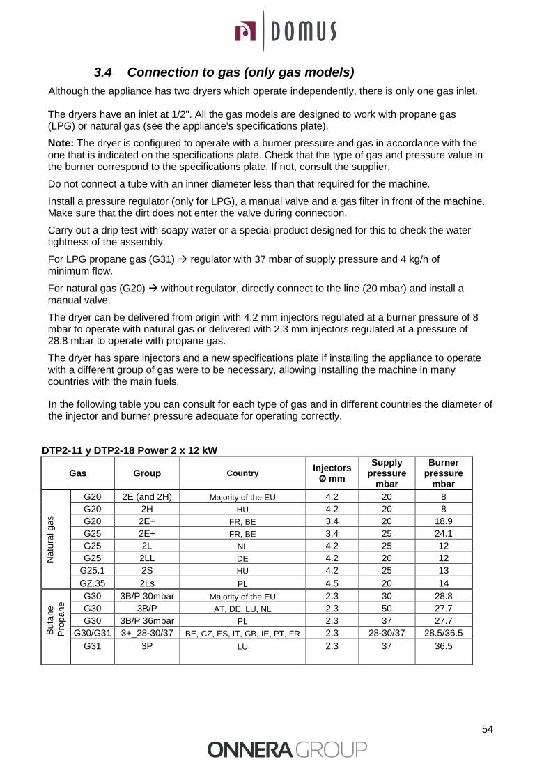
3.4 Connection to gas (only gas models)
Although the appliance has two dryers which operate independently, there is only one gas inlet. The dryers have an inlet at 1/2". All the gas models are designed to work with propane gas (LPG) or natural gas (see the appliance's specifications plate).
Note: The dryer is configured to operate with a burner pressure and gas in accordance with the one that is indicated on the specifications plate. Check that the type of gas and pressure value in the burner correspond to the specifications plate. If not, consult the supplier.
Do not connect a tube with an inner diameter less than that required for the machine.
Install a pressure regulator (only for LPG), a manual valve and a gas filter in front of the machine. Make sure that the dirt does not enter the valve during connection.
Carry out a drip test with soapy water or a special product designed for this to check the water tightness of the assembly.
For LPG propane gas (G31) regulator with 37 mbar of supply pressure and 4 kg/h of minimum flow.
For natural gas (G20) without regulator, directly connect to the line (20 mbar) and install a manual valve.
The dryer can be delivered from origin with 4.2 mm injectors regulated at a burner pressure of 8 mbar to operate with natural gas or delivered with 2.3 mm injectors regulated at a pressure of 28.8 mbar to operate with propane gas.
The dryer has spare injectors and a new specifications plate if installing the appliance to operate with a different group of gas were to be necessary, allowing installing the machine in many countries with the main fuels.
In the following table you can consult for each type of gas and in different countries the diameter of the injector and burner pressure adequate for operating correctly.
DTP2-11 y DTP2-18 Power 2 x 12 kW
Gas Group Country Injectors
Ø mm
Supply pressure
mbar
Burner pressure
mbar
Natu
ral g
as
G20 2E (and 2H) Majority of the EU 4.2 20 8
G20 2H HU 4.2 20 8
G20 2E+ FR, BE 3.4 20 18.9
G25 2E+ FR, BE 3.4 25 24.1
G25 2L NL 4.2 25 12
G25 2LL DE 4.2 20 12
G25.1 2S HU 4.2 25 13
GZ.35 2Ls PL 4.5 20 14
Buta
ne
Pro
pane G30 3B/P 30mbar Majority of the EU 2.3 30 28.8
G30 3B/P AT, DE, LU, NL 2.3 50 27.7
G30 3B/P 36mbar PL 2.3 37 27.7
G30/G31 3+_28-30/37 BE, CZ, ES, IT, GB, IE, PT, FR 2.3 28-30/37 28.5/36.5
G31 3P LU 2.3 37 36.5
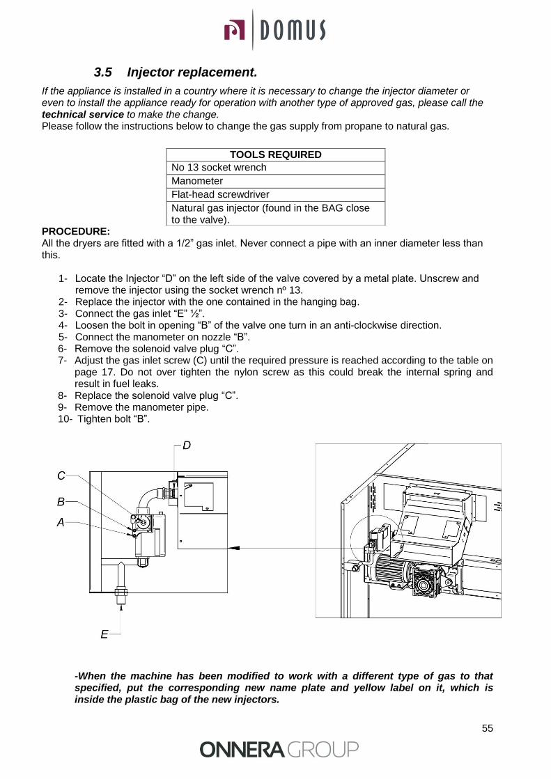
55
3.5 Injector replacement.
If the appliance is installed in a country where it is necessary to change the injector diameter or even to install the appliance ready for operation with another type of approved gas, please call the technical service to make the change. Please follow the instructions below to change the gas supply from propane to natural gas. PROCEDURE: All the dryers are fitted with a 1/2” gas inlet. Never connect a pipe with an inner diameter less than this.
1- Locate the Injector “D” on the left side of the valve covered by a metal plate. Unscrew and remove the injector using the socket wrench nº 13.
2- Replace the injector with the one contained in the hanging bag. 3- Connect the gas inlet “E” ½”. 4- Loosen the bolt in opening “B” of the valve one turn in an anti-clockwise direction. 5- Connect the manometer on nozzle “B”. 6- Remove the solenoid valve plug “C”. 7- Adjust the gas inlet screw (C) until the required pressure is reached according to the table on
page 17. Do not over tighten the nylon screw as this could break the internal spring and result in fuel leaks.
8- Replace the solenoid valve plug “C”. 9- Remove the manometer pipe. 10- Tighten bolt “B”.
-When the machine has been modified to work with a different type of gas to that specified, put the corresponding new name plate and yellow label on it, which is inside the plastic bag of the new injectors.
TOOLS REQUIRED
No 13 socket wrench
Manometer
Flat-head screwdriver
Natural gas injector (found in the BAG close to the valve).
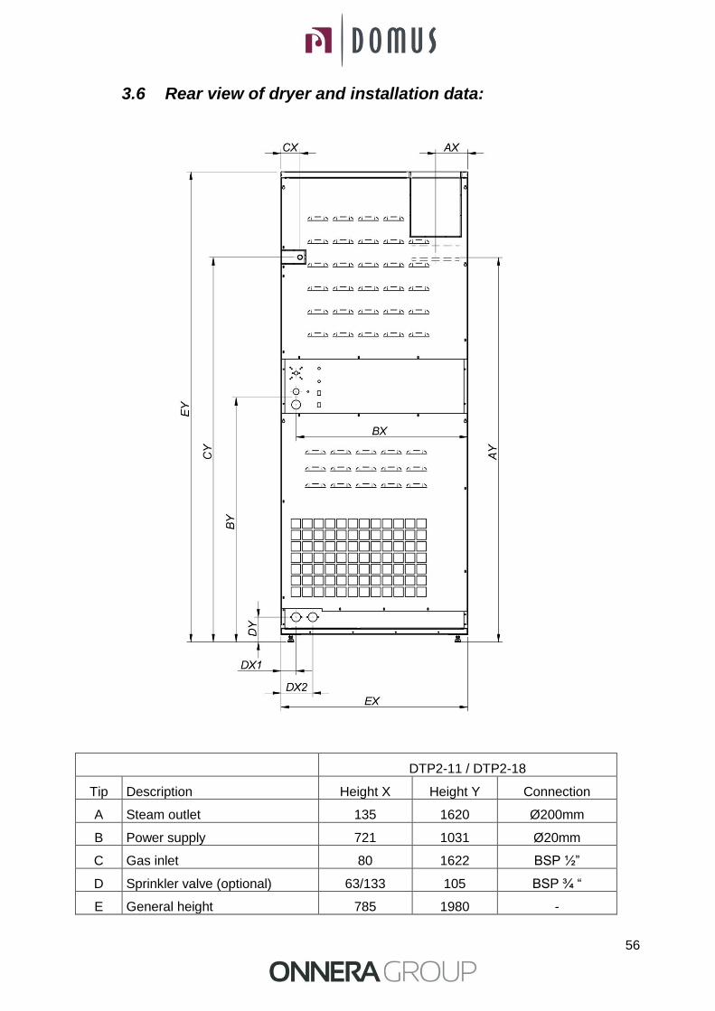
56
3.6 Rear view of dryer and installation data:
DTP2-11 / DTP2-18
Tip Description Height X Height Y Connection
A Steam outlet 135 1620 Ø200mm
B Power supply 721 1031 Ø20mm
C Gas inlet 80 1622 BSP ½”
D Sprinkler valve (optional) 63/133 105 BSP ¾ “
E General height 785 1980 -

57
4. OPERATION
4.1 Operating principle and description:
The machine dries the fibres passing hot air through the textile fibres. This air drags the humidity and sends it to the outside.
Steps for correct drying:
Choose the same type of fibre. Do not mix different types of fibres in a drying cycle.
Load the dryer.
Open the power supplies to the machine.
Select the drying programme using the microprocessor.
Push the START cycle button.
Remove the load at the end of the cycle.
WARNING. REMOVING THE LOAD WITHOUT CARRYING OUT THE COOL-DOWN (PROGRESSIVE COOLING) MAY CAUSE BURNS AND DAMAGE THE APPLIANCE.

58
4.2 Self-service versions Only three temperatures are available in self-service mode and the time is only determined by the pulses received by the microprocessor. There are no programmes. The Cool-Down period is not separated from the rest of the time and simply disconnects the heating for the last few minutes.
1. Start/Stop Button
2. Select Button: selection
3. Prog Button: Programming
4. Up/Down Buttons It has three states:
2. Waiting to receive pulses: A logo symbolising the input of coins is displayed.
INSERT COIN
2
1 4
3
4
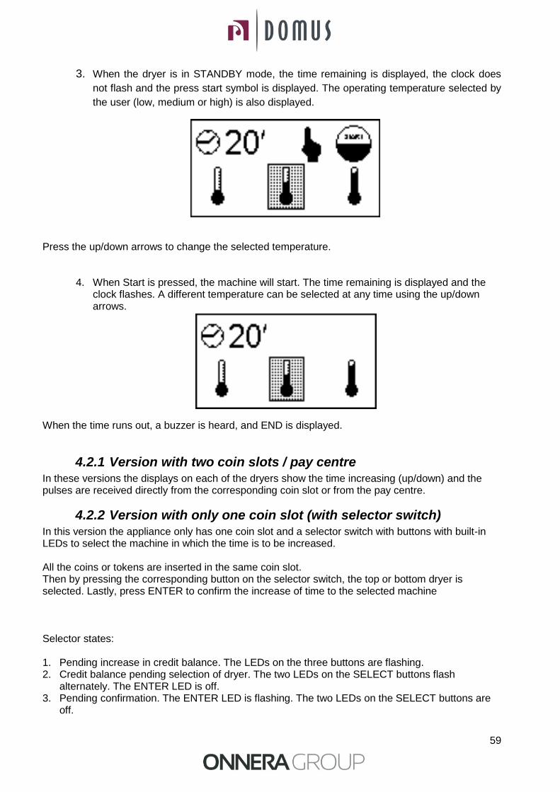
59
3. When the dryer is in STANDBY mode, the time remaining is displayed, the clock does
not flash and the press start symbol is displayed. The operating temperature selected by
the user (low, medium or high) is also displayed.
Press the up/down arrows to change the selected temperature.
4. When Start is pressed, the machine will start. The time remaining is displayed and the clock flashes. A different temperature can be selected at any time using the up/down arrows.
When the time runs out, a buzzer is heard, and END is displayed.
4.2.1 Version with two coin slots / pay centre In these versions the displays on each of the dryers show the time increasing (up/down) and the pulses are received directly from the corresponding coin slot or from the pay centre.
4.2.2 Version with only one coin slot (with selector switch) In this version the appliance only has one coin slot and a selector switch with buttons with built-in LEDs to select the machine in which the time is to be increased. All the coins or tokens are inserted in the same coin slot. Then by pressing the corresponding button on the selector switch, the top or bottom dryer is selected. Lastly, press ENTER to confirm the increase of time to the selected machine Selector states: 1. Pending increase in credit balance. The LEDs on the three buttons are flashing. 2. Credit balance pending selection of dryer. The two LEDs on the SELECT buttons flash
alternately. The ENTER LED is off. 3. Pending confirmation. The ENTER LED is flashing. The two LEDs on the SELECT buttons are
off.
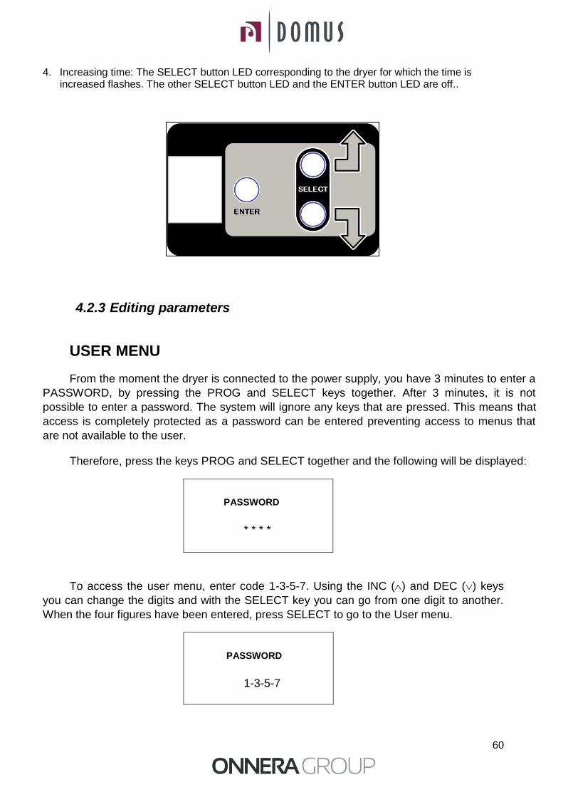
60
4. Increasing time: The SELECT button LED corresponding to the dryer for which the time is increased flashes. The other SELECT button LED and the ENTER button LED are off..
4.2.3 Editing parameters
USER MENU
From the moment the dryer is connected to the power supply, you have 3 minutes to enter a
PASSWORD, by pressing the PROG and SELECT keys together. After 3 minutes, it is not
possible to enter a password. The system will ignore any keys that are pressed. This means that
access is completely protected as a password can be entered preventing access to menus that
are not available to the user.
Therefore, press the keys PROG and SELECT together and the following will be displayed:
PASSWORD
* * * *
To access the user menu, enter code 1-3-5-7. Using the INC () and DEC () keys
you can change the digits and with the SELECT key you can go from one digit to another.
When the four figures have been entered, press SELECT to go to the User menu.
PASSWORD
1-3-5-7
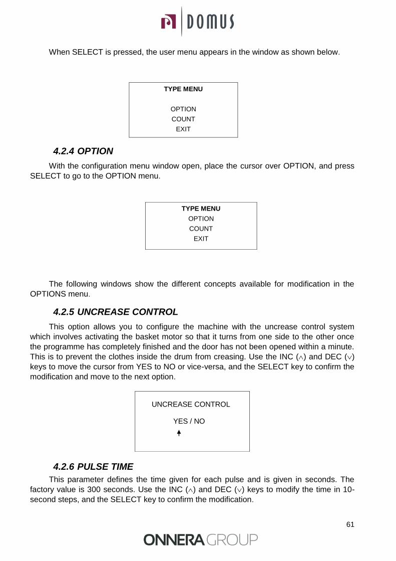
61
When SELECT is pressed, the user menu appears in the window as shown below.
TYPE MENU
OPTION
COUNT
EXIT
4.2.4 OPTION
With the configuration menu window open, place the cursor over OPTION, and press
SELECT to go to the OPTION menu.
The following windows show the different concepts available for modification in the
OPTIONS menu.
4.2.5 UNCREASE CONTROL
This option allows you to configure the machine with the uncrease control system
which involves activating the basket motor so that it turns from one side to the other once
the programme has completely finished and the door has not been opened within a minute.
This is to prevent the clothes inside the drum from creasing. Use the INC () and DEC ()
keys to move the cursor from YES to NO or vice-versa, and the SELECT key to confirm the
modification and move to the next option.
4.2.6 PULSE TIME
This parameter defines the time given for each pulse and is given in seconds. The
factory value is 300 seconds. Use the INC () and DEC () keys to modify the time in 10-
second steps, and the SELECT key to confirm the modification.
TYPE MENU
OPTION
COUNT
EXIT
UNCREASE CONTROL YES / NO
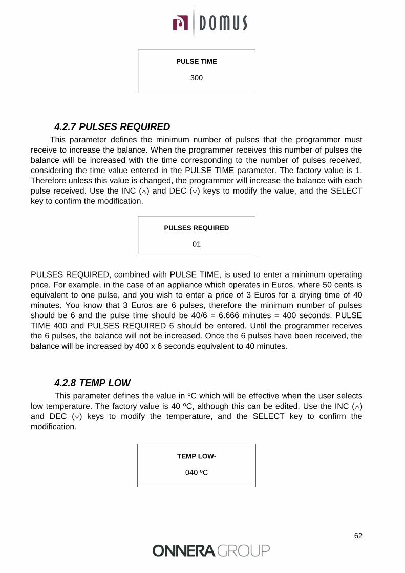
62
4.2.7 PULSES REQUIRED
This parameter defines the minimum number of pulses that the programmer must
receive to increase the balance. When the programmer receives this number of pulses the
balance will be increased with the time corresponding to the number of pulses received,
considering the time value entered in the PULSE TIME parameter. The factory value is 1.
Therefore unless this value is changed, the programmer will increase the balance with each
pulse received. Use the INC () and DEC () keys to modify the value, and the SELECT
key to confirm the modification.
PULSES REQUIRED, combined with PULSE TIME, is used to enter a minimum operating
price. For example, in the case of an appliance which operates in Euros, where 50 cents is
equivalent to one pulse, and you wish to enter a price of 3 Euros for a drying time of 40
minutes. You know that 3 Euros are 6 pulses, therefore the minimum number of pulses
should be 6 and the pulse time should be 40/6 = 6.666 minutes = 400 seconds. PULSE
TIME 400 and PULSES REQUIRED 6 should be entered. Until the programmer receives
the 6 pulses, the balance will not be increased. Once the 6 pulses have been received, the
balance will be increased by 400 x 6 seconds equivalent to 40 minutes.
4.2.8 TEMP LOW
This parameter defines the value in ºC which will be effective when the user selects
low temperature. The factory value is 40 ºC, although this can be edited. Use the INC ()
and DEC () keys to modify the temperature, and the SELECT key to confirm the
modification.
PULSE TIME
300
PULSES REQUIRED
01
TEMP LOW-
040 ºC

63
4.2.9 TEMP MID
This parameter defines the value in ºC which will be effective when the user selects
Mid temperature. The factory value is 60 ºC, although this can be edited. Use the INC ()
and DEC () keys to modify the temperature, and the SELECT key to confirm the
modification.
4.2.10 TEMP HIGH
This parameter defines the value in ºC which will be effective when the user selects
high temperature. The factory value is 80 ºC, although this can be edited. Use the INC ()
and DEC () keys to modify the temperature, and the SELECT key to confirm the
modification.
Note: This value should not be increased.
4.2.11 COOL FACTOR
After all the temperature settings have been defined, the cooling time to the end of the
cycle should be configured. The Cool Factor parameter defines the length of this cooling.
The factory setting is 0 but this can be modified. Use the INC () and DEC () keys to
modify the value, and the SELECT key to confirm the modification.
IMPORTANT! THE COOL DOWN MINUTES ARE INCLUDED IN THE SELF-
SERVICE PROGRAMME TIME
TEMP MID-
060 ºC
TEMP HIGH-
080 ºC
COOL FACTOR
001

64
4.2.12 LOST BALANCE TIME
This parameter defines the time in minutes that the dryer can remain inoperative (fan
not running) before any outstanding balance is lost. The factory value is 0, with this value
this function is deactivated, and therefore the outstanding balance is never lost. To insert a
different value, use the INC () and DEC () keys to modify the value, and the SELECT key
to confirm the modification.
4.2.13 DRUM TIME
This option allows the time in seconds that the programmer waits before changing the
direction of the drum rotation to be adjusted. The value entered remains fixed over time for
all the programmes. To modify the configuration, use the INC () and DEC () keys to
increase or decrease the time and the SELECT key to confirm the change and go to the
next option.
Note: Values below 30 seconds should not be entered.
4.2.14 MEMORY RESTORE
This option allows you to reset all the changes so that all the values of the
microprocessor are restored to the factory settings. Use the INC () and DEC () keys to
move the cursor from YES to NO or vice-versa, and the SELECT key to confirm the
modification.
LOST BAL. TIME
000
DRUM TIME 060
MEMORY RESTORE YES / NO

65
4.3 COUNT
With the technician’s menu window open, place the cursor over COUNT, and press
SELECT to go to the COUNT menu.
TYPE MENU
OPTION
COUNT
EDIT
EXIT
The count menu is shown below, the left column gives the data and the right column
gives the figures for that data.
TOTAL COUNTERS
TOTAL TIME: The total time counter gives the time during which the dryer has been switched
on. It counts in hours.
RUN TIME: The run time counter gives the time the dryer has been operating. This is not the
same as the number of hours the dryer has been switched on. It counts in minutes.
HEAT TIME: The heat time counter gives the time during which the heater has been switched
on. It counts in minutes.
T.FILTER: The T.filter counter gives the time since the filter or fluff bag was last removed for
cleaning (the counter counts the time since the filter cover was last opened). It counts in hours.
FILTER (AL-2): The Filter counter (AL-2) gives the number of times the AL-2 Alarm, filter cover
open, has been triggered.
FLAME (AL-3): The Flame counter (AL-3) gives the number of times the AL-3 Alarm, no flame,
has been triggered. This alarm is only triggered in gas-heated dryers.
A.FLOW (AL-4): The A.Flow counter (AL-4) gives the number of times the AL-4 Alarm, no air
flow in extraction, has been triggered.
TOTAL COUNTERS
TOTAL TIME 0004
RUN TIME 0023 HEAT TIME 0004
T.FILTER 0023 FILTER (AL-2) 0004 FLAME (AL-3) 0005 A.FLOW (AL-4) 0000 DRUM ALARM (AL-8) 0000 O.HEAT (AL-6) 0000
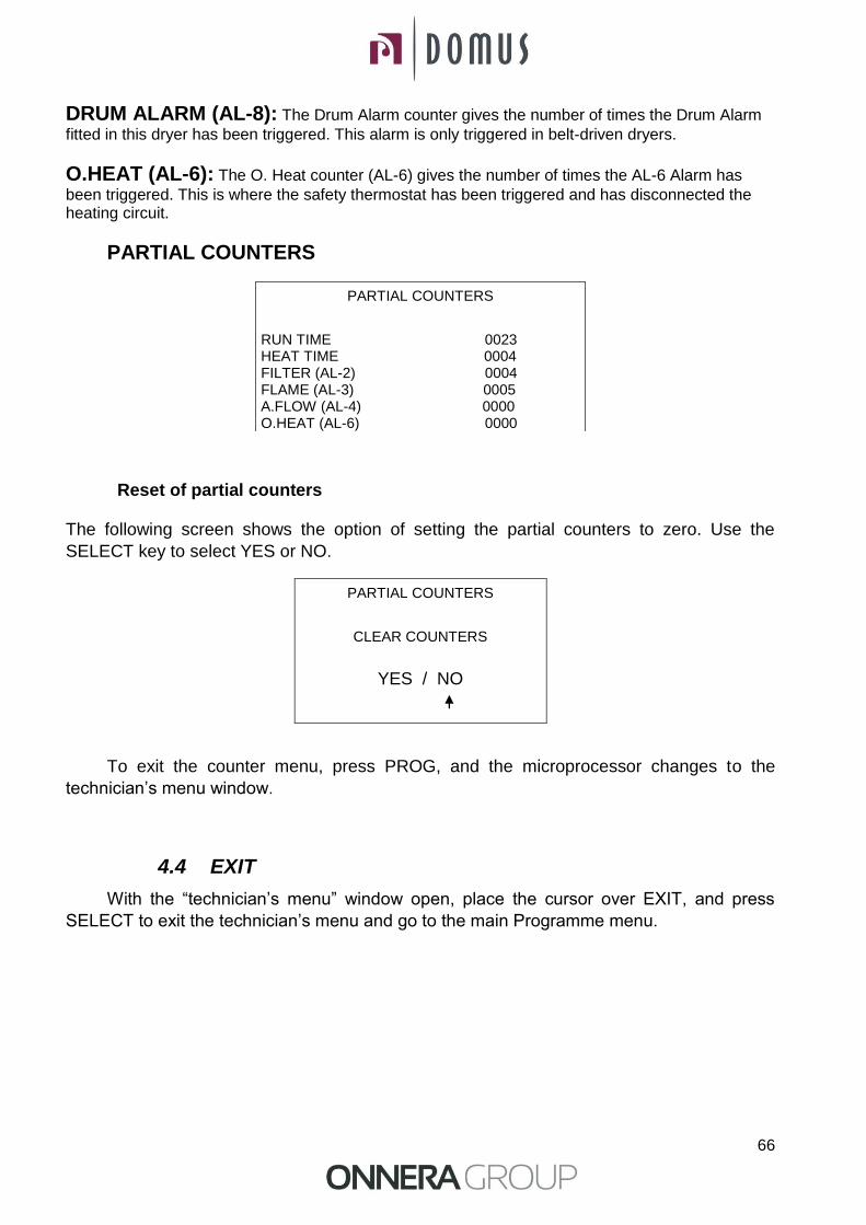
66
DRUM ALARM (AL-8): The Drum Alarm counter gives the number of times the Drum Alarm
fitted in this dryer has been triggered. This alarm is only triggered in belt-driven dryers.
O.HEAT (AL-6): The O. Heat counter (AL-6) gives the number of times the AL-6 Alarm has
been triggered. This is where the safety thermostat has been triggered and has disconnected the heating circuit.
PARTIAL COUNTERS
Reset of partial counters
The following screen shows the option of setting the partial counters to zero. Use the
SELECT key to select YES or NO.
To exit the counter menu, press PROG, and the microprocessor changes to the
technician’s menu window.
4.4 EXIT
With the “technician’s menu” window open, place the cursor over EXIT, and press
SELECT to exit the technician’s menu and go to the main Programme menu.
PARTIAL COUNTERS
RUN TIME 0023 HEAT TIME 0004 FILTER (AL-2) 0004 FLAME (AL-3) 0005 A.FLOW (AL-4) 0000 O.HEAT (AL-6) 0000
PARTIAL COUNTERS
CLEAR COUNTERS
YES / NO
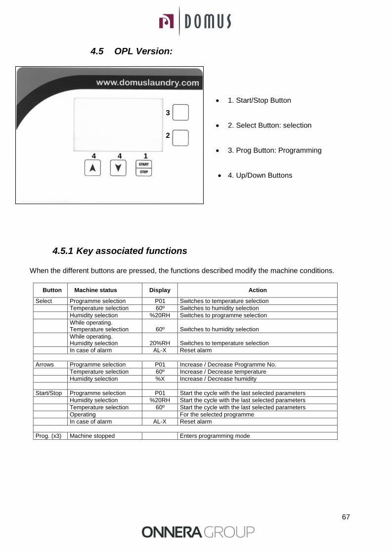
67
4.5 OPL Version:
1. Start/Stop Button
2. Select Button: selection
3. Prog Button: Programming
4. Up/Down Buttons
4.5.1 Key associated functions When the different buttons are pressed, the functions described modify the machine conditions.
Button
Machine status
Display
Action
Select Programme selection P01 Switches to temperature selection
Temperature selection 60º Switches to humidity selection
Humidity selection %20RH Switches to programme selection
While operating. Temperature selection
60º
Switches to humidity selection
While operating. Humidity selection
20%RH
Switches to temperature selection
In case of alarm AL-X Reset alarm
Arrows Programme selection P01 Increase / Decrease Programme No.
Temperature selection 60º Increase / Decrease temperature
Humidity selection %X Increase / Decrease humidity
Start/Stop Programme selection P01 Start the cycle with the last selected parameters
Humidity selection %20RH Start the cycle with the last selected parameters
Temperature selection 60º Start the cycle with the last selected parameters
Operating For the selected programme
In case of alarm AL-X Reset alarm
Prog. (x3) Machine stopped Enters programming mode
2
1 4
3
4
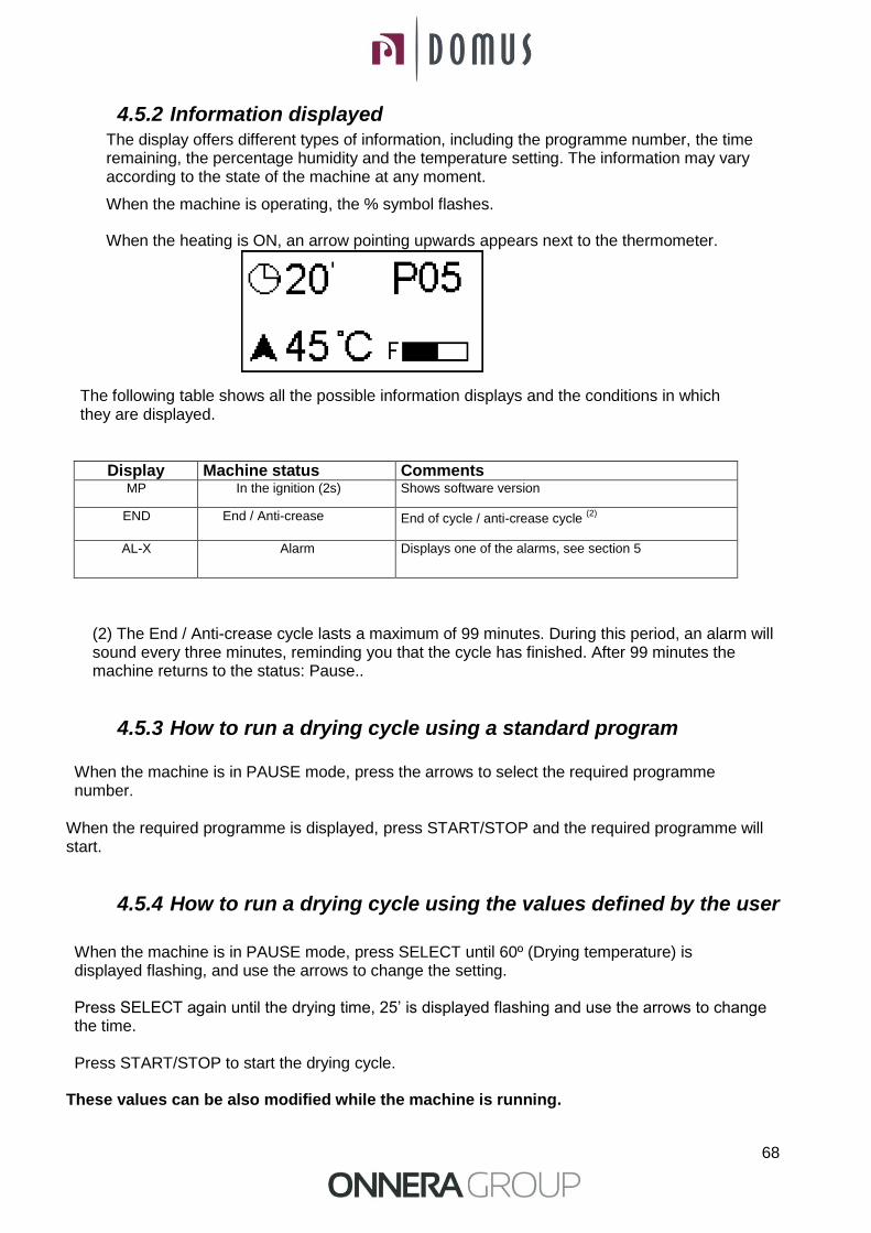
68
4.5.2 Information displayed The display offers different types of information, including the programme number, the time remaining, the percentage humidity and the temperature setting. The information may vary according to the state of the machine at any moment.
When the machine is operating, the % symbol flashes.
When the heating is ON, an arrow pointing upwards appears next to the thermometer.
The following table shows all the possible information displays and the conditions in which they are displayed.
Display Machine status Comments MP In the ignition (2s) Shows software version
END End / Anti-crease End of cycle / anti-crease cycle (2)
AL-X Alarm Displays one of the alarms, see section 5
(2) The End / Anti-crease cycle lasts a maximum of 99 minutes. During this period, an alarm will sound every three minutes, reminding you that the cycle has finished. After 99 minutes the machine returns to the status: Pause..
4.5.3 How to run a drying cycle using a standard program When the machine is in PAUSE mode, press the arrows to select the required programme number.
When the required programme is displayed, press START/STOP and the required programme will start.
4.5.4 How to run a drying cycle using the values defined by the user
When the machine is in PAUSE mode, press SELECT until 60º (Drying temperature) is displayed flashing, and use the arrows to change the setting.
Press SELECT again until the drying time, 25’ is displayed flashing and use the arrows to change the time.
Press START/STOP to start the drying cycle.
These values can be also modified while the machine is running.
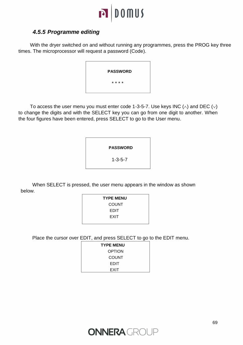
69
4.5.5 Programme editing
With the dryer switched on and without running any programmes, press the PROG key three
times. The microprocessor will request a password (Code).
To access the user menu you must enter code 1-3-5-7. Use keys INC () and DEC ()
to change the digits and with the SELECT key you can go from one digit to another. When
the four figures have been entered, press SELECT to go to the User menu.
When SELECT is pressed, the user menu appears in the window as shown
below.
TYPE MENU
COUNT
EDIT
EXIT
Place the cursor over EDIT, and press SELECT to go to the EDIT menu.
TYPE MENU
OPTION
COUNT
EDIT
EXIT
PASSWORD
* * * *
PASSWORD
1-3-5-7

70
The EDIT menu is shown below. All programmes can be edited from this menu,
allowing the user to modify all the parameters shown in the following table as required and
for each programme.
PROGRAM: With the cursor in PROGRAM, use keys INC () and DEC () to move from one programme to another (there are 9 programmes) and use SELECT key to confirm the programme to be selected and the cursor moves to TEMP.
TEMP: With the cursor on TEMP, use keys INC () and DEC () to modify the temperature of the previously selected programme. Use the SELECT key to confirm the change in the temperature and the cursor moves to the next option, TIME.
TIME: With the cursor on TIME, use keys INC () and DEC () to modify the time of the previously selected programme. Use the SELECT key to confirm the change in the time and the cursor moves to the next option, AG. TIME.
AG. TIME: With the cursor on AG TIME, use keys INC () and DEC () to modify the time the dryer takes to reverse the direction of the drum rotation. Use the SELECT key to confirm the change in the time and the cursor moves to the next option, HUMIDITY. Values below 50” should not be entered.
HUMIDITY: With the cursor on HUMIDITY, use keys INC () and DEC () to modify the relative humidity of the previously selected programme. Use the SELECT key to confirm the change in the relative humidity and the cursor moves to the next option, COOL TIME.
NOTE1: Although the humidity parameter is available, the appliance will only operate correctly when it is fitted with the humidity control option, which is never the case in standard dryers. NOTE 2: If the value entered is equal to 0, then the programme in question will operate with time so that the dryer will end the cycle at the end of the time selected in the programme and will not use the humidity sensor.
COOL TIME: With the cursor on COOL TIME, use keys INC () and DEC () to modify the cooling time required on completion of the drying cycle of the previously selected programme. Press SELECT to confirm the modification to the cooling time.
To exit the count menu, press the PROG key in the user menu, and with the cursor over EXIT, and press SELECT to exit the technician’s menu and go to the main Programme menu
PROGRAM 001 TEMPER. 060 TIME 010 AG. TIME 060 HUMIDITY 050 COOL TIME 005

71
A table is then displayed with the default parameters configured for each programme.
5. ALARMS AND WARNINGS The open door and open filter alarms lead to the pausing of the current programme. When the conditions triggering the alarm disappear, the drying cycle can be restarted as soon as the alarm is closed. The other alarms stop the programme and a warning alarm is heard. This warning is stopped by pressing SELECT or by removing the reason for the alarm.
The following table lists the alarms and their possible causes.
Alarm Meaning Possible solutions
AL-1 Door open * Close the door.
AL-2 Filter cover open * Close the filter cover.
AL-3 No flame * Check gas supply cock open. * Check that the pressure is correct. See 3.4.
AL-4 Pressure drop failure or insufficient air flow
* Check that the outlet conduit is free, check that it is not too long. * Check that the filter is fluff-free. * Check that the fan's turbine is fluff-free.
AL-5 Motor - fan overload * Check that the outlet conduit is correctly connected, and does not have a free outlet.
AL-6 Over temperature * Check that the air flow is correct. * Check gas pressure is correct. Note: the safety thermostat has to be rearmed.
AL-7 Dirty filter * Clean the filter. * Clean filter more regularly, do not reach this point. This alarm is never displayed in self-service models
AL-9 Probe Alarm * Problem with the temperature and/or humidity probes.
Contact your Technical Assistance Service.
If any of the previous alarms were to persist, consult your Technical Assistance Service. Always use the machine's serial number for your queries.
PROGRAM
RECOMMENDED USE
DRYING
ROTATION TIME
Min ºC %H.R.
1 TOWELS 30 80 25 70
2 COTTON 1 35 75 25 70
3 COTTON 2 40 65 30 70
4 SYNTHETICS 20 60 30 70
5 DELICATES 25 45 30 70
6 INTENSIVE 1 20 75 30 70
7 INTENSIVE 2 30 75 30 70
8 EXTRA 1 15 90 20 30
9 EXTRA 2 20 90 15 30
72
6. MAINTENANCE
The dryer's worst enemy is the fluff on clothes. The machine in general and its parts must not have any fluff that might hinder its operation.
The machine must be vacuumed and generally cleaned once a month.
The machine's performance is largely determined by the cleanliness of its components.
Bearing greasing is permanent for the machine's entire useful life.
6.1 Fluff filter: It is advisable once every 4 or 5 hours of operation to clean the fluff filter to obtain maximum performance in the machine.
To clean the filter, proceed as in the OPL dryers. See section 2.1 except that handles have a key lock..
6.2 Heating battery:
In the case of electrical heating, clean the accumulated fluff and dust in the battery once every two months to avoid risks.
6.3 Air extractor: Check once a month cleaning fan. Blades and blocked conduits prevent the air from circulating.
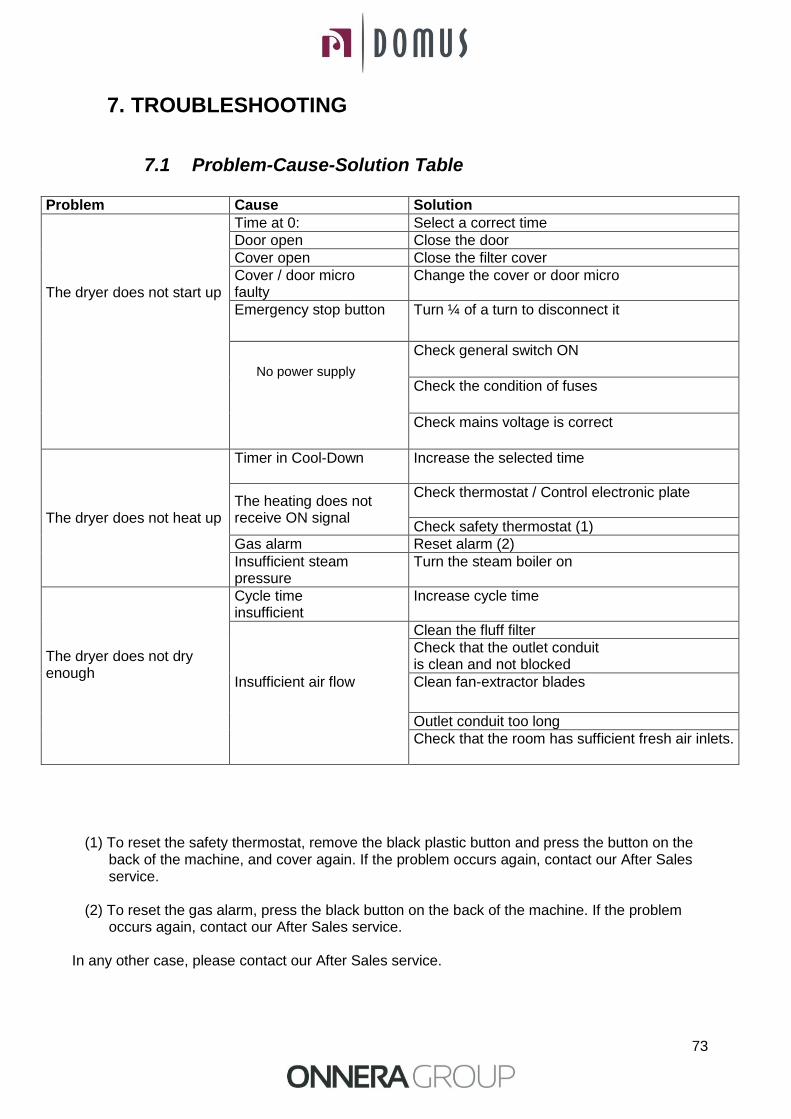
73
7. TROUBLESHOOTING
7.1 Problem-Cause-Solution Table
Problem Cause Solution
The dryer does not start up
Time at 0: Select a correct time
Door open Close the door
Cover open Close the filter cover
Cover / door micro faulty
Change the cover or door micro
Emergency stop button Turn ¼ of a turn to disconnect it
No power supply
Check general switch ON
Check the condition of fuses
Check mains voltage is correct
The dryer does not heat up
Timer in Cool-Down Increase the selected time
The heating does not receive ON signal
Check thermostat / Control electronic plate
Check safety thermostat (1)
Gas alarm Reset alarm (2)
Insufficient steam pressure
Turn the steam boiler on
The dryer does not dry enough
Cycle time insufficient
Increase cycle time
Insufficient air flow
Clean the fluff filter
Check that the outlet conduit is clean and not blocked
Clean fan-extractor blades
Outlet conduit too long
Check that the room has sufficient fresh air inlets.
(1) To reset the safety thermostat, remove the black plastic button and press the button on the back of the machine, and cover again. If the problem occurs again, contact our After Sales service.
(2) To reset the gas alarm, press the black button on the back of the machine. If the problem
occurs again, contact our After Sales service.
In any other case, please contact our After Sales service.

74
8. INDICATIONS FOR REMOVING AND DISPOSAL OF THE MACHINE.
Only European Union.
This machine is marked with the symbol that appears below.
This symbol means that in accordance with current European guidelines, the machine (or any of its parts) must be taken to a specific collection point for electrical and electronic equipment, and not to normal domestic waste containers.