MAQUETA DE TFC-PFC
64
TREBALL DE FI DE CARRERA TÍTOL DEL TFC: Femtocell Deployment; next generation in Cellular Systems TITULACIÓ: Enginyeria Tècnica de Telecomunicació, especialitat Sistemes de Telecomunicació AUTOR: Alberto Pérez Trigal DIRECTOR: Jyri Hämäläinen, Mika Husso DATA: 25 de març de 2009
Transcript of MAQUETA DE TFC-PFC

TREBALL DE FI DE CARRERA TÍTOL DEL TFC: Femtocell Deployment; next generation in Cellular Systems TITULACIÓ: Enginyeria Tècnica de Telecomunicació, especialitat Sistemes de Telecomunicació AUTOR: Alberto Pérez Trigal DIRECTOR: Jyri Hämäläinen, Mika Husso DATA: 25 de març de 2009
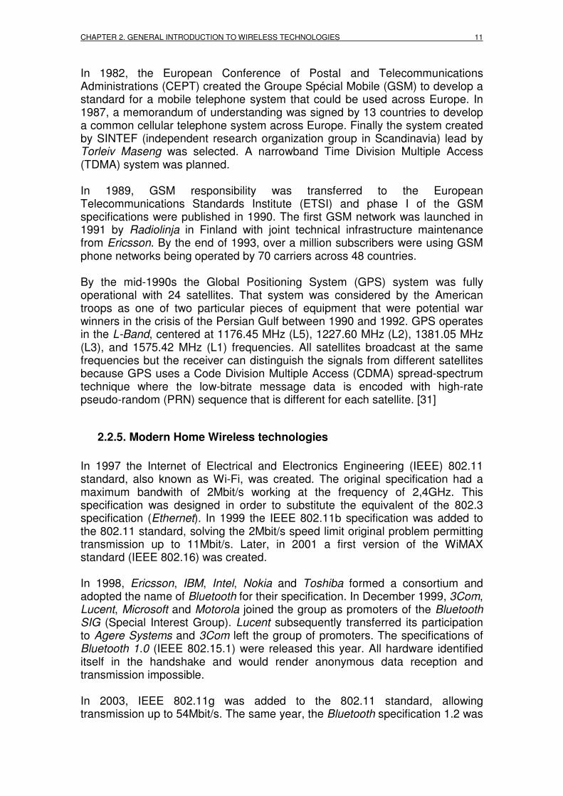
HELSINKI UNIVERSITY OF TECHNOLOGY
Faculty of Electronics, Communication and Automation
Department of Communications and Networking

Títol: Femtocell Deployment; next generation in Cellular Systems Autor: Alberto Pérez Trigal Director: Jyri Hämäläinen, Mika Husso Data: 25 de març de 2009 Resum El treball de fi de carrera que es presenta a continuació té com a objectiu donar una visió global sobre l’inclusió dels denominats Femtocells (o Home Node B) en l’àmbit dels sistemes cel·lulars actuals. El propòsit fonamental és donar una idea clara i simple sobre el concepte dels Femtocells, així com explicar els beneficis i prejudicis o inconvenients de la utilització en massa d’aquests serveis tant per als consumidors com per les empreses associades a aquest fenomen. En aquest text també es pot trobar un repàs no molt extens sobre les tecnologies sense fils al llarg de la història de les telecomunicacions, així com una introducció a les diferents tecnologies sense fils més esteses en l’actualitat, amb un especial interès en el concepte dels sistemes cel·lulars. En l’últim capítol també es pot trobar una explicació matemàtica simple sobre el concepte de la interferència dels Femtocells en un sistema macrocelular, i un raonament sobre les seves possibles solucions.

Title: Femtocell Deployment; next generation in Cellular Systems
Author: Alberto Pérez Trigal
Director: Jyri Hämäläinen, Mika Husso
Date: March, 25th 2009 Overview The final Bachelor’s Thesis that is shown below has such a final purpose of giving an overview of the inclusion of the so-called Femtocells (or Home Node B) in the current cellular systems. The main objective is to give a clear but simple idea about the concepts of Femtocells, as well as to explain the benefits and disadvantages of the mass uses of these services both for consumers and associated companies with this phenomenon. In this text it is also possible to find a brief review of wireless technologies throughout the history of telecommunications, as well as an introduction to the more current wireless technologies, with a special interest in the concept of cellular systems. In the last chapter a simple mathematical explanation of the key issue of interference between Femtocells and macrocellular networks is presented, with a brief argument about possible solutions.

TABLE OF CONTENTS
CHAPTER 1. INTRODUCTION.......................................................................... 7
1.1. The scope of 3G: Home Invasion..................................................................................... 7
CHAPTER 2. GENERAL INTRODUCTION TO WIRELESS TECHNOLOGIES 8
2.1. Overview................................................................................................................................ 8
2.2. History of Wireless Technology ......................................................................................... 8 2.2.1. First steps in telecommunications ............................................................................. 8 2.2.2. Key issue: Radio invention ........................................................................................ 9 2.2.3. Radio become useful............................................................................................... 10 2.2.4. Cellular Systems were born..................................................................................... 10 2.2.5. Modern Home Wireless technologies...................................................................... 11
2.3. Wireless Technologies – Cellular Systems ..................................................................... 12 2.3.1 Overview................................................................................................................... 12 2.3.2. Digital/Analog Broadcast System ............................................................................ 12 2.3.3. Amateur Radio......................................................................................................... 13 2.3.4. Satellite Mobile System ........................................................................................... 14 2.3.5. Professional Mobile Radio....................................................................................... 15 2.3.6. Cordless Technology............................................................................................... 16 2.3.7. Cellular Systems...................................................................................................... 17
2.3.7.1. GSM ............................................................................................................... 18 2.3.7.1.1. Base Station Subsystem (BSS)............................................................... 19 2.3.7.1.2. Network and Switching Subsystem (NSS) .............................................. 19 2.3.7.1.3. GSM Internet access ............................................................................... 22
2.3.7.2. GPRS ............................................................................................................. 23 2.3.7.3. EDGE ............................................................................................................. 24 2.3.7.4. UMTS ............................................................................................................. 25
2.3.8. Wireless sensor networks (WPAN) ......................................................................... 27 2.3.8.1. Bluetooth ........................................................................................................ 27 2.3.8.2. ZigBee............................................................................................................ 28 2.3.8.3. UWB............................................................................................................... 29
2.3.9. Wireless computer networks (WLAN) ..................................................................... 29
CHAPTER 3. FEMTOCELL TECHNOLOGY FRAMEWORK.......................... 31
3.1. Femtocell Supporters (Industry Partnership).................................................................. 31 3.1.1. Femto Forum ........................................................................................................... 31 3.1.2. 3GPP ....................................................................................................................... 32 3.1.3. 3GPP2 ..................................................................................................................... 32 3.1.4. The Broadband Forum ............................................................................................ 33 3.1.5. Next Generation Mobile Network ............................................................................ 34 3.1.6. GSM Association ..................................................................................................... 35
CHAPTER 4. FEMTOCELLS/HOME BASE STATIONS ................................. 36
4.1. Femtocell Technology ....................................................................................................... 36
4.2. Femtocell Benefits ............................................................................................................. 38 4.2.1. Consumer Benefits .................................................................................................. 39 4.2.2. Commercial Point of View ....................................................................................... 40
4.2.2.1. Operators stumbling blocks ........................................................................... 40

4.2.2.2. Operators Benefits ......................................................................................... 41 4.2.2.3. Service and Marketing Issues........................................................................ 41
4.2.3. Femtozone Services................................................................................................ 42
4.3. Convergence of Femtocell and Wi-Fi ............................................................................... 43
4.4. Femtocells and Health ....................................................................................................... 45
4.5. Overview of the technical implementation of HNB......................................................... 46 4.5.1. Network implementations ........................................................................................ 47
4.6. Interference in Femtocell deployment ............................................................................. 51 4.6.1. Interference case 1: User in room 6 connected to HNB in room 5.......................... 54 4.6.2. Interference case 2: User in room 5 connected to MNB ......................................... 56 4.6.3. Adaptive antennas and dynamic spectrum management ....................................... 57
CHAPTER 5. CONCLUSIONS......................................................................... 59
GLOSSARY ..................................................................................................... 60
BIBLIOGRAPHY.............................................................................................. 62

CHAPTER 1. INTRODUCTION 7
CHAPTER 1. INTRODUCTION
1.1. The scope of 3G: Home Invasion The deployment of third-generation (3G) cellular networks has been one of the dominant themes in wireless over the past several years. Now 3G, combined with the rapid uptake to residential broadband services, could launch a new phase in mobile networking and service provisioning. The idea is to take the capability of low-cost IP access and combine it with the robustness and usability of carrier-grade telephony services by deploying ultra-low-cost, low-power, cellular base station in subscribers’ homes. Also known as femtocells, home base stations or 3G access points, theses devices typically support around four to six simultaneous users and look similar to a residential Wireless Local-Area Network (WLAN) access point. The major difference between femtocells and dual-mode Fixed-Mobile Convergence (FMC) is that this technology works with millions of mobile handsets already in use. In fact, there is a disjunctive between charging cost and complexity into end-users with handsets that support Wi-Fi technology and adding devices to a subscriber's home network. There are multiple business drivers for the femtocell concept. Most obviously, by deploying capacity indoors, where it is most needed, cellular operators gain greater flexibility to introduce disruptive pricing strategies, allowing them to accelerate the capture of wireline voice minutes and grow revenues. Over the long term, there is also an opportunity to develop services that take advantage of low-cost, high-speed internet access to mobile devices, which could include free video calling or mobile TV from home. Service innovation could potentially also extend to applications that use handsets to access and control multimedia home networks. Other benefits of home base station technology over traditional cellular network technology include the ability to provide capacity that scales in line with subscriber demand, a reduced requirement to deploy additional macro carriers to support indoor users, and an operating expenses (opex) requirement that is kept in check by IP backhaul paid for by the costumer. [3]

CHAPTER 2. GENERAL INTRODUCTION TO WIRELESS TECHNOLOGIES
2.1. Overview Wireless is a very generic term that refers to numerous forms of transmission that do not use metal wires or optical fibers. In Wireless the communication is possible using electromagnetic waves, facilitating services such as long range communications impossible or impractical to implement with the use of wires. Wireless communications is generally considered to be a branch of telecommunications where the systems use some form of energy to transfer information without the use of wires, transferring in this manner over both short and long distance.
2.2. History of Wireless Technology
2.2.1. First steps in telecommunications The first wireless networks were developed in the pre-industrial age. These systems transmitted information over long distances using smoke signals, torch signalling, flashing mirrors, signal flares or semaphore flags. Some rules were created in order to convert these rudimentary signals in complete messages. Observation stations were built on hilltops and along roads to relay these messages over larger distances. After the invention, first of the telegraph in 1838 by Samuel Morse, and then the telephone, patented by Alexander Graham Bell in 1876, these archaic communication systems were obsolete. At the same time during the XIX century Hans Christian Oersted and Michael Faraday were working on what is considered the beginning of electromagnetism. Oersted noted in 1819 that a compass needle would move in the presence of an electric field, thus establishing the fundamental relationship between electricity and magnetism. In 1831, Faraday demonstrated electromagnetic induction and built the first direct-current generator. While this was not useful for wireless communications, it did provide a way to generate electricity. But the history should wait until James Clerk Maxwell who described the theoretical bases of the electromagnetic waves in a document sent to the Royal Society titled "On a Dynamical Theory of the Electromagnetic Field", which was the brief of his work between 1861 and 1885, and where the famous Maxwell Equations were included. Building on Maxwell's work, Heinrich Hertz, between 1886 and 1888, was the first to experimentally validate the theory of Maxwell, demonstrating that the radio emission had all the properties of waves and discovering that the electromagnetic equations could be reformulated into a

CHAPTER 2. GENERAL INTRODUCTION TO WIRELESS TECHNOLOGIES 9
partial differential equation called “The Wave Equation”. Hertz took a giant step affirming that the waves propagated at electromagnetic speed similar to the speed of light. These scientists had the technical basis for the radio to come out ahead, since the propagation of electromagnetic waves was essential to develop what later became one of the great mass media. [18], [19]
2.2.2. Key issue: Radio invention It is difficult to attribute the invention of the first wireless technology, the radio, to a single person. In the 1890’s three scientists around the world were working in radio development; Aleksandr Stepanovich Popov made his first demonstration in St. Petersburg, Russia; Nikola Tesla in St. Louis, Missouri, United States; and Guglielmo Marconi was the first to implement and market the invention in United Kingdom. On May 7, 1895 Popov had submitted a receiver able to detect electromagnetic waves. Ten months later, on March 24, 1896, with a complete radiation-receipt telegraph system, he transmitted the first telegraph message between two buildings within a distance of 250m at the University of St. Petersburg. In 1896, Marconi received the world's first patent on radio, but countries like France or Russia rejected to recognize this patent, referring to the publications of Popov, prior in time. In 1897, Marconi set up the first radio station in the world on the Isle of Wight, southern England and in 1898 opened the first factory of wireless transmission equipment in Hall Street (Chelmsford, UK). In 1899 Marconi succeeded in establishing telegraphic communication between Britain and France. Nothing compared with the feat two years later, in 1901, when he made possible to transmit signals across the Atlantic Ocean. Nikola Tesla, in San Luis (Missouri, United States) made his first public demonstration of radio in 1893. Addressing the Franklin Institute in Philadelphia and the National Electric Light Association described and demonstrated in detail the principles of the radio. Their equipment already contained all the elements that were used in radio systems to the development of vacuum tubes. In the United States, some key developments in the early history of radio were developed and patented in 1897 by Tesla. However, the Patent Office of the United States reversed their decision in 1904 and awarded Marconi a patent for the invention of radio, possibly influenced by the financial sponsors of Marconi in the United States, among them Thomas Alva Edison and Andrew Carnegie. Years later, in the sixties, the Supreme Court of the United States determined that the patent on the radio was legitimately owned by Tesla, recognizing him as the legal inventor of it, although this did not transpired to the public that still regarded Marconi as its inventor. On December 12, 1901, Marconi transmitted, for the first time, Morse signals by electromagnetic waves. The invention of Amplitude-Modulated (AM) radio, so that more than one station can send signals (as opposed to spark-gap radio, where one transmitter covers the entire bandwidth of the spectrum) is attributed to Reginald Fassenden and

Alexander Lee de Forest. On Christmas Eve 1906, Reginald Fassenden using the heterodyne principle made the first radio audio broadcast, from Brant Rock, Massachussetts. Ships at sea heard a broadcast that included Fessenden playing “O Holy Night” on the violin and reading a passage from the Bible. On 1918, Edwin Armstrong invented the superheterodyne receiver, enabling better quality in the transmissions. [17], [19]
2.2.3. Radio become useful In 1921, the Detroit (Michigan, United States) police department installed the first land mobile radio telephone system for police car dispatch. It was one-way transmission only and the patrolmen had to stop at a wire-line telephone station to call back in. On April, 1928, the first voice based radio mobile system became operational. In 1933, Armstrong again described a high quality radio system, less sensitive to radioelectric interference than AM, using Frequency Modulation (FM). On 1948, perhaps the biggest event in communications happened when Claude Shannon developed his “A mathematical theory of communication “ where he demonstrated that all kind of sources of information (electric telegraph, telephone, radio, people speaking, television cameras, etc.) are measurable and the communication channels have a similar unit of measure. He also showed that the information can be transmitted over a channel only if the magnitude of the source does not exceed the transmission capacity of the channel, and laid the foundations for error correction, noise suppression and redundancy. On 7 October, 1957, “Sputnik 1”, the first satellite of the Sputnik program was launched to the space as the first human-made object to orbit the Earth. The “Sputnik 1” incorporated two radio transmitters at the frequency of 20,007 and 40,002 MHz. [18]
2.2.4. Cellular Systems were born In the late 1970s AT&T Bell Laboratories began working with several leading United States and Japanese companies to create a cellular telephone system based on dividing coverage areas into small cells and reusing frequencies. Previous mobile telephone technologies operated on limited numbers of channels, thus limiting the number of users in any given coverage area to a very small number. The result was low usage and costly service and equipment. The first commercial launch of cellular telecommunications was released by NET in Tokyo, Japan, in 1979. In 1981 the Nordic Mobile Telephone (NMT) system was launched in Denmark, Finland, Norway and Sweden (Scandinavian area) and finally, a core group was created to develop a standard called the Advanced Mobile Phone Service (AMPS), launched in 1983 in Chicago, Illinois, United States.
CHAPTER 2. GENERAL INTRODUCTION TO WIRELESS TECHNOLOGIES 11
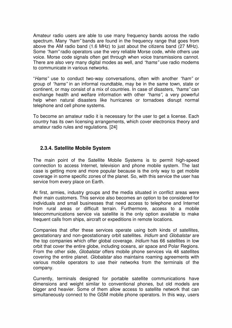
In 1982, the European Conference of Postal and Telecommunications Administrations (CEPT) created the Groupe Spécial Mobile (GSM) to develop a standard for a mobile telephone system that could be used across Europe. In 1987, a memorandum of understanding was signed by 13 countries to develop a common cellular telephone system across Europe. Finally the system created by SINTEF (independent research organization group in Scandinavia) lead by Torleiv Maseng was selected. A narrowband Time Division Multiple Access (TDMA) system was planned. In 1989, GSM responsibility was transferred to the European Telecommunications Standards Institute (ETSI) and phase I of the GSM specifications were published in 1990. The first GSM network was launched in 1991 by Radiolinja in Finland with joint technical infrastructure maintenance from Ericsson. By the end of 1993, over a million subscribers were using GSM phone networks being operated by 70 carriers across 48 countries. By the mid-1990s the Global Positioning System (GPS) system was fully operational with 24 satellites. That system was considered by the American troops as one of two particular pieces of equipment that were potential war winners in the crisis of the Persian Gulf between 1990 and 1992. GPS operates in the L-Band, centered at 1176.45 MHz (L5), 1227.60 MHz (L2), 1381.05 MHz (L3), and 1575.42 MHz (L1) frequencies. All satellites broadcast at the same frequencies but the receiver can distinguish the signals from different satellites because GPS uses a Code Division Multiple Access (CDMA) spread-spectrum technique where the low-bitrate message data is encoded with high-rate pseudo-random (PRN) sequence that is different for each satellite. [31]
2.2.5. Modern Home Wireless technologies In 1997 the Internet of Electrical and Electronics Engineering (IEEE) 802.11 standard, also known as Wi-Fi, was created. The original specification had a maximum bandwith of 2Mbit/s working at the frequency of 2,4GHz. This specification was designed in order to substitute the equivalent of the 802.3 specification (Ethernet). In 1999 the IEEE 802.11b specification was added to the 802.11 standard, solving the 2Mbit/s speed limit original problem permitting transmission up to 11Mbit/s. Later, in 2001 a first version of the WiMAX standard (IEEE 802.16) was created. In 1998, Ericsson, IBM, Intel, Nokia and Toshiba formed a consortium and adopted the name of Bluetooth for their specification. In December 1999, 3Com, Lucent, Microsoft and Motorola joined the group as promoters of the Bluetooth SIG (Special Interest Group). Lucent subsequently transferred its participation to Agere Systems and 3Com left the group of promoters. The specifications of Bluetooth 1.0 (IEEE 802.15.1) were released this year. All hardware identified itself in the handshake and would render anonymous data reception and transmission impossible. In 2003, IEEE 802.11g was added to the 802.11 standard, allowing transmission up to 54Mbit/s. The same year, the Bluetooth specification 1.2 was

released, including Adaptative Frequency-Hoping (AFH) while reducing Radio-Frequency (RF) interference. One year later, in 2004, a newest version of IEEE 802.16 was added that completely changes the WiMAX standard. A new scheduling algorithm made WiMAX much more scalable than Wi-Fi. In this new scheduling algorithm subscribers compete once for a time to talk when they connect to the network, instead of competing randomly as Wi-Fi requires. Transmission then occurs at the time specified reducing collisions. WiMAX hardware also has a theoretical 15 miles radius for a non-line of sight topology. Also Bluetooth specification 2.0 was released. The new specification is backwards compatible with the old specifications; also it introduced Enhanced Data Rate (EDR) allowing transmission of data up to 3MBit/s. [21], [38], [39]
2.3. Wireless Technologies – Cellular Systems
2.3.1 Overview Wireless applications are used in a lot of fields of the current life. A first classification of the wireless technologies could be done thinking of implementations, devices and standard. In this way, wireless technologies can be divided into:
- Digital/Analog Broadcast System - Amateur Radio - Satellite mobile system - Professional Mobile Radio - Cordless Technology - Cellular Systems - Wireless sensor networks - Wireless computer networks
2.3.2. Digital/Analog Broadcast System It refers to all of those services that transmit audio and/or video signals to all the receptors in a region, such the radio or television services. Traditionally radio programmes were broadcast on different frequencies via FM and AM, and the radio had to be tuned into each frequency. These systems used large amount of spectrum for a relatively small number of stations, limiting listening choice. Since 2006, a lot of countries, especially in Europe are using Digital Audio Broadcasting (DAB) standard to broadcast radio. DAB is a system that through the application of multiplexing and compression combines multiple audio streams onto a single broadcast frequency called DAB ensemble. DAB gives substantially higher spectral efficiency, measured in programmes per MHz

CHAPTER 2. GENERAL INTRODUCTION TO WIRELESS TECHNOLOGIES 13
and per transmitter site, than analogue communication. This has led to a vast increase in the number of stations available to listeners, especially outside of the major urban conurbations. DAB uses a wide-bandwidth broadcast technology and typically spectrum have been allocated for it in Band III (174–240 MHz) and L band (1452–1492 MHz), although the scheme allows for operation almost anywhere above 30 MHz. DAB has a number of country specific transmission modes (I, II, III and IV). For worldwide operation a receiver must support all 4 modes:
- Mode I for Band III, Earth - Mode II for L-Band, Earth and satellite - Mode III for frequencies below 3 GHz, Earth and satellite - Mode IV for L-Band, Earth and satellite
Immunity to fading and inter-symbol interference (caused by multipath propagation) is achieved without equalization by means of the Orthogonal Frequency Division Multiplexing (OFDM) and Differential Quadrature Phase Shift Keying (DQPSK) modulation techniques. Regarding television, until 2003, the most commonly used frequency bands were Ultra High Frequency (UHF, a range of electromagnetic waves with frequencies between 300 MHz and 3 GHz) and Very High Frequency (VHF, the radio frequency range from 30 MHz to 300 MHz). But nowadays, most of the countries following the “Analogue switch-off” program, are changing their broadcasting mode to the Digital Video Broadcasting – Terrestrial (DVB-T) standard. DVB-T uses Coded Orthogonal Frequency Division Multiplexing (COFDM), which uses as many as 8000 independent carriers, each transmitting data at a comparatively low rate. This system was designed to provide superior immunity from multipath interference, and has a choice of system variants which allow data rates from 4MBit/s up to 24MBit/s. Hence, in United States and Canada they use another system called Advanced Television System Committee (ATSC). This system uses a proprietary Zenith-developed modulation called 8-VSB (Vestigial Side-Band) technique. Essentially, analogue VSB is to regular amplitude modulation as 8-VSB is to eight-way quadrature amplitude modulation. [27]
2.3.3. Amateur Radio Amateur radio is a worldwide group of people who communicate with each other over a wide frequency spectrum using many different types of wireless transmitting modes. Often called “ham” radio, amateur radio is both a hobby and a service in which participants try to communicate with other radio amateur for public service, recreation and self-training. The term amateur is not reflection on the skills of the participants, which are often quite advanced. Rather, amateur indicates that the services are not allowed to be made for commercial or money-making purposes.
Amateur radio users are able to use many frequency bands across the radio spectrum. Many “ham” bands are found in the frequency range that goes from above the AM radio band (1.6 MHz) to just about the citizens band (27 MHz). Some “ham” radio operators use the very reliable Morse code, while others use voice. Morse code signals often get through when voice transmissions cannot. There are also very many digital modes as well, and “hams” use radio modems to communicate in various networks. “Hams” use to conduct two-way conversations, often with another “ham” or group of “hams” in an informal roundtable, may be in the same town, state or continent, or may consist of a mix of countries. In case of disasters, “hams” can exchange health and welfare information with other “hams”, a very powerful help when natural disasters like hurricanes or tornadoes disrupt normal telephone and cell phone systems. To become an amateur radio it is necessary for the user to get a license. Each country has its own licensing arrangements, which cover electronics theory and amateur radio rules and regulations. [24]
2.3.4. Satellite Mobile System The main point of the Satellite Mobile Systems is to permit high-speed connection to access Internet, television and phone mobile system. The last case is getting more and more popular because is the only way to get mobile coverage in some specific zones of the planet. So, with this service the user has service from every place on Earth. At first, armies, industry groups and the media situated in conflict areas were their main customers. This service also becomes an option to be considered for individuals and small businesses that need access to telephone and Internet from rural areas or difficult terrain. Furthermore, access to a mobile telecommunications service via satellite is the only option available to make frequent calls from ships, aircraft or expeditions in remote locations. Companies that offer these services operate using both kinds of satellites, geostationary and non-geostationary orbit satellites. Iridium and Globalstar are the top companies which offer global coverage. Iridium has 66 satellites in low orbit that cover the entire globe, including oceans, air space and Polar Regions. From the other side, Globalstar offers mobile phone services via 48 satellites covering the entire planet. Globalstar also maintains roaming agreements with various mobile operators to use their networks from the terminals of the company. Currently, terminals designed for portable satellite communications have dimensions and weight similar to conventional phones, but old models are bigger and heavier. Some of them allow access to satellite network that can simultaneously connect to the GSM mobile phone operators. In this way, users

CHAPTER 2. GENERAL INTRODUCTION TO WIRELESS TECHNOLOGIES 15
can make calls using a mobile phone operator when they have GSM coverage (cheaper calls) and use satellite system calls when cannot find any available wireless connection. The cost of these terminals are high, between 400 and 2000€, adding the cost of additional accessories such as batteries, solar charger or external antennas for greater capacity if is needed to use in remote locations. For mobile satellite communications, companies can use the radio band between 1980 and 2100 MHz for communications from Earth to space, and between 2170 and 2200 MHz for the downlink.
2.3.5. Professional Mobile Radio Professional Mobile Radio (also known as Private Mobile Radio (PMR) in the UK and Land Mobile Radio (LMR) in North America) are all of those systems designed for dedicated use by specific organizations such emergency first responder organizations, public works organizations, or companies with large vehicle fleets or numerous field staff. This system was developed for business users who need to keep in contact over relatively short distances with a central base station, for instance, a taxi company. From their early designs, PMR systems have developed into “trunked” systems, the most notable of which is Terrestrial “Trunked” Radio (TETRA). Trunking is a technique where the resources of the communications networks are shared, thus providing both flexibility and economy in the allocation of network resources. “Trunked” systems use a few channels and can have virtually unlimited talkgroups. The control channel computer sends packets of data to enable one talkgroup to talk each other, independently of frequency. “Trunked” radio takes advantage of the probability that in any given number of user units, not everyone will need channel access at the same time. Therefore with a given number of users, fewer discrete radio channels are required. From another perspective, with a given number of radio channels, a much greater number of user groups can be accommodated. In the example of the police department, this additional capacity could then be used to assign individual talk groups to specialized investigative, traffic control, or special-events groups who might otherwise not have the benefit of individual private communications. To the user, a trunking radio looks just like an ordinary radio: there is a "channel switch" for the user to select the channel that they want to use. In reality though, the "channel switch" is not switching channels at all: when changed, it refers to an internal software program which causes a talkgroup affiliation to be broadcast on the control channel. This identifies the specific radio to the system controller as a member of a specific talkgroup, and that radio will then be included in any conversations involving that talkgroup. This also allows great flexibility in radio usage. The same radio model can be used for many different types of system users (i.e. Police, Public Works, Animal Control, etc) simply by changing the software programming in the radio itself.

TETRA allocates the channels to users on demand in both voice and data modes. Additionally national and multi-national networks are available and national and international roaming can be supported. For civil systems in Europe the frequency bands 410-430 MHz, 870-876 MHz / 915-921 MHz, 450-470 MHz, 385-390 MHz / 395-399.9 MHz, have been allocated for TETRA. Then for the emergency services in Europe the frequency bands 380-383 MHz and 390-393 MHz have been allocated. In addition to this, the whole or appropriate parts of the bands between 383-385 MHz and 393-395 MHz can be utilized. Low speed packet data as well as circuit data modes are available, along with some form of encryption. The systems make use of the available frequency allocations using TDMA technology with 4 user channels on one radio carrier with 25 kHz spacing between carriers. It is possible to comprise the PMR 446, the consumer 'walkie-talkie', in this kind of technology. PMR 446 uses the FM band of 446 MHz, allocating eight channels with 12,5 KHz between each one. [25], [26]
2.3.6. Cordless Technology Cordless refers to powered electrical or electronic devices that are able to operate from a portable power source, like a battery pack, without any cable or 'cord' that limit the mobility of the device through connection to a fixed electrical supply such as an outlet, generator, or other centralized power source. The most common use of this technology is in cordless phones. Cordless phones first appeared around 1980. Different technologies have been developed since the beginning, Cordless Telephone (CT) being the basic with a number indicating the generation. The first standard published was CT0, elaborated in United States by the Federal Communications Commission (FCC). That technology used two different frequencies, one for emission and one for reception in the low band of VHF (46-48 MHz). These phones had numerous limitations such as high interference between different systems and the quality of service. With the objective to solve these limitations, CT1 was born. The CT1 phones work in the high UHF band, 914-915 and 959-960 MHz, using FDMA. This frequency bands were used by GSM, so CT1 had a very short life. In the United Kingdom another standard was developed, CT2. This standard used the 864-868 MHz frequency band with FDMA access and Time Division Duplex (TDD) that permits the use of only one frequency carrier for the transmission and the reception, due to the fact that these operations are conducted in different slots of time. At this point, with the improvements in cordless phones, ETSI changed the name of the technology to Cordless Telecommunications, indicating the purpose of covering a wider range of services than only phone.

CHAPTER 2. GENERAL INTRODUCTION TO WIRELESS TECHNOLOGIES 17
Digital Enhanced Cordless Telecommunications (DECT) system is CT2's successor, and also supports full microcellular service and data. DECT phones operate in the frequency band between 1.88 to 1.90 GHz, avoiding interference with Wi-Fi or GSM. [29], [35]
2.3.7. Cellular Systems Perhaps the cellular systems are the best known example of wireless technology due to they provide the use of cellular phones. The concept of Cellular System was a breakthrough in solving the problem of spectral congestion and the capacity of the user in the mobile phone field. The cellular mobile communications systems are, generally speaking, those capable of providing telecommunications services over large geographic areas and with capacity to maintain continuity of communications while the user is moving. Logically, for this to be possible is necessary to deploy a network using certain architecture and incorporating a number of features and procedures. The contact between the user and the network is carried out via the so-called radio base stations, which contain all the whole network elements that have the physical ability to transmit and receive signals. Usually on a theoretical level the cells are represented as hexagons, which is a geometric shape that can tessellate the plane on a regular basis without leaving gaps or overlapping between cells. It is also in a way similar to the circle shape that corresponds to the coverage area in an ideal propagation. Thus, although other shapes such as square or triangular also have this property, hexagonal shape wastes the least area as it is shown in Figure 2.1.
Figure 2.1. Hexagonal tessellation in a cellular system. [28] There is a wide variety of standards for cellular mobile communications systems throughout the world, based on different technologies with different capabilities. Usually the systems are classified depending on their abilities in generations: the first generation (1G) basically marked by being analogical; second

generation (2G), with digital technology and supporting primarily voice; and third generation (3G) with broadband services to support multimedia. The complexity of the transition between voice-oriented cellular networks and mobile multimedia networks, and the convergence with the Internet, has resulted in the emergence of a middle generation, known as 2.5G. Continuously the main features description of the 2G, 2.5G and 3G representative standards. [28], [29]
2.3.7.1. GSM GSM (Global System for Mobile Communications) is an open, digital cellular technology belonging to the second generation (2G) used for transmitting mobile voice and data services. This service supports voice calls and data transfer speed up to 9.6Kbit/s, together with the transmission of SMS (Short Message Service). GSM operates in the 900 MHz and 1.8 GHz bands in Europe and the 1.9 GHz and 850 MHz bands in the US. By having harmonised spectrum across most of the globe, GSM's international roaming capability allows users to access the services when travelling abroad as at home. This gives consumers seamless and same number connectivity in more than 218 countries. The GSM-900 case uses 890-915 MHz band to send information from the mobile station to the base station (uplink) and 935-960 MHz for the downlink, providing 124 RF channels spaced at 200 KHz. Also duplex spacing of 45 MHz is used. TDMA is used to allow eight full-rate or sixteen half-rate speech channels per radio frequency channel. There are eight radio timeslots grouped into what is called a TDMA frame. Half rate channels use alternate frames in the same timeslot. There are five different cell types in a GSM network; macro, micro, pico, femto and umbrella cells. Macro cells can be regarded as cells where the base station antenna is installed on a mast or a building above average roof top level. Micro cells are cells whose antenna height is under average roof top level; they are typically used in urban areas. Picocells are small cells whose coverage diameter is a few dozen meters; they are mainly used indoors. Femtocells are cells designed for use in residential or small business environments and connect to the service provider’s network via a broadband internet connection. Umbrella cells are used to cover shadowed regions of smaller cells and fill in gaps in coverage between those cells. The longest distance the GSM specification supports in practical use is 35 kilometres. There are also several implementations of the concept of an extended cell, where the cell radius could be double or even more, depending on the antenna system, the type of terrain and the timing advance. The modulation used in GSM is Gaussian minimum-shift keying (GMSK), a kind of continuous-phase frequency shift keying. In GMSK, the signal to be modulated onto the carrier is first smoothed with a Gaussian low-pass filter prior to being fed to a frequency modulator, which greatly reduces interference to the adjacent channels.

CHAPTER 2. GENERAL INTRODUCTION TO WIRELESS TECHNOLOGIES 19
The network behind the GSM system is divided into a number of elements and these are each covered in separate articles:
- the Base Station Subsystem (BSS) - the Network and Switching Subsystem (NSS) - all of the elements in the system combine to produce many GSM
services such as voice calls and SMS.
2.3.7.1.1. Base Station Subsystem (BSS) The Base Station Subsystem is the section which brings together the specific infrastructure of the radio aspects. It is responsible for handling traffic and signalling between a mobile phone and the NSS. Each BSS is formed by one Base Station Controller (BSC) and one or more Base Transceiver Station (BTS). The BTS contains the equipment for transmitting and receiving of radio signals, antennas, and its main functions are to deal with the physical layer procedures (equalization, modulation, coding, interlaced, etc...) and to take measures to ensure quality of service (QoS). The BSC provides, classically, the intelligence behind the BTSs. Typically a BSC has 10s or even 100s of BTSs under its control. The BSC handles allocation of radio channels, receives measurements from the mobile phone and controls handovers from BTS to BTS. A key function of the BSC is to act as a concentrator where many different low capacity connections to BTSs become reduced to a smaller number of connections towards the Mobile Switching Center (MSC, described later). Overall, this means that networks are often structured to have many BSCs distributed into regions near their BTSs which are then connected to large centralised MSC sites. The databases for all the sites, including information such as carrier frequencies, frequency hopping lists, power reduction levels or receiving levels for cell border calculation, are stored in the BSC. Another important infrastructure is the Transcoder and Rate Adaptation Unit (TRAU), which is typically placed with the BSC, but in other architectures can be co-located with MSC. The TRAU deal with the transcoding between the voice channel coding (Regular Press Exited coding with a Long Term Prediction (RPE-LTP) working at 13 kbps) and the coding used by the world's terrestrial circuit-switched network (called Law A (PCM, Pulse Code Modulation) working at 64 kbps).
2.3.7.1.2. Network and Switching Subsystem (NSS)

The NSS is the component of a GSM system that carries out switching functions and manages communications between mobile phones and the Public Switched Telephone Network (PSTN). It allows mobile phones to communicate with each other and telephones in the wider telecommunications network. It is composed for six basic elements:
- Mobile Switching Centre (MSC) - Home Location Register (HLR) - Visitor Location Register (VLR) - Authentication Centre (AUC) - Equipment Identity Register (EIR) - Short Message Service Centre (SMSC)
Figure 2.2. NSS subsystem structure.
Mobile Switching Centre (MSC) Is the primary service delivery node for GSM, responsible for handling voice calls and SMS as well as other services (such as conference calls, FAX and circuit switched data). The MSC sets up and releases the end-to-end connection, handles mobility and hand-over requirements during the call and real time pre-paid account monitoring. The MSC receive different names depending the function is developing. A Gateway MSC (GMSC) is the MSC that determines in which visited MSC the subscriber who is being called is currently located. It also interfaces with the Public Switched Telephone Network. The Visited MSC is the MSC where a customer is currently located, and the Anchor MSC is the one from which a handover has been initiated. So, the Target MSC is the MSC toward which a handover should take place.
Home Location Register (HLR) The HLR is a central database that contains details of each mobile phone subscriber that is allowed to use the GSM network. Each network has to have at least one HLR and each customer has to be registered in only one of these HLRs.

CHAPTER 2. GENERAL INTRODUCTION TO WIRELESS TECHNOLOGIES 21
The HLR stores details of every Subscriber Identity Module (SIM) card issued by the mobile phone operator. Each SIM has a unique identifier called International Mobile Subscriber Identity (IMSI) which is the primary key to each HLR record. The HLR also contain the Mobile Station Integrated Services Digital Network (MSISDN) which is the user phone number, the Visitor Location Register (VLR, explained later) location, and more information about the authentication codes and the contracted services with the manufactures.
Visitor Locator Register (VLR) The VLR is a temporary database of the subscribers who have roamed into a particular area that it serves. Each Base Station in the network is served by exactly one VLR; hence a subscriber cannot be present in more than one VLR at a time. The VLR stores the Temporal Mobile Subscriber Identity (TMSI), Location Area Identifier (LAI), authentication codes and the Mobile Station Roaming Number (MSRN). The VLR connects with the Visited MSC (V-MSC) to pass data needed by the V-MSC during its procedures, with the HLR to request data for mobile phones attached to its serving area and with other VLRs to transfer temporary data concerning the mobile when they roam into new VLR areas.
Authentication Centre (AUC) The AUC has the function of authenticating each SIM card that attempts to connect to the GSM core network. Once the authentication is successful, the services of the network are available for that SIM card. If the authentication fails, then no services are possible from that particular combination of SIM card and mobile phone operator attempted. The AUC does not engage directly in the authentication process, but instead generates data known as triplets for the MSC to use during the procedure. The security of the process depends upon a shared secret between the AUC and the SIM called the Ki. The Ki is securely burned into the SIM during manufacture and is also securely replicated onto the AUC. This Ki is never transmitted between the AUC and SIM, but is combined with the IMSI to produce a challenge/response for identification purposes and an encryption key called Kc for use in over the air communications.
Equipment Identify Register (EIR) The EIR is a database that contains information about the identity of the mobile equipment that prevents calls from stolen, unauthorized or defective mobile stations. It has the function of validating the device that the subscriber is using through the International Mobile Equipment Identity (IMEI) which is a number unique to every mobile phone. The EIR data does not have to change in real

time, which means that this function can be less distributed than the function of the HLR.
Short Message Service Centre (SMSC) This is an element in the GSM network that allows delivering and receiving short messages and establishing connection with other electronic mail systems. The SMSC is independent from the GSM network, and can be connected with more GSM networks at the same time. The transmission of a short message is possible simultaneously with the voice transmission. It's an only one-way communication. When a user sends a text message to another user, the message gets stored in the SMSC which delivers it to the destination user when they are available. [22], [28], [29], [33]
Figure 2.3. GSM structure network
2.3.7.1.3. GSM Internet access Regarding the data applications in GSM, the truth is that not all possibilities have been exploited. The reason is clear; the GSM system is circuit-switched, hence when communication is established the user is assigned to a radio resource exclusively, and therefore, the billing is associated with the time duration of communication. Data transmissions are inherently associated with the communication packages, and indeed this is the trend in the fixed networks, the reason why GSM is not a natural solution to the problem.
CHAPTER 2. GENERAL INTRODUCTION TO WIRELESS TECHNOLOGIES 23
The correct way to handle Internet services is clearly in packet-switched mode, since the information is generated in bursts. To solve this problem with GSM, WAP (Wireless Application Protocol) was created. WAP provides a common platform to access content in the Internet through mobile devices. However, WAP does not allow access to the content in HyperText Markup Language (HTML) format or other applets that the Internet servers are flooded, as the smalls screens of mobile terminals would not display. Therefore it is necessary to create new content or to adapt the existing to the programming language created by WAP, format Wireless Markup Language (WML). [28]
2.3.7.2. GPRS The GSM’s inadequacy in supporting data applications because of the circuit-switched technology motivated ETSI to define the General Packet Radio Services (GPRS) standard, a packet-switched technology and therefore more suitable for data transmission. The foundations for the design of GPRS were:
- Spectral efficiency through the allocation of separate resources in the uplink and downlink, due the asymmetric nature of many packet data services.
- Low cost of implementation, particularly through the reuse of as many hardware as possible designed for GSM and the channel ability to be dynamically allocated in GSM or GPRS according to the relative levels of traffic offered in each case.
- Best performance in terms of speed. - Quality of Service (QoS).
The most significant change introduced by the GPRS in the GSM network is the addition of two new nodes: the Serving GPRS Support Node (SGSN) and GPRS Gateway Support Node (GGSN) to manage mobility and the logic link maintaining between mobile and network, as well as providing access to data networks (i.e. Internet). About radio field, GPRS requires just a few changes to the GSM architecture, linked only with the introduction of packet-switched communication on the air interface, with the addition of Packet Control Unit (PCU), responsible of managing packages in communications. The PCUs are added to the BSCs and require the introduction of new software in the BTS.

Figure 2.4. GPRS network structure. [31]
GPRS uses an advanced traffic in best effort mode without priority. That is, although the standard provides some QoS factors to ensure delays and speed, the access mode does not guarantee those benefits. The final speed depends on the network load, where the GPRS users will have to compete among themselves for access to the system. GPRS is a service carrier and not a finalist, which means that the end users should have prepared their applications to work in a highly hostile environment such as radio. Usual applications that work well in the Internet world, do not so necessarily in a GPRS environment. The presence of, for example interruptions caused by the mobile channel because lack of coverage as well as transmission errors, low speeds and the resulting latencies involved in data delivery, are responsible in practice for poor performance of typical protocols communications such as Transmission Control Protocol (TCP) family used on the Internet. 2G cellular systems combined with GPRS are often described as 2.5G technology, a kind of transition between the 2G and the 3G. The maximum speed that GPRS can reach is 171,2kbit/s (about 18 times GSM top speed), although the speed the users experiment is generally lower; about 40kbit/s in the downlink, and 9,6kbit/s in the uplink. [28], [31]
2.3.7.3. EDGE

CHAPTER 2. GENERAL INTRODUCTION TO WIRELESS TECHNOLOGIES 25
Enhanced Data rates for GSM Evolution; also called Enhanced GPRS (EGPRS) is a digital technology for mobile phone communications that allows improved data transmission rates. EDGE can be considered a 3G radio technology and it is part of ITU's 3G definition, but is most frequently referred to as 2.75G. EDGE is standardized by 3GPP as a part of the GSM family, and it is an upgrade that provides a potential three-fold increase in capacity of GSM/GPRS networks. EDGE can be used in any packet-switched data transfer as an Internet connection. The benefits of EDGE over GPRS show up in applications with high speed data transfer requirements, or wide broadband, as video or other multimedia services. This technology is up to reach the speed of 384 kbps in packet-switched mode. For the EDGE implementation, operators do not need to change the core network; however BTS should be changed a bit. EDGE compatible transceivers need to be installed in addition to new terminals and software able to decode/encode the new modulation schemes. [32], [33]
2.3.7.4. UMTS Due to the great success that GSM experienced in the nineties, reflected in the fact that the generated traffic far exceeded the most optimistic plans, expectations of the sector in the longer term focused on a substantial increase of data traffic and the introduction of mass multimedia services. Given the constraints presented by GSM technology, and considering that the expansion of capabilities provided by GPRS/EDGE would be insufficient, the concept of mobile third generation (3G) was born. UMTS (Universal Mobile Telecommunications System) was the name in the Europe environment, and in more global concept, sponsored by the International Telecommunications Union (ITU), it was called IMT-2000 (International Mobile Telecommunications for 2000), indicating the scope of applicability of this technology. The early design goals on which 3G is based were:
- Broadband system targeted speed up to 2Mbit/s - Global system with coverage through a global satellite component
complementing the terrestrial network. - Secure communications. - Ability to provide QoS. - Capacity building and management services.
The objective of the ITU as a universal system was soon would not be achievable, given the different interests and needs of different regions (including Japan, Europe and U.S), so IMT-2000 was seen as a family of systems that encompass different technological solutions that would satisfy the requirements that ITU associated with 3G. In this sense, it can be said that UMTS is the European “relative” within IMT-2000; U.S. Solution, known as CDMA-2000 is the other great dominance technology.

One of the salient features associated with 3G is the predominance of the multiple access technique CDMA as the base technology, present in both solutions adopted in Europe, Japan or U.S. From the European point of view this election is especially critical, since the TDMA technology formed the basis of 2G and 2.5G systems (such GSM or GPRS). The path of the UMTS technology definition was not simple, and starts from the beginning of the nineties decade, when the European Commission launched a series of projects to determine the most appropriate technology for UMTS. The possibilities based on TDMA, CDMA and hybrid solutions TDMA/CDMA were explored. Finally it was decided that UMTS would have two operation modes in terms of access radio:
- Frequency Division Duplex (FDD), with duplex frequency and W-CDMA (Wideband CDMA) access.
- Time Division Duplex (TDD), with duplex time and TDCDMA (Time Division CDMA) access.
The specific frequency bands originally defined by the UMTS standard are 1885-2025 MHz for the uplink and 2110-2200 MHz for the downlink. In the U.S., 1710–1755 MHz and 2110–2155 MHz will be used instead, as the 1900 MHz band was already utilized. While UMTS2100 is the most widely-deployed UMTS band, some countries' UMTS operators use the 850 MHz and/or 1900 MHz bands (independently, meaning uplink and downlink are within the same band). The UMTS network structure is composed of two subnets: the telecommunications network and the management network. The first is responsible for allowing the transmission of information between the end users. The second has the mission of providing the means for billing and pricing of subscribers, the registration and definition of service profiles, management and security in managing their data as well as the operation of the network elements, to ensure the proper functioning of this, detection and resolution of anomalies or failures, or recovery operation after disconnect periods of some of its elements. UMTS network consists of the following elements: - Core Network (CN). The core network incorporates transport and intelligence functions. Transport functions support for the transport and traffic information signs, including commutation. Routing is one of the intelligence functions, which include benefits such as logic and control of certain services offered through a series of well-defined interfaces. Also it includes the management of mobility. Through the core network, UMTS is connected to other networks, so it can communicate not only between UMTS mobile users, but also those connected to other networks. - Universal Terrestrial Radio Access Network (UTRAN) was developed for high-speed transmission. The radio access network provides connectivity between the mobile terminals and the Core Network. It consists of a series of

CHAPTER 2. GENERAL INTRODUCTION TO WIRELESS TECHNOLOGIES 27
Radio Network Subsystems (RNS) which is the communication mode of the UMTS network. A RNS is responsible for resources and transmission / reception in a set of cells and is composed of a Radio Network Controller (RNC) and one or more node Bs. Node Bs are network elements that correspond to the base stations. The RNC is responsible for all the resources of a logical BTS (Base Transceiver Station). - User Equipment (UE). It consists of the mobile terminal and its identity module service user / subscriber (USIM) equivalent to the SIM card of a mobile phone. An example of a UMTS communication can be the following: It starts from a 3G mobile phone or a PC card compatible with this network, the data reaches Node B which is responsible for collecting the signals emitted by the terminals and goes to the RNC for processing, these two components are what it is called UTRAN. From UTRAN the signal goes to the core of the network that is divided into switches that distribute data on different systems, as will either follow a path through the MSC (Mobile Services Switching Centre) or the SGSN (Serving GPRS Support Node) and then by the GGSN (Gateway GPRS Support Node). [28], [30], [36]
2.3.8. Wireless sensor networks (WPAN) A Personal Area Network (PAN) is defined as a computer network used for communication among computer devices close to a person. The reach of a PAN is typically a few meters and can be used for communication among the personal devices themselves or for connecting to a higher level network and the Internet. A Wireless PAN is basically a PAN using network technologies that do not need wires for communication. The type of field and the relative low data rate result a low power consumption making WPAN technology suitable for use with small mobile devices that run on batteries, such as cell phones, personal assistants (PDAs) or digital cameras. This kind of technology also aims to make efficient use of resources, which are designed most suitable and simple protocols for every need of communication and implementation. Nowadays, the most important protocols involved in WPAN are Bluetooth, ZigBee and UWB.
2.3.8.1. Bluetooth Bluetooth is a wireless protocol for exchanging data over short distances from fixed and mobile devices. The specification of this technology defines a

communication channel up to 720Kbit/s (1 Mbps raw capacity) with optimum range of 10 meters, being capable of reaching 100 meters using repeaters. The radio frequency with which it works is in the range of the free spectrum of 2.4 to 2.48 GHz with a broad spectrum and frequency hopping with possibility of full duplex with more than 1600 jumps/s. The frequency hopping takes place among a total of 79 frequencies with 1MHz intervals and allowing for security and robustness. The output power to transmit at a maximum distance of 10 meters is 0 dBm (1 mW), while the long-range version of transmits between 20 and 30 dBm (100 mW and 1 W). To achieve the goal of low consumption and low cost, a solution that can be implemented on a single chip using Complementary Metal-Oxide-Semiconductor (CMOS) circuitry was invented. This creates a managed solution 9x9mm and consumes about 97% less energy than a common cell phone.
2.3.8.2. ZigBee ZigBee is the name of the specification of a set of high-level wireless protocols for use with digital low-consume radios, based on the IEEE 802.15.4 standard for WPAN. Its aims are secure communications applications that require low data rate transmission and maximizing the life of their batteries. The area where it is anticipated that this technology is stronger is in domotics. The reasons for this are the characteristics that differentiate it from other technologies:
- The low-battery consume. - The mesh network topology - Easy integration (nodes can be made with very little electronics)
ZigBee is similar to Bluetooth, but with some differences:
- A ZigBee network can consist of up to 65.535 nodes distributed in sub-nodes of 255, compared with a maximum of 8 in a Bluetooth subnet.
- Less power consumption than Bluetooth. The Zigbee system stays most of its time asleep, whereas in a Bluetooth connection always has to be transmitting and/or receiving.
- Supports a speed of up to 250 kbps, while Bluetooth goes up to 1 Mbps. - Due to the speeds, each one is more appropriate than the other for
certain things. For example, while the Bluetooth is used for applications such as mobile phones and home computers, the speed of ZigBee is insufficient for these tasks, such as diverting to use of domotics, products covered by the battery, medical sensors or articles and toys in which data transfer is lower.

CHAPTER 2. GENERAL INTRODUCTION TO WIRELESS TECHNOLOGIES 29
2.3.8.3. UWB Ultra-Wide Band (UWB) is a radio technology that can be used at very low energy levels for short-range high-bandwidth communications by using a large portion of the radio spectrum. UWB spreads sequences of very short duration and low power that are in a very precise time (order of nanoseconds), so that the modulation of the information transmitted is achieved by varying the position of pulses using PN codes and spread spectrum techniques. The transmitter operates by translating the data to transmit and sending thousands of pulses through this wide frequency spectrum, about several GHz, to reach the receiver which is responsible for translating data through the detection of a sequence of pulses previously agreed with the transmitter. UWB captures frequencies ranging from 3.1 GHz to 10.6 GHz. The use of this wide frequency range allows the theoretical limit of bandwidth for the transmission in 480 Mbps, surprising for a wireless connection. As the sequence of pulses is very low power with a short duration for each of them, another added advantage, inherent in these transmissions is its resistance to the interference from other radio emissions that could be on the same range. Moreover, for the same reason, these pulses can pass obstacles that are on its path. This is a signal that due to their emission characteristic, is more difficult to interfere and has greater ability to penetrate. Regarding its scope, the theoretical space that UWB can cover has nothing to envy of existing wireless technologies; could cover several miles. However, the standard radio limits their theoretical coverage only to several dozen meters to avoid potential interference with other signals of priority similar services where unacceptable pollution is or intercept in their transmissions, such as traffic, nuclear power infrastructures and other. [37]
2.3.9. Wireless computer networks (WLAN) A Local Area Network (LAN) is a computer network covering a small physical area, like a home, office or small group of buildings. The defining characteristics of LANs include their usually higher data-transfer rates, smaller geographic range, and lack of a need for leased telecommunication lines. A Wireless LAN (WLAN) is the implementation of a current LAN using wireless connection. WLANs are composed mainly of two types of elements, access points and client devices. The access points act as a router that receives and sends information via radio to the client devices that can be of any type, usually a PC or PDA with a wireless network card, with or without an antenna, which is installed in one of the free slots or are linked to the USB ports on the computers. The main advantage of such networks, which do not require any license for

installation, is the freedom of movement that it allows its users, since the possibility of wireless connection between devices eliminates the need to share a physical space and addresses the common needs of users who require the information to be available in all the places where they may be working. In addition, the advantage of being easier to install than cable networks and allow for easy relocation of the terminal if necessary. The standards that implement WLAN are those from the family of IEEE 802.11, maintained by the IEEE LAN/MAN Standards Committee (IEEE 802.11). The 802.11 family includes over-the-air modulation techniques that use the same basic protocol. The most popular are those defined by the 802.11b and 802.11g protocols, and are amendments to the original standard. 802.11b and 802.11g use the 2.4 GHz band, causing that some equipment may occasionally suffer interference from microwave ovens and cordless telephones. Bluetooth devices, while operating in the same band, in theory do not interfere with 802.11b/g because they use a frequency hopping spread spectrum signalling method while 802.11b/g uses a direct sequence spread spectrum signalling method. 802.11a uses the 5 GHz band, which offers eight non-overlapping channels rather than the three offered in the 2.4 GHz frequency band. The 802.11a standard uses the same data link layer protocol and frame format as the original standard, but an OFDM based air interface. It operates in the 5 GHz band with a maximum net data rate of 54Mbit/s, plus error correction code, which yields realistic net achievable throughput in the mid-20Mbit/s. Since the 2.4 GHz band is heavily used to the point of being crowded, using the relatively un-used 5 GHz band gives 802.11a a significant advantage. However, this high carrier frequency also brings a disadvantage: The effective overall range of 802.11a is less than that of 802.11b/g; 802.11a signals cannot penetrate as far as those for 802.11b because they are absorbed more readily by walls and other solid objects in their path due to their smaller wavelength. 802.11n is a proposed amendment which improves upon the previous 802.11 standards by adding Multiple-Input Multiple-Output (MIMO) and many other newer features. But this standard is not expected to be ready until December 2009. Enterprises, however, have already begun migrating to 802.11n networks based on the 802.11n proposal. A common strategy for many businesses is to set up 802.11n networks to support existing 802.11b and 802.11g client devices and while gradually moving to 802.11n clients as part of new equipment purchases. [21], [23], [38], [39]

CHAPTER 3. FEMTOCELL TECHNOLOGY FRAMEWORK 31
CHAPTER 3. FEMTOCELL TECHNOLOGY FRAMEWORK
3.1. Femtocell Supporters (Industry Partnership) In this chapter the main associations and industry partnership that support the deployment of femtocells are presented. Is important to know that for a successful technology implantation, standardization and conciliation of the companies has to be a reality. Otherwise, it is impossible to reach fully integration of this technology with the other devices in use.
3.1.1. Femto Forum The Femto Forum is the only organization devoted to promoting femtocell technology worldwide. It is a not-for-profit membership organization, with membership open to providers of femtocell technology and to operators with spectrum licenses for providing mobile services. The Forum is international, representing around 100 members from three continents and all parts of the femtocell industry, including:
- Major operators - Major infrastructure vendors - Specialist femtocell vendors - Vendors of components, subsystems, silicon and software necessary to
create femtocells The mission of this organization is to advance the development and adoption of femtocell products and services as the optimum technology for the provision of high-quality 2G/3G coverage and premium services within the residential and SME markets. The Femto Forum has three main aims:
- To promote adoption of femtocells by making information available to the industry and the general public;
- To promote the rapid creation of appropriate open standards and interoperability for femtocells;
- To encourage the development of an active ecosystem of femtocell providers to deliver ongoing innovation of commercially and technically efficient solutions.
The Femto Forum is technology agnostic and independent. It is not a standards-setting body, but works with standards organizations and regulations worldwide to provide an aggregated view of the femtocell market. The Forum is chartered to encourage the growth of a partner ecosystem committed to

innovation in standard-based network infrastructure and to achieve high levels of collaboration and product interoperability. [40]
3.1.2. 3GPP “The 3rd Generation Partnership Project” was created in December 1998 with the original scope of produce, maintenance and development Technical Specifications and Technical Reports for a 3G Mobile System based on evolved GSM core networks and the radio access technologies that they support (i.e., General Packet Radio Service (GPRS), Enhanced Data rates for GSM Evolution (EDGE), Universal Terrestrial Radio Access (UTRA) both Frequency Division Duplex (FDD) and Time Division Duplex (TDD) modes) to be transported by the Organizational Partners into appropriate deliverables (e.g., standards). 3GPP is not to be construed as a legal entity and is characterized by the following attributes:
- Uses minimum production time for Technical Specifications and Technical Reports from conception to approval;
- Uses fast, electronic based approval processes; - Makes maximum use of modern working methods; - Ensures that decision making takes place at the lowest appropriate
levels. The results of the 3GPP work shall form the basis of member contributions to the ITU in accordance with existing procedures. The 3GPP group of mobile operators and equipment vendors with the collaboration of the Femto Forum had agreed an 8 group of standards for femtocell architectures. [43]
3.1.3. 3GPP2 3GPP2 is “The Third Generation Partnership Project 2”, a collaborative 3G telecommunications specifications-setting project comprising North American and Asian interests developing global specifications for Cellular Radiotelecommunications Intersystem Operations network evolution to 3G. 3GPP2 was born in 1999, out of the International Telecommunication Union's (ITU) International Mobile Telecommunications “IMT-2000” initiative, covering high speed, broadband, and Internet Protocol (IP)-based mobile systems featuring network-to-network interconnection, feature/service transparency, global roaming and seamless services independent of location. IMT-2000 is intended to bring high-quality mobile multimedia telecommunications to a worldwide mass market by achieving the goals of increasing the speed and ease of wireless communications, responding to the problems faced by the increased demand to pass data via telecommunications, and providing “anytime, anywhere” services.

CHAPTER 3. FEMTOCELL TECHNOLOGY FRAMEWORK 33
The concept of a “Partnership Project” was pioneered by the European Telecommunications Standards Institute (ETSI) early in 1998 with the proposal to create a Third Generation Partnership Project (3GPP) focusing on Global System for Mobile (GSM) technology. But it was deemed appropriate that a parallel Partnership Project be established, 3GPP2, which, like its sister project 3GPP, embodies the benefits of a collaborative effort (timely delivery of output, speedy working methods), while at the same time benefiting from recognition as a specifications-developing body, providing easier access of the outputs into the ITU after transposition of the specifications in a Standard Development Organization (SDO) into a standard and submittal via the national process, as applicable, into the ITU. 3GPP2 is a collaborative effort between five officially recognized SDOs; Association of Radio Industries and Business (ARIB, Japan), China Communications Standards Association (CCSA, China), Telecommunications Industry Association (TIA, United States), Telecommunications Technology Association (TTA, Korea), Telecommunications Technology Committee (Japan). These SDOs are known as the Project's Organizational Partners (Ops). In addition, the Project has welcomed Market Representation Partners (MRPs) who offer market advice to 3GPP2 and bring consensus view of market requirements falling within the 3GPP2 scope like:
- The CDMA Development Group (CDG) - IPv6 Forum - MobileIgnite - Femto Forum
The work of producing 3GPP2's specifications resides in the Project's four Technical Specification Groups (TSGs) comprised of representatives from the Project's Individual Member Companies. There are TSGs focused in Access Network Interfaces, cdma2000, Services and Systems Aspects and Core Networks. Each TSG meet, in average, ten times a year to produce technical specifications and reports. Since 3GPP2 has no legal status, ownership and copyright of these output documents is shared between the Organizational Partners. [44]
3.1.4. The Broadband Forum The Broadband Forum is a global consortium of nearly 200 leading industry players covering telecommunications, equipment, computing, networking and service provider companies. Was established in 1994, originally as the ADSL Forum and later the DSL Forum, the Broadband Forum continues its drive for global mass market for broadband, to deliver the benefits of this technology to end users around the world over existing copper telephone wire infrastructures. The mission of this worldwide organization resides in rapidly creating specifications for communications services providers and vendors that:

- Accelerate the development and deployment of broadband networks - Foster successful interoperability - Manage and deliver advanced IP services to the customer
The vision of this organization contemplates develop the full potential of broadband around the world. Focused on home-to-core network and management solutions, their standards empower providers to achieve more with their broadband employment. One of the current objectives is to act as the wireline advocate in FMC requirements. [42]
3.1.5. Next Generation Mobile Network The Next Generation Mobile Networks (NGMN) Alliance was founded by leading international mobile network operators in 2006. Its goal is to ensure that the standards for next generation mobile networks and end user equipment will satisfy customer expectations upon future applications, as well as requirements of the network operators. It is a group of world leading mobile operators, technology vendors and research institutes. NGMN's primary objective is to provide a coherent view of what the operator community is going to require beyond currently deployed 3G networks. The global and open Alliance strives to ensure that next generation networks for mobile broadband communications will enable an exceptional mobile user experience: cost-effective and user friendly services as well as a range of attractive end users devices like mobile phones, embedded mobile devices for laptops and consumer electronics. This will enable even more people to get access to the internet and their personalized digital services while on the move. The NGMN Alliance does not have a preference for a specific technology for future networks; it establishes clear functional and non functional requirements, lays out scenarios for effective spectrum utilisation, ensures feasibility of technology by active coordination of trials, provides input to standards development organizations and identifies barriers to successful implementation of attractive services and applications. The NGMN results and recommendations have been acknowledged by standardising committees such as 3GPP and IEEE. Input to the ITU WRC (world radio conference) in the area of frequency allocation was provided, and in the area of intellectual property rights NGMN has started a unique Trusted Third Party (TTP) process to increase transparency on royalty rates in the industry. Collaboration with industry organizations such as GSMA, OMTP, GCF, Femto Forum, UMTS Forum, 3G Americas, WWRF and others have been established to ensure the success. The Femto Forum, the independent industry association that supports femtocell deployment worldwide, and the NGMN Alliance, the group focused on the
CHAPTER 3. FEMTOCELL TECHNOLOGY FRAMEWORK 35
evolution to the next generation of mobile networks, will cooperate on how femtocells can benefit the architecture of next-generation mobile broadband networks such as WiMAX and LTE. [45]
3.1.6. GSM Association The GSMA is the global trade association representing more than 750 GSM mobile operator Members across 219 countries and territories of the world. In addition, over 210 Associate Members (manufacturers and suppliers) support the Association's initiatives as key partners. The GSMA was founded in 1987 by 15 operators committed to the joint development of a cross border digital system mobile communications. Encompassing commercial, public policy and technical initiatives, the GSMA focuses on ensuring that mobile services work globally, thereby enhancing their value to individual users and national economies while creating new business opportunities for operators and their supplier’s partners. The Association's members now serve more than 2.6 billion customers, over 85% of the world's mobile phone users. The GSMA’s mission is to create value for operators and the mobile industry in the provision of services for the benefit of end users, so that those users can readily and affordably connect to and use the services they desire, anywhere, anytime. The Association does this effectively by supporting:
- The evolution and broadest deployment of the GSM family of technologies, thereby enabling economies of scale, ease of connection and service use.
- Development, market implementation and promotion of new services and products.
- Services and capabilities that enable mobile services to work seamlessly and on global, interoperable basis.
- The promotion and communication of the value creation of mobile, for example, stimulating social and economic development and helping bridge the digital divide.
- Providing services to the industry, such as conferencing, that promote and serve the goals of the GSMA.
- Environmentally sound and sensitive polices and activities related to the mobile industry, its products and services.
- Advocating sensible regulatory developments locally, regionally and globally that furthers the goals of the GSMA in enabling value creation through mobile. [46]

CHAPTER 4. FEMTOCELLS/HOME BASE STATIONS
4.1. Femtocell Technology More and more consumers want to use mobile phones in the home, even if there is a fixed line available. The result is that over a third of all mobile voice and data traffic originates in the home. These users also want to take part of the 3G technology benefits but, unfortunately homes or offices are extremely difficult places to try to get a 3G signal. The walls absorb the majority of the RF energy. Since the available power in any 3G cell is shared between all users, a few indoor users can ruin availability and quality for the entire cell. Cellular networks, based on traditional macro cell topologies, have come to dominate telephony around the world. In second-generation (2G) GSM networks, this often means cells with radiuses of several, or even tens of kilometres. 3G networks, while typically designed with smaller cell sizes, are similarly designed to provide coverage and capacity over a wide area. But there are places where radio signals don't reach. To counter this phenomenon, there is a fairly significant market in-building wireless system that typically use distributed antenna systems or repeater technologies. There has even been a modest market for small-footprint indoor 2G base stations.
Figure 4.1. Total 3G subscribers worldwide. Source: Qualcomm (November
2006) [3] The use of Femtocells tries to solve this problem. Femtocells are tiny (the size of a DSL router or cable modem), low power 3G radio systems that plug into a residential broadband connection to provide a mobile signal directly in the home. Femtocells allow operators to deliver data services at a very low cost, because the traffic is backhauled to the core network over the household’s

CHAPTER 4. FEMTOCELL / HOME BASE STATIONS 37
existing broadband link (DSL or cable broadband connections). This type of product could open up new services possibilities for consumers and enterprises and help mobile network operators evolve their business models in the area of FMC. Operating in licensed spectrum, the femtocell unit generates a personal mobile phone signal in the home and connects this to the operator's network through the Internet. This will allow improved coverage and capacity for each user within their home. They have been developed to work with a range of different cellular standards including CDMA, GSM and UMTS.
Figure 4.2. Femtocell Network Diagram [40]
The Femto Forum defines a Femtocell as a device with following attributes:
- Uses mature mobile technology – Femtocells use fully standardized wireless protocols communicate over the air with standard mobile devices, including mobile phones and a wide range of other mobile-enabled devices. Qualifying standard protocols include GSM, UMTS, LTE, Mobile WiMAX, CDMA and other current and future protocols standardised by 3GPP, 3GPP2 and the IEEE. The use of such protocols allows femtocells to provide services to more than 3 billion existing devices worldwide and to provide services which users can access from almost any location as part of a wide-area network.
- Operates within licensed spectrum – By operating in licensed
spectrum to the service provider, femtocells allow operators to provide assured quality of service to customers over the air, free from harmful interference but making efficient use of their spectrum.

- Generates additional coverage and capacity within the cellular
network – As well as improving coverage within the home, femtocells also create extra network capacity, serving a greater number of users with high data-rate services. They differ in this from simple repeaters which may only enhance the coverage.
- Leverages the consumer's broadband connection to use internet-
grade backhaul – Femtocells backhaul their data over standard residential broadband connections, including DSL and cable, using standard internet protocols. This may be over a specific internet services provider's network, over the internet itself or over a dedicated link.
- Is a low-price device – The large volumes envisaged for femtocells will
allow substantial economies of scale, driving efficiencies in manufacturing and distribution in a manner similar to the consumer electronics industry and with pricing projected to be comparable with access points for other wireless technologies.
- Is managed fully by the operator – Femtocells only operate within
parameters set by the licensed operator. While they have a high degree of intelligence to automatically ensure that they operate at power levels and frequencies which are unlikely to create interference, the limits on these parameters are always set by operators, not the end user. The operator is always able to create or deny service to individual femtocells or users. This control is maintained whether the femtocell itself is owned by the operator or the end user.
Other technical parameters that supplement this femtocell definition are:
- Radio signal strength in the 10 dBm range - Capacity to support roughly four to eight simultaneous users, with most
initial implementations focused on four users.
The idea is that operators would provide 3G home base stations to customers either on a standalone basis, as part of a mobile subscription, or as part of a bundle with home broadband and telephony services. There are several potential benefits, which include scaling 3G capacity in line with paying customers and having customers pay for the backhaul. [8], [13], [14], [40]
4.2. Femtocell Benefits Femtocells offer a number of important benefits to both consumers and operators.

CHAPTER 4. FEMTOCELL / HOME BASE STATIONS 39
4.2.1. Consumer Benefits For end users, personal base stations will solve a number of existing problems and enable new applications and services such:
- Increased indoor coverage – Most femtocells will cover a radius of 50-200 meters. In most homes, this will provide plenty coverage throughout the household. Therefore, femtocells solve the lack of coverage suffered by mobile phones in a cellular network when it is placed inside buildings.
- Higher performance data – Unlike macro cells which support hundreds
of users, femtocells will support around four to eight simultaneously active users. As a result, femtocell-based HDSPA and EV-DO connections will have less congestion and deliver higher data rates per user than in the macro cellular environment.
- Improved multimedia experience – With higher performance data,
femtocells will deliver a better multimedia experience with music, photos, and live video to laptops, smartphones, and feature phones.
- Better quality voice – With fewer users per base station and with
handsets close to the access point, femtocells will enable support for a new generation of higher rate voice codecs for better sound quality.
- Enhanced emergency services – Emergency calls are available even
without the femtocell owner permission. But for making the emergency call possible, femtocell needs power and a working broadband connection. In the case that either of these is not working at the time, then the consumer will need a typical coverage from a mobile network to make the emergency call. Also, because femtocells will know their location, emergency services will find it easier to locate callers seeking emergency services.
- Converged mobile VoIP services – By using VoIP technologies, many
femtocells will be able to connect existing fixed line phones as well as mobile phones.
- Cheaper tariffs and bundled services offers – Operators can use
femtocells to offer customers compelling price benefits. Using a femtocell to deliver 3G services is much cheaper for the operator, opening up the possibility to charge less for service at home.
- Easy installation – The idea of the companies is that femtocells will
come pre-installed in a home getaway device with other features (for example a DSL modem and Wi-Fi), and the consumer will simply activate it via web page. Another option if the consumer has already a home network installed in his home is that femtocell will be able to plug into this network easily.
- Restriction capabilities – Femtocells create a network in the home for a restrictive group of people. The devices functions incorporate restriction options about who can and who cannot use the network. That way the consumer can choose which numbers are allowed to connect into the network disabling possible intruders.
- Longer Battery – Femtocells also help the user mobile phone battery
last longer indoor, because using femtocells the mobile phone works at lower power since the femtocell is much nearer to the handset than the current base station. [4], [5], [12], [13], [40]
4.2.2. Commercial Point of View
4.2.2.1. Operators stumbling blocks The increase of mobile usage is one of the new problems that operators have to deal with, but they continue to wrestle with several fundamental and on-going problems such:
- Site acquisition is expensive – Increasing existing macro cell densities can solve some of these problems, but site acquisition is problematic and has long been a major expense and stumbling block for operator. Nearly 50% of the cost of constructing a macro cell network is the cost of site acquisition.
- Denser cells mean more backhaul – Smaller cells such as micro cells
and pico cells enhance coverage and capacity, but deployment can be a political challenge. Instead of large tower sites, access to utility poles and other common utility structures must be secured and provided with power and network backhaul. Resulting deployments require considerable manpower to install, and need widespread and potentially expensive backhaul facilities.
- Indoor coverage is a stumbling block – In the GSM market, operators
transitioning to UMTS networks are discovering that indoor coverage is more difficult to achieve with current cell densities. UMTS typically operates at higher frequencies, making it more difficult to penetrate building walls. In addition, UMTS' transition from low-speed SMS to higher-speed multimedia increases the demand for consistent mobile broadband coverage. Among CDMA operators, new applications such as push-to-talk and the burgeoning growth of corporate laptop Internet access require blanket coverage to be effective.
- Existing phones must be supported – The widespread deployment of
Wi-Fi access points has spurred the development of Wi-Fi fixed-mobile convergence solutions, technology that allows dual-mode phones with both Wi-Fi and cellular radios to access mobile operator networks. But

CHAPTER 4. FEMTOCELL / HOME BASE STATIONS 41
these early FMC solutions will not support existing cellular handsets in either UMTS or CDMA markets. [4], [5]
4.2.2.2. Operators Benefits For operators, introducing personal base stations in the current life means solve many of these challenges. As the technology rolls out, companies can obtain significant benefits from femtocell deployment.
- Increased network capacity – With customers installing femtocells, operators will relieve stress on macro cell networks and increase the overall capacity of mobile operator networks. Each femto represents up to 4-6 calls offloaded from the macro cell radio network for roughly a third of each day.
- Lower capital costs – Even as the number of subscribers in a mobile
operator's network increases, the introduction of femtocells will reduce the capital spent per user on new macro cell equipment.
- Expanded revenue opportunities – With excellent coverage and
superior broadband wireless performance, mobile multimedia services will increase in popularity, raising average revenue per user (ARPU).
- Lower backhaul costs – The costs of backhauling traffic to the
operator's core network will be handled by the user via DSL, cable, or fiber access lines without any cost to the operator.
- Increased customer stickiness and conversion – With excellent in-
home coverage and home zone calling plans, operators will reduce customer churn and attract more users to their family plans.
- Create a hook for 3G data services – Operators can also layer
enhanced services on top of basic voice and SMS, and create a hook for 3G data services by improving service in the home. Because of their short range and use of dedicated backhaul, femtocells may be able to generate far higher data rates than the associated macro cellular network. This could enable emerging data-intensive applications that are a challenge to access from the home via today's cellular networks. However, it is important to note that the femtocell throughput is limited by the speed of the backhaul transmission. [4], [5], [13], [15]
4.2.2.3. Service and Marketing Issues In order to be competitive, operators have to assure that femtocells meet certain requirements.

- Bring femtocell prices below $100 – Unless this happens, it is unlikely
that the consumer market will take off. The enterprise market will pay more but will not provide the volume operators require to meet targets. However, operators are likely to subsidize and even give femtocells away with multiple subscriptions per household.
- Charge for traffic over femtocells – Mobile operators need to develop
new charging mechanisms in situations where they may not own the backhaul and a call may terminate on another mobile network requiring interconnect charges to be negotiated.
- Provide adequate customer care – Supporting femtocells and
residential gateways is new area of expertise for service providers, whether they are broadband service providers, who have no experience with mobile, or mobile operators who have no experience in supporting DSL set-top boxes in the home.
- Educate consumer marketing to sell femtocells as an in-home
cellular solution – The impetus for femtocells comes from technologists, but they rely on the consumer marketing department. Technologists typically have not driven FMC solutions such as home-zone tariffs and dual-mode services, which do not provide benefits to the network like femtocells. And while a femtocell offers a means for an operator to save on the cost of a macrocell, it reduces the revenue opportunity for the vendor, which may make salespeople threatened by the loss in commissions reluctant to sell femtocells. To engage marketing, operators must provide a compelling consumer value proposition.
The key application for femtocell remains voice. By providing improved residential service and creating disruptive pricing strategies, mobile operators have an opportunity to accelerate the capture of wireline voice minutes. Femtocells also create the opportunity for incremental revenue if an operator can lock in a family whose members may previously have been on multiple carrier plans, which will help boost subscriber numbers and stem churn. As already commented in the last point, operators can use femtocells to offer customers compelling price benefits providing an attractive option for homes with a voice, mobile data and broadband requirement. Femtozone price plans can be implemented in a similar way to existing homezone tariffs (which are based on the macro network cell ID); the difference being that the femtozone is more local to the home. [1], [5], [12], [15]
4.2.3. Femtozone Services Femtocells give an always-on, broadband speed connection to web-based applications and services. So YouTube, MySpace, Facebook, IM, iTunes and more are instantly available from any room of the house via a standard 3G phone. Femtocells also offer true immediacy for time-sensitive applications like

CHAPTER 4. FEMTOCELL / HOME BASE STATIONS 43
search (recipes can be sought after in the kitchen and game show quizzes can be researched and answered in the living-room). Greater privacy is another benefit, important for certain mobile web experiences such films and music. As mobile social networking, video streaming and other data intensive services become central to home life, enjoyment of a great mobile data experiences becomes critical. But perhaps even more interesting are a totally new set of services that are created when a femtocell is situated in the home. These new femto-based services come in two distinct ways:
- Femtozone services – web/voice services that are triggered when the phone comes in range of the femtocell. Typical examples include receive SMS when for instance kids enter or leave the home, automatic “I'm at home” profile, virtual home number (rings all mobile phones currently in the home). The key to enabling femtozone services is triggering mechanism that is activated when the phone arrives home and camps onto the femtocell. This mechanism can come from an application in the phone or from the network.
- Connected Home services – use the femtocell to route traffic locally
between the phone and a home LAN, so the femtocell not only provides a way for the phone access operator services and the internet, but also services on the home network. Examples of this services could be back up music downloaded on the phone to the PC, play a slide show photos from the phone on the PC, stream videos from the DVR to the phone at high quality, or use the phone to control other devices in the home like instruct the Hi-Fi to play music stored on a home media server. Even though the Connected Home industry already envisages mobile devices accessing the home LAN via Wi-Fi or Bluetooth, and applications using the Universal Plug'n'Play standard (UPnP) are already available for high-end smartphones, femtocells will open up theses applications to any 3G phone, and at the same time make them much simpler to use. For instance, there will not need to configure Wi-Fi or Bluetooth settings on the phone. [13]
4.3. Convergence of Femtocell and Wi-Fi Femtocells are potentially competitive with hybrid Wi-Fi solutions. An analysis of the business case for a femtocell versus dual-mode Wi-Fi involves the factors presented in the Table 4.1.
Wi-Fi Femtocell
Radio Spectrum
“Free” unlicensed but with best-effort quality
Extensive licensed with ability to better manage the quality
Network Economics
Reduce capex and opex via traffic offload
Reduce capex and opex via traffic offload from macrocells, power and

from macrocells, power and backhaul savings
backhaul savings
Impact on Churn
None Potential reduce because usage extended to whole family
Customer Cannibalization
High; can use Wi-Fi outside the home
Customer stickiness increased if family is locked; less likely to use competing VoIP services
Service Provisioning
Required on the device Use existing service provisioning for authentication and security and localized billing systems
Cost per Household
Need to subsidize dual-mode phones for each family member
One femtocell covers whole household; uses existing cell phones, but specialized and therefore likely to require subsidy
Data Support Typically superior of 3G cellular but subject to interference challenges (unlicensed spectrum)
Expect to be superior to macrocellular 3G
Handset/Device Availability
Requires new device for cellular voice; limited availability
Same devices can be used
Table 4.1. Femtocell versus Wi-Fi comparison [1]
Both Wi-Fi and femtocell solutions are means to boost network efficiency by enhancing coverage and capacity. Carriers can also lower opex and capex by offloading traffic from macrocells and realize savings by using the backhaul provided by the customer. The main attraction of a femtocell over a Wi-Fi solution is that femtocells are still controlled by the operator and an integral part of its core network. Wi-Fi, meanwhile, is a separate network that works alongside the mobile operator's core network. But its very separateness also protects the core network. A user could potentially corrupt the macro network by tampering with a femtocell. Wi-Fi has its own technical challenges, including range limitations, interference potential, and device limitations in terms of battery life. Users need to purchase dual-mode handsets, which today are limited in availability and expensive. Femtocells may not have the coverage and related interference problems of Wi-Fi unlicensed spectrum, but they do have their own potential interference issues with neighboring macrocells and other femtocells on the same shared spectrum. This can be mitigated by using dedicated spectrum. Wi-Fi can be implemented by anyone independent of the wireless operator. And as primarily a data technology, it continues to build presence in home and business environments. Operators may offer only a limited selection of dual-

CHAPTER 4. FEMTOCELL / HOME BASE STATIONS 45
mode handsets, but Wi-Fi is embedded in all laptops. Supporting data speeds of 1 to 2 Mbps, and evolving to 8 Mbps or more with 802.11n, it is positioned as a good data solution today, while femtocells are better suited for voice. While femtocells may potentially compete with Wi-Fi solutions, is more likely that the two technologies will coexist, each occupying their own respective markets. If a customer is only looking for voice support, a femtocell is a better option, while Wi-Fi offers a better data strategy. Wi-Fi continues to evolve in performance with emerging standards like 802.11n, and the increased capacity from using techniques such as MIMO. If a household has broadband connectivity and Wi-Fi access, they may choose to also put in a femtocell. Household members don't have to replace handsets (providing they are on the same wireless service) and their operator will likely offer a femtocell free of charge with multiple household member contracts. Femtocells may also come bundled with DSL service. But in the final analysis, the issue is not really one or the other; femtocells and Wi-Fi access points are likely to reside together in the CPE. Because of the low cost of a Wi-Fi chipset (currently less than $10), an integrated femtocell and Wi-Fi gateway solution that converges the installed base of Wi-Fi PCs and CDMA phones is possible. Several vendors are already developing integrated products. DSL gateway vendors have announced femtocell support and product development. Cable service providers have not demonstrated interest, but an integrated femtocell gateway could be a business opportunity for them. [1]
4.4. Femtocells and Health Consumer health is always a top concern for the mobile industry. This is why Femto Forum members are designing their products to fully comply with the guidelines for human exposure to electromagnetic emissions issued by the International Commission on Non-Ionising Radiation Protection (ICNIRP) and other relevant regulatory authorities. As low-power access point, femtocells have an output power less than 0.1 Watt, similar to other wireless home network equipment, and will typically allow up to about four simultaneous calls/data sessions at any time. Mobile phones connected to a femtocell will typically operate at levels similar to others wireless phones used in home. Femtocells emit very low levels of radio waves when being used. The safety of radio waves has been extensively studied for more than 50 years. Numerous independent scientific expert panels, health agencies and standard-setting organizations around the world regularly review this large and growing body of research. These organizations have all reached the same general scientific conclusion: that there are no established health effects from exposure to radio waves below the limits applicable to wireless communications systems.
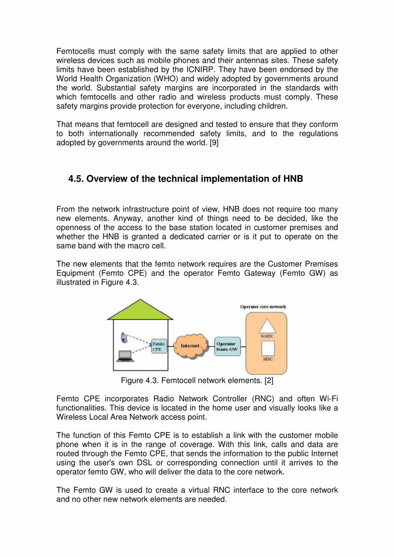
Femtocells must comply with the same safety limits that are applied to other wireless devices such as mobile phones and their antennas sites. These safety limits have been established by the ICNIRP. They have been endorsed by the World Health Organization (WHO) and widely adopted by governments around the world. Substantial safety margins are incorporated in the standards with which femtocells and other radio and wireless products must comply. These safety margins provide protection for everyone, including children. That means that femtocell are designed and tested to ensure that they conform to both internationally recommended safety limits, and to the regulations adopted by governments around the world. [9]
4.5. Overview of the technical implementation of HNB
From the network infrastructure point of view, HNB does not require too many new elements. Anyway, another kind of things need to be decided, like the openness of the access to the base station located in customer premises and whether the HNB is granted a dedicated carrier or is it put to operate on the same band with the macro cell. The new elements that the femto network requires are the Customer Premises Equipment (Femto CPE) and the operator Femto Gateway (Femto GW) as illustrated in Figure 4.3.
Figure 4.3. Femtocell network elements. [2]
Femto CPE incorporates Radio Network Controller (RNC) and often Wi-Fi functionalities. This device is located in the home user and visually looks like a Wireless Local Area Network access point. The function of this Femto CPE is to establish a link with the customer mobile phone when it is in the range of coverage. With this link, calls and data are routed through the Femto CPE, that sends the information to the public Internet using the user's own DSL or corresponding connection until it arrives to the operator femto GW, who will deliver the data to the core network. The Femto GW is used to create a virtual RNC interface to the core network and no other new network elements are needed.

CHAPTER 4. FEMTOCELL / HOME BASE STATIONS 47
About the openness of the access, there are two different options; a closed access femtocell has a fixed set of subscribed home users (for privacy and security) that are licensed to use the device. On the other hand, open access femtocells provide service to macrocell users when the pass nearby. Although open access reduces the macrocell load, the higher numbers of users communicating with each femtocell will strain the backhaul to provide enough capacity and raise privacy concerns for users. Open access will need to allow connection for the paying home user always. Since femtocells are typically marketed as offering flat-rate calling, open access will need to differentiate between the zero-tariff home users from the pay-per-minute visitor. For both reasons, operators are looking at hybrid models where some of the femtocell’s resources are reserved for registered family members, while others are open for roamers. [1], [3], [49]
4.5.1. Network implementations In a femtocell environment, the operator will need to provide a secure and scalable interface for the femtocell over IP, at a reasonable cost. Traditional Radio Network Controllers (RNCs) are equipped to handle tens to hundreds of macrocells. To provide equal parity service to femtocells over internet four different 3G femtocells architectures have been proposed:
- Iu-b over IP – The architecture in Figure 4.4 is based on existing 3G networks, with each femtocell connecting to the RNC over the standard 3GPP Iub interface. The Iub protocol stack is encapsulated within the IP signalling, also called a tunnelling lub. Network security is handled by the IP security (IPsec) protocol. The main concern with this approach is the ability of the RNC to scale to servicing tens of thousands of Node-Bs. This and the fact that (despite it being a standard interface) the Iub typically has vendor specific features, making this approach only suitable for equipment manufacturers with an installed RNC base.

Figure 4.4. Tunnelling Iub with modified RNC. [7]
- Concentrator – To overcome the concerns with conforming to
proprietary Iub interfaces and getting current RNCs to handle thousands of Node-Bs, Figure 4.5 presents an alternative architecture that uses a proprietary Concentrator/RNC that can handle thousands of Node-Bs. This approach allows functions to be partitioned differently between the Node-B and RNC enabling the concentrator to handle multiple Node-BS. This approach fits seamlessly into mobile network operator's RAN by replacing their current RNCs with this proprietary concentrator to service thousands of Femtocells.

CHAPTER 4. FEMTOCELL / HOME BASE STATIONS 49
Figure 4.5. Proprietary Concentrator/RNC. [7]
- UMA – UMA is at the forefront of many FMC solutions. The approach to
integrating this technology into an existing network is to place UMA Access Network (UMAN) alongside the existing Radio Access Network (RAN). The interface into the existing Core Network is through the UMA Network Controller (UNC), which is the equivalent to the 3G RNC. UMA-enabled handsets communicate through a Wi-Fi access point across an existing broadband connection to the UNC. IP tunnelling techniques are used to transparently extend all circuit and packet-based services. Figure 4.6 shows how this can be extended to home base stations, or femtocells. The UMA client function moves into de femtocell allowing any standard 2G/3G phone to communicate with the network through the UMAN. The advantage here is that this technology is now standardised and is designed for integrating millions of end-user devices into the mobile network. Since this architecture removes the RNC, the functionality associated with this is moved into the base station (RLC/RRC tasks to support radio channel set up, etc). As such, the femtocell is now more intelligent or autonomous and is often re-named as an “Access Point”. These tasks are significantly simpler than those required in a traditional RNC; for example, given the constrained environment of a femtocell, support for mobility is simpler, there is no need for soft-handoff, etc. This architecture is often referred to as “flattened”, “collapsed stack” or “Base Station Router”.

Incidentally, the use of this UMA architecture applies to the licensed band. In recognition of this, UMA is starting to be redefined as “universal” mobile access.
Figure 4.6. UMA Enable Femtocell [7]
- IMS & SIPS – Figure 4.7 shows another approach that breaks from the
existing network architecture and embraces the protocols of an all-IP network as envisaged by the 3GPP IP Multimedia Subsystem (IMS). These include Voice over IP (VoIP) using the Session Initiated Protocol (SIP), with the RNC function fully now integrated into the femtocell. Parenthetically, this architecture is more aligned with the WiMAX architecture, which is IP-based from the start. [1], [3], [7], [8]

CHAPTER 4. FEMTOCELL / HOME BASE STATIONS 51
Figure 4.7. SIP/IMS Enabled Femtocell. [7]
4.6. Interference in Femtocell deployment Managing radio frequency interference is an integral part of the mobile network simply because there are not sufficient frequency channels and unique codes available. Frequency and code reuse is carefully controlled as part of the network plan, balancing the capacity needs in each coverage area with the availability of channels and the amount of interference that can be tolerated. The effect of femtocells on the macro network is a major concern. These networks cannot scale to support hundreds of thousands of femtocells because they use manual network planning processes. That means femtocells must be self-provisioning. The low output power of femtocells helps to minimise their impact in the overlaying macro network. The lower output of the handsets connected to the femtocell will also reduce levels of interference, as well as the drain on batteries. The attenuation through walls which is a problem for in-building coverage turns into a benefit as they keep interference inside the building. But still being an interference problem. Femtocells will have to automatically adapt their power output to prevailing macro network radio conditions. This is critical to the performance of both the
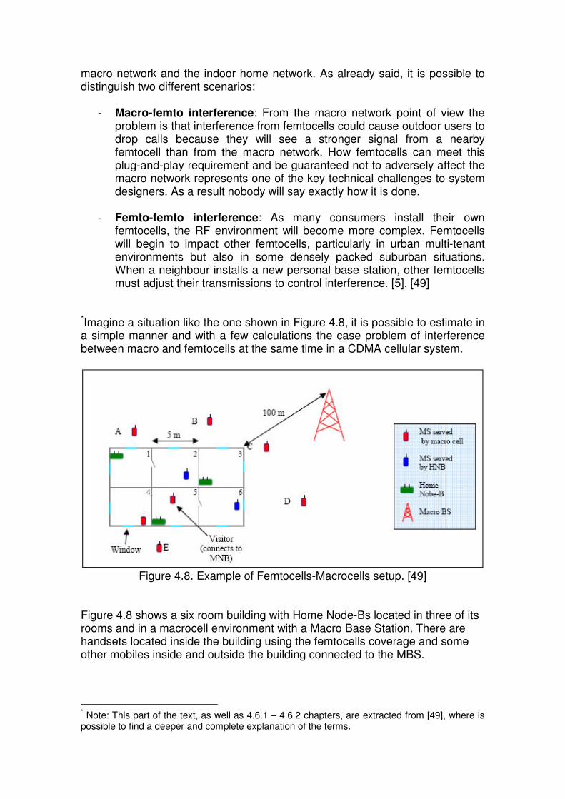
macro network and the indoor home network. As already said, it is possible to distinguish two different scenarios:
- Macro-femto interference: From the macro network point of view the problem is that interference from femtocells could cause outdoor users to drop calls because they will see a stronger signal from a nearby femtocell than from the macro network. How femtocells can meet this plug-and-play requirement and be guaranteed not to adversely affect the macro network represents one of the key technical challenges to system designers. As a result nobody will say exactly how it is done.
- Femto-femto interference: As many consumers install their own
femtocells, the RF environment will become more complex. Femtocells will begin to impact other femtocells, particularly in urban multi-tenant environments but also in some densely packed suburban situations. When a neighbour installs a new personal base station, other femtocells must adjust their transmissions to control interference. [5], [49]
*Imagine a situation like the one shown in Figure 4.8, it is possible to estimate in a simple manner and with a few calculations the case problem of interference between macro and femtocells at the same time in a CDMA cellular system.
Figure 4.8. Example of Femtocells-Macrocells setup. [49]
Figure 4.8 shows a six room building with Home Node-Bs located in three of its rooms and in a macrocell environment with a Macro Base Station. There are handsets located inside the building using the femtocells coverage and some other mobiles inside and outside the building connected to the MBS.
* Note: This part of the text, as well as 4.6.1 – 4.6.2 chapters, are extracted from [49], where is possible to find a deeper and complete explanation of the terms.

CHAPTER 4. FEMTOCELL / HOME BASE STATIONS 53
The users and Home Node-Bs inside the building are named with the same number of the room where they are located, i.e. user 6 is the user in room 6. Users outside the building are alphabetically ordered A…E. The next interference analysis is not to be considered extensive, its intent is simply to illustrate simplify the quantity and the magnitude of the problems related to HNB concept and their possible solutions. To make even simpler, additional losses such as cellular phone body losses, cable losses, etc. are not included in the equations. The analysis is based on the assumptions given in Table 4.1.
Carrier frequency 2.0 GHz Service 384 kbps data Phone transmit power Max 21 dBm HNB transmit power Max 24 dBm MNB transmit power Max 43 dBm MNB antenna gain 12 dBi HNB antenna gain 5 dBi Outer wall attenuation 15 dB Inner wall attenuation 8 dB Inside wall attenuation 5 dB Wall with window attenuation 10 dB Distance MNB-building 50 m Room size 5 m x 5 m
Table 4.1. Interference analysis assumptions. [49]
The Table 4.2 shows the distance between users and base stations in meters. MNB HNB1 HNB3 HNB5 User 2 50 10 2 7 User 4 50 12 8 2 User 5 50 8 4 3 User 6 50 15 5 10 User A 60 3 10 13 User B 50 13 8 16 User C 40 18 10 17 User D 30 25 15 18 User E 65 16 9 3
Table 4.2. Distance between users in Figure 4.8. [49]
The power received by a user is expressed using a simple link budget formula:
othershadowingpathotherantrxanttxtr LLLGGGPP −−−+++= .,., (4.1)
, where

Pr = total received signal power, Pt = transmitted power, Gtx,ant. = gain of the transmit antenna, Gtx,ant. = gain of the receive antenna, Gother = other gains (such as spreading gain), Lpath = path loss, Lshadowing = loss due to shadow fading, Lother = other, such as wall, cable and feeder losses. The path loss component in (1) could be approximately estimated by the free space attenuation formula:
( ) ( )
++=
=
=
cfd
c
df
c
dfLpath
πππ 4log20log20log20
4log20
4log10 10101010
2
10
( ) ( ) ( ) ( ) 44,32log20log2056,147log20log20 10101010 ++=−+= MHzkm fdfd
, and if GHzfMHz 2= ,
( ) 46,98log20 10 += kmpath dL (4.2)
The following analysis tries to study the two more critical cases. For simplicity, it is first assumed that all the base stations are transmitting at full power (MNB 43 dBm and HNB 24 dBm). [49]
4.6.1. Interference case 1: User in room 6 connected to HNB in room 5
The user in room 6 receives interference from the Macro Node B and the two other home Node Bs. The situation is showed in Figure 4.9.

CHAPTER 4. FEMTOCELL / HOME BASE STATIONS 55
Figure 4.9. Interference case 1 setup. [49]
The power interference could be simply calculated:
)( 6,.,,int windowMSMNBpathantMNBMNBterference LLGPP −−+=−
)*2( 61,.,1, insidewallinnerwallMSHNBpathantHNBHNBt LLLGP −−−++−
)L-L-G(P innerwallMS6-HNB3path,ant.HNB,HNB3t, ++
dB) 5– dB 98,46) log(0,05)*(20– dB 12 dBm 43( ++=
dB) 5 * 2– dB 8– dB 98,46) log(0,015)*(20– dB 5 dBm (24 +++
dB) 8– dB 98,46) log(0,005)*(20– dB 5 dBm (24 +++
dBm) (-31,44 dBm) (-50,98 dBm 22,44- ++=
≈ 0,005702 mW + 7,98 nW + 0,718 µW ≈ 6,427 µW
≈ -21,92 dBm (4.3)
If the HNB in room 5 is transmitting at full power (24 dBm), user in room 6 (about 10 meters from HNB in room 5) receives a signal having power approximately:
PGLLGPP insidewallfreespaceHNBHNBtuserr +−−+= ,6, (4.4)
, where PG is the processing gain in W-CDMA system calculates as:
=
=
)/(
/84,3log10log10 1010
sbutratedatauser
sMchip
ratedatauser
ratechipWCDMAPG (4.5)
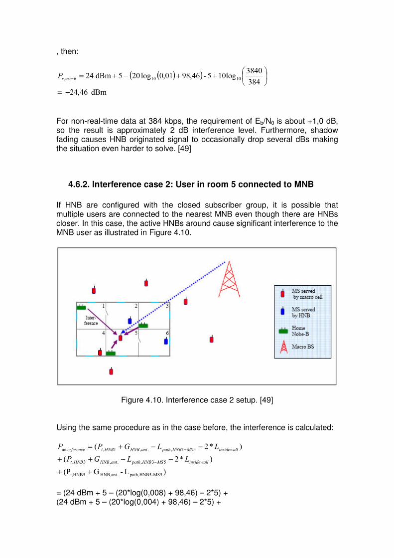
, then:
( )( )
++−+=
384
384010log5-46,9801,0log205dBm24 10106,userrP
dBm46,24−=
For non-real-time data at 384 kbps, the requirement of Eb/N0 is about +1,0 dB, so the result is approximately 2 dB interference level. Furthermore, shadow fading causes HNB originated signal to occasionally drop several dBs making the situation even harder to solve. [49]
4.6.2. Interference case 2: User in room 5 connected to MNB If HNB are configured with the closed subscriber group, it is possible that multiple users are connected to the nearest MNB even though there are HNBs closer. In this case, the active HNBs around cause significant interference to the MNB user as illustrated in Figure 4.10.
Figure 4.10. Interference case 2 setup. [49]
Using the same procedure as in the case before, the interference is calculated:
)*2( 51,.,1,int insidewallMSHNBpathantHNBHNBterference LLGPP −−+=−
)*2( 53,.,3, insidewallMSHNBpathantHNBHNBt LLGP −−++−
)L-G(P MS5-HNB5path,ant.HNB,HNB5t, ++
= (24 dBm + 5 – (20*log(0,008) + 98,46) – 2*5) + (24 dBm + 5 – (20*log(0,004) + 98,46) – 2*5) +

CHAPTER 4. FEMTOCELL / HOME BASE STATIONS 57
(24 dBm + 5 – (20*log(0,003) + 98,46)) = (–37,52 dBm) + (–31,50 dBm) + (–19,00 dBm) = – 18,91 dBm (4.6) And the received signal power is now:
PGLLLGPP innerwallouterwallfreespaceGMNBMNBtuserr +−−−+= *2,6,
= 43 dBm + 12 – (20log(0,05) + 98,46) – 15 – 2*8 dB + 10log(3840/384) = – 38,44 dBm (4.7)
In this case, the average SINR experienced by the user 5 is more or less -19,53 dB, which is clearly below adequate for receiving 384 kbit/s. [49]
4.6.3. Adaptive antennas and dynamic spectrum management The chapters 4.6.1 – 4.6.2 illustrated that interference in HNB deployment is a critical issue. However, there are several techniques that have been considered for reducing interference. Two of them could be the utilization of adaptative antennas and dynamic spectrum management in a femtocell situation.
- Adaptative Antennas - The spectral efficiency is always one prominent thing in interference problems. It is possible to say that the success and efficiency of a wireless system depends on the spectral efficiency. One of the methods to achieve high spectral efficiency is the Adaptive Antenna System (AAS). AAS provides gain and interference mitigation leading to improved signal quality and spectral efficiency. This system consist of multiple antenna elements at the transmitting and/or receiving side of the communication link, whose signals are processed adaptively in order to exploit the spatial dimension of the mobile radio channel. Depending on whether the processing is performed at the transmitter, receiver, or both ends of the communication link, the adaptive antenna technique is defined as multiple-input single-output (MISO), single-input multiple-output (SIMO), or multiple-input multiple-output (MIMO). An Adaptive Antenna System (AAS) can focus its transmit energy to the direction of a receiver. While receiving, it can focus to the direction of the transmitting device. Combined with multiple antennas in the Base Station (BS), AAS can be used to serve multiple Subscriber Stations (SSs) with higher throughput. A technique known as SDMA (Space Division Multiple Access) is employed here where multiple SSs that are separated (in space) can transmit and receive at the same time over the same sub-channel. AAS also eliminates interference to and from other SSs and other sources by steering the nulls to the direction of interferers. AAS is feature suits very well for LTE and it is an optional feature in WiMAX as it yet to
be included in WiMAX certification. MIMO spatial link adaptation enables a femtocell to switch between providing high data rates and robust transmission. High data rates are obtainable by transmitting multiple spatial streams over high SINR links. Over low SINR links, MIMO provides robustness through open and closed loop diversity schemes.
- Dynamic Spectrum Management - The concept of dynamic spectrum
management or also known as cognitive radio refers to the capacity of either a network or a wireless node to change its transmission or reception parameters (in the case of femtocells, the frequency) to communicate efficiently avoiding interference in load networks. Cognitive radio is believed to be a technology with a high potential to achieve the efficiency use of the spectrum. Systems using cognitive radio are capable of reconfiguring themselves based on the surrounding environments and their own properties with respect to traffic load, congestion, situation, network topology, wireless channel propagation etc. In the case of femtocell, cognitive radio can be used in spectrum management capturing the best available spectrum to meet user communication requirements. The system decides on the best spectrum band to meet the Quality of Service requirements over all available spectrum bands. [2], [47], [48], [49]

CHAPTER 5. CONCLUSIONS 59
CHAPTER 5. CONCLUSIONS Technology development in recent decades has enabled wireless technologies to become essential in the field of telecommunications. The continuing growth in demand has led to a constant evolution in such systems, finding for each issue, a viable solution to satisfy the user. Currently there is a new barrier. Cellular systems on which mobile phones are based are not enough prepared to cover the demand concerned in terms of new technologies. The widespread use of these systems does not allow users to enjoy a service tailored to the new technologies, introducing problems of coverage and speed especially in indoor environments. To fix this problem, the use of femtocells could become an indispensable tool. Taking advantage of a technology widely used, such as DSL technology or similar services, femtocells have the ability to backhaul voice and data services from a user handset through the online Internet connection, permitting a macrocell receive fewer loads of users and allowing subscribers benefits such:
- Improved indoor coverage - Raising connection speeds - Voice quality enhance - Getting rates or services at lower price - Achieve greater efficiency in the use of batteries
For operators, the use of femtocells also leads benefits. Basically, it allows them to offer services according to the demand without having to invest huge amounts in modifications of the actual system (macrocell system) that has become obsolete for development of 3G and future 4G in mobile usages. In this way, operators can offer cheaper services and allows them a better preparation and anticipation of the newcomer technologies. But perhaps the biggest problem with this technology is the interference. Because femtocells are low power devices, firstly should not present interference problems, but at the time that these devices will mass commercialize in macrocellular environments, different cases of interference will be presented. The reason is that femtocells work on the same frequencies that macrocellular systems do and situations can arise where a mobile connection to either the MBS or the HNB can be interfered with the closer elements. To try to solve these problems, operators and distributors focus on the use of adaptative antennas and dynamic spectrum management, with a greater efficiency of the already overloaded spectrum could be achieve and furthermore, the connection using femtocells could be possible.

GLOSSARY 3G: Third Generation 3GPP: Third Generation Partnership Project 3GPP2: Third Generation Partnership Project 2 AAS: Adaptative Antenna System AFH: Adaptative Frequency-Hoping AM: Amplitude Modulation AMPS: Advanced Mobile hone System ARIB: Association of Radio, Industries and Business AUC: Authentication Center BSC: Base Station Controller BSS: Base Station Subsystem BTS: Base Transceiver Station Capex: Capital Expenses CCSA: China Communications Standards Association CDMA: Code Division Multiple Access CEPT: European Conference of Postal and Telecommunications administrators CMOS: Complementary Metal-Oxide-Semiconductor CN: Core Network CT: Cordless Telephone DAB: Digital Audio Broadcasting DQPSK: Differential Quadrature Phase Shift Keying EDGE/EGPRS: Enhanced Data rates for GSM Evolution / Enhanced GPRS EDR: Enhanced Data Rate EIR: Equipment Identify Register ETSI: European Telecommunications Standards Institute FCC: Federal Communications Commission FDD: Frequency Division Duplex FM: Frequency Modulation FMC: Fixed Mobile Convergence GGSN: GPRS Getaway Support Node GMSK: Gaussian Minimum Shift-Keying GPRS: General Packet Radio Services GPS: Global Positioning System GSM: Groupe Spécial Mobile Hi-Fi: High Fidelity HLR: Home Location Register HTML: HyperText Markup Language ICNIRP: International Commission on Non-Ionising Radiation Protection IEEE: Institute of Electrical and Electronics Engineers IMEI: International Mobile Equipment Identify IMSI: International Mobile Subscriber Identify IP: Internet Protocol IPsec: Internet Protocol Security ITU: International Telecommunication Union LAI: Location Area Identifier LAN: Local Area Network MIMO: Multiple-Input Multiple-Output MISO: Multple-Input Single-Output MRP: Market Representation Partners MSC: Mobile Switching Center MSISDN: Mobile Station Integrated Services Digital Network MSRN: Mobile Station Roaming Number NGMN: Next Generation Mobile Network NMT: Nordic Mobile Telephone NSS: Network and Switching Subsystem NSS: Network and Switching System OFDM: Orthogonal Frequency Division Multiplexing

GLOSSARY 61
Opex: Operating Expenses PAN: Personal Area Network PCM: Pulse Code Modulation PCU: Packet Control Unit PMR/LMR: Private Mobile Radio / Land Mobile Radio PRN: Pseudo-Random Noise PSTN: Public Switched Telephone Network QoS: Quality of Service RF: Radio-Frequency RNC: Radio Network Controller RNS: Radio Network Subsystem RPE-LTP: Regular Press Excited – Long Term Prediction SDMA: Space Division Multiple Access SDO: Standard Development Organization SGSN: Serving GPRS Support Node SIG: Special Interest Group SIM: Subscriber Identify Module SIMO: Single-Input Multiple-Output SINTEF: Independent Research Organization Group in Scandinavia SMS: Short Message Service SMSC: Short Message Service Center SS: Subscriber Station TCP: Transmission Control Protocol TDCDMA: Time Division CDMA TDD: Time Division Duplex TDMA: Time Division Multiple Access TIA: Telecommunication Industry Association TMSI: Temporal Mobile Subscriber Identity TRAU: Transcoder and Rate Adaptation Unit TSG: Technical Specification Group TTA: Telecommunication Technology Association UE: User Equipment UMTS: Universal Mobile Telecommunication System UPnP: Universal Plug’n’Play USIM: User Service Identity Module UTRAN: Universal Terrestrial Radio Access Network UWB: Ultra-Wide-Band VLR: Visitor Location Register VoIP: Voice over Internet Protocol WAP: Wireless Application Protocol W-CDMA: Wideband – CDMA WHO: World Health Organization WiMAX: Worldwide interoperability for Microwave Access WLAN: Wireless Local Area Network WPAN: Wireless Personal Area Network

BIBLIOGRAPHY [1] Roberta Wiggins. Femtocells: Driving a New Network Design Philosophy. Yankee Group, July 2007. [2] Mika Husso, Jyri Hämäläinen, Riku Jäntti, Alexander M. Wyglinski. Adaptative Antennas and Dynamic Spectrum Management for Femtocellular Networks: A Case Study. [3] Unstrung Insider. 3G Home Base Stations: Femto Cells & FMC for the Masses. January 2007. [4] Vikram Chandrasekhar, Jeffrey G. Andrews, Alan Gatherer. Femtocell Networks: A Survey. The University of Texas at Austin, Texas Instruments. June 2008. [5] Airvana. Femto Cells: Personal Base Stations. [6] Nokia Siemens Networks. Striding toward an open market with the 3G Femto Home Access Solution. 2007 [7] picoChip. The case for Home Base Stations: Technical White Paper. April 2007 [8] Kineto Wireless. UMA: The 3GPP Standard for Femtocell-to-Core Network Connectivity. August 2007. [9] Mobile Manufacturers Forum, GSMA, Femto Forum. Femtocells and Health. [10] intrado, next point. Connecting when it counts: The role of femtocells in emergency calls. [11] Aricent. Challenges in Deployment of UMTS/HSPA Femtocell. February 2008. [12] Nokia Siemens Network. Reaching the mass market with 3G Femto Home Access. 2007. [13] ip.access. Femtocells: The business case. http://www.ipaccess.com/femtocells/business_case.php [14] Todd Merchs. Mass Femtocell Deployment and the RF Environment. Continuous Computing. February 2008. http://www.rfdesignline.com/showArticle.jhtml?articleID=206801563 [15] Manish Singh. Top ten challenges to Femtocell deployment. Continuous Computing. March 2008. http://www.embedded.com/design/206905482 [16] Answers.com. Femtocells. http://www.answers.com/topic/femtocell

BIBLIOGRAPHY 63
[17] Wikipedia.org. Radio (medio de comunicación). http://es.wikipedia.org/wiki/Radio_(medio_de_comunicaci%C3%B3n) [18] Tapan K. Sarkar, Robert J. Mailloux, Arthur A. Oliner, Magdalena Salazar-Palma, Dipak L. Sengputa. History of Wireless. Wiley-IEEE, 2006. [19] Lewis Coe. Wireless Radio: A Brief History. McFarland, 1996. [20] Andrea Goldsmith. Wireless Communications. Cambridge University Press, 2005. [21] Wikipedia.org. Ethernet. http://en.wikipedia.org/wiki/Ethernet [22] Wikipedia.org. GSM. http://en.wikipedia.org/wiki/GSM [23] Wikipedia.org. Wi-Fi. http://en.wikipedia.org/wiki/Wi-Fi#History [24] Wikipedia.org. Amateur radio. http://en.wikipedia.org/wiki/Amateur_radio [25] Wikipedia.org. Professional Mobile Radio. http://en.wikipedia.org/wiki/Professional_Mobile_Radio [26] Wikipedia.org. Trunked Radio System. http://en.wikipedia.org/wiki/Trunked_radio_system [27] Wikipedia.org. DVB. http://es.wikipedia.org/wiki/DVB [28] Oriol Sallent Roig, VV Staff, José Luis Valenzuela González, Ramon Agustí Comes. Principios de Comunicaciones Móviles. Edicions UPC, 2003. [29] José María Hernando Rábanos. Comunicaciones Móviles. Ramón Areces, 2004. [30] Wikipedia.org. International Mobile Equipment Identity. http://en.wikipedia.org/wiki/IMEI [31] Wikipedia.org. General Packet Radio System. http://en.wikipedia.org/wiki/General_Packet_Radio_Service [32] Wikipedia.org. Enhanced Data Rates for GSM Evolution. http://es.wikipedia.org/wiki/EDGE [33] Peter Stuckmann. The GSM Evolution: Traffic Engineering for Packet Data Services. John Wiley and Sons, 2002. [34] Maria Carmen España Boquera. Servicios Avanzados de Telecomunicación. Ediciones Díaz de Santos, 2003.

[35] Rajami Ganesh, Kaveh Pahlavan, Zoran Zvonar. Wireless multimedia network technologies. Springer, 2000. [36] Wikipedia.org. Universal Mobile Telecommunication System. http://es.wikipedia.org/wiki/Comunicaciones_UMTS [37] Wikipedia.org. Ultra-wideband. http://en.wikipedia.org/wiki/Ultra-wideband [38] Wikipedia.org. 802.11. http://en.wikipedia.org/wiki/802.11 [39] Wikipedia.org. Wireless LAN. http://en.wikipedia.org/wiki/Wireless_LAN [40] Femto Forum webpage. http://www.femtoforum.org/femto/index.php?id=46 [41] ip.access webpage. http://www.ipaccess.com/femtocells/femtocells.php [42] broadband forum webpage. http://www.broadband-forum.org/index.php [43] 3GPP webpage. http://www.3gpp.org/about-3gpp [44] 3GPP2 webpage. http://www.3gpp2.org/Public_html/Misc/AboutHome.cfm [45] next generation mobile networks webpage. http://www.ngmn.org/nc/de/home.html [46] GSM Association webpage. http://www.gsmworld.com/about-us/index.htm [47] Wikipedia.org. Cognitive Radio. http://en.wikipedia.org/wiki/Cognitive_radio [48] 3G and 4G Wireless Blog. Adaptative Antenna System. http://3g4g.blogspot.com/2008/07/adaptive-antenna-system.html [49] Mika Husso. Technical and Economic Challenges in Femto Cell Deployment.


![MAQUETA 1:200 - CORE · 2016. 11. 8. · MAQUETA 1:200 MAQUETA $OXPQH )UDQFLVFR 7RUR *yPH]7XWRU /OXtV 7REHOOD )DUUDQ24 Casal de barri de la Trinitat Nova PFC Juny 2016 (VFROD 7qFQLFD](https://static.fdocumento.com/doc/165x107/613f944cf0f55d448e4ce2fa/maqueta-1200-core-2016-11-8-maqueta-1200-maqueta-oxpqh-udqflvfr-7rur.jpg)
![TFC[Tiempo Frecuencia]](https://static.fdocumento.com/doc/165x107/55cf8c6a5503462b138c21e5/tfctiempo-frecuencia.jpg)