UNIVERSAL TESTING MACHINE Final Version - … pdf... · Revista Mexicana de Física 2010 (Aceptado)...
13
Revista Mexicana de Física 2010 (Aceptado) 1 UNIVERSAL TESTING MACHINE FOR MECHANICAL PROPERTIES OF THIN MATERIALS E. Huerta * , J.E. Corona, A.I. Oliva Centro de Investigación y de Estudios Avanzados del IPN Unidad Mérida, Departamento de Física Aplicada. AP. 73 -Cordemex, 97310 Mérida Yucatán, México. E-mail: [email protected] F. Avilés Centro de Investigación Científica de Yucatán A.C., Unidad de Materiales. Calle 43 No. 130 Col. Chuburná de Hidalgo, 97200, Mérida Yucatán México. Jesús González Centro de Investigación en Materiales Avanzados, S.C. Av. Miguel de Cervantes 120 Complejo Industrial Chihuahua, 31109 Chihuahua, Chihuahua, México. Abstract In this work, the design, construction, calibration and compliance measurement of a universal testing machine for tension tests of materials in film geometry are presented. A commercial load cell of 220 N and sensitivity of 1.2345 mV/V is used to measure the tension applied load. Material strain is measured by movement of the cross-head displacement of the machine with a digital indicator with 0.001 mm resolution and 25 mm maximum displacement, connected to a PC through an interface. Mechanical strain is achieved by an electric high precision stepper motor capable to obtain displacement velocities as low as 0.001 mm/s. The stress- strain data acquired with a GPIB interface are saved as a file with a home-made program developed in LabView 7.0. Measurements of the elastic modulus and yield point of a commercial polymer film (500HN Kapton) were used to calibrate the performance of the testing machine. The obtained mechanical properties are in good agreement with the mean values reported by the supplier, taking into account the limitations of thin film testing and that experimental conditions do not fully agree with the ASTM standards. * Doctoral student at CIMAV-Chihuahua, México
Transcript of UNIVERSAL TESTING MACHINE Final Version - … pdf... · Revista Mexicana de Física 2010 (Aceptado)...
Revista Mexicana de Física 2010 (Aceptado)
1
UNIVERSAL TESTING MACHINE FOR MECHANICAL PROPERTIES OF THIN
MATERIALS
E. Huerta*, J.E. Corona, A.I. Oliva
Centro de Investigación y de Estudios Avanzados del IPN Unidad Mérida, Departamento de
Física Aplicada. AP. 73 -Cordemex, 97310 Mérida Yucatán, México.
E-mail: [email protected]
F. Avilés
Centro de Investigación Científica de Yucatán A.C., Unidad de Materiales. Calle 43 No. 130
Col. Chuburná de Hidalgo, 97200, Mérida Yucatán México.
Jesús González
Centro de Investigación en Materiales Avanzados, S.C. Av. Miguel de Cervantes 120
Complejo Industrial Chihuahua, 31109 Chihuahua, Chihuahua, México.
Abstract
In this work, the design, construction, calibration and compliance measurement of a universal
testing machine for tension tests of materials in film geometry are presented. A commercial
load cell of 220 N and sensitivity of 1.2345 mV/V is used to measure the tension applied load.
Material strain is measured by movement of the cross-head displacement of the machine with
a digital indicator with 0.001 mm resolution and 25 mm maximum displacement, connected
to a PC through an interface. Mechanical strain is achieved by an electric high precision
stepper motor capable to obtain displacement velocities as low as 0.001 mm/s. The stress-
strain data acquired with a GPIB interface are saved as a file with a home-made program
developed in LabView 7.0. Measurements of the elastic modulus and yield point of a
commercial polymer film (500HN Kapton) were used to calibrate the performance of the
testing machine. The obtained mechanical properties are in good agreement with the mean
values reported by the supplier, taking into account the limitations of thin film testing and that
experimental conditions do not fully agree with the ASTM standards.
* Doctoral student at CIMAV-Chihuahua, México
Revista Mexicana de Física 2010 (Aceptado)
2
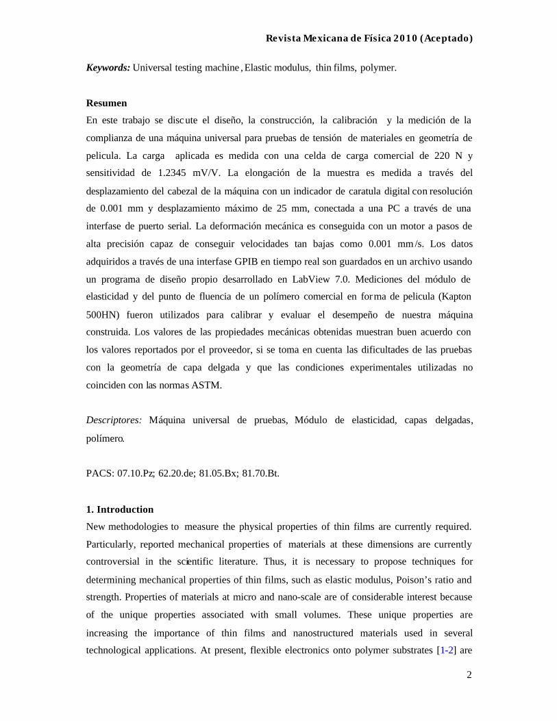
Keywords: Universal testing machine , Elastic modulus, thin films, polymer.
Resumen
En este trabajo se discute el diseño, la construcción, la calibración y la medición de la
complianza de una máquina universal para pruebas de tensión de materiales en geometría de
pelicula. La carga aplicada es medida con una celda de carga comercial de 220 N y
sensitividad de 1.2345 mV/V. La elongación de la muestra es medida a través del
desplazamiento del cabezal de la máquina con un indicador de caratula digital con resolución
de 0.001 mm y desplazamiento máximo de 25 mm, conectada a una PC a través de una
interfase de puerto serial. La deformación mecánica es conseguida con un motor a pasos de
alta precisión capaz de conseguir velocidades tan bajas como 0.001 mm /s. Los datos
adquiridos a través de una interfase GPIB en tiempo real son guardados en un archivo usando
un programa de diseño propio desarrollado en LabView 7.0. Mediciones del módulo de
elasticidad y del punto de fluencia de un polímero comercial en forma de pelicula (Kapton
500HN) fueron utilizados para calibrar y evaluar el desempeño de nuestra máquina
construida. Los valores de las propiedades mecánicas obtenidas muestran buen acuerdo con
los valores reportados por el proveedor, si se toma en cuenta las dificultades de las pruebas
con la geometría de capa delgada y que las condiciones experimentales utilizadas no
coinciden con las normas ASTM.
Descriptores: Máquina universal de pruebas, Módulo de elasticidad, capas delgadas,
polímero.
PACS: 07.10.Pz; 62.20.de; 81.05.Bx; 81.70.Bt.
1. Introduction
New methodologies to measure the physical properties of thin films are currently required.
Particularly, reported mechanical properties of materials at these dimensions are currently
controversial in the scientific literature. Thus, it is necessary to propose techniques for
determining mechanical properties of thin films, such as elastic modulus, Poison’s ratio and
strength. Properties of materials at micro and nano-scale are of considerable interest because
of the unique properties associated with small volumes. These unique properties are
increasing the importance of thin films and nanostructured materials used in several
technological applications. At present, flexible electronics onto polymer substrates [1-2] are
Revista Mexicana de Física 2010 (Aceptado)
3
being developed for many applications, such as electronic textiles [3] and paper-like displays
[4-5]. These electronic devices are normally subjected to high external stresses and large
strains due to the flexible material used as substrate [6]. As it is well known, the film
properties can be quite different from the bulk properties [7]. Thus, knowledge of the
mechanical properties of nanostructured materials is of primordial importance to obtain
functional and reliable electronic devices. Different methods have been proposed to
investigate the mechanical properties of these thin materials. The most common methods are
based on X-ray diffraction [8], interferometry [9] and most recently, nanoindentation [10-11].
These methods often require sophisticated instrumentation and do not compel with the
conventional definition of mechanical properties, which are defined in terms of conventional
tensile testing. In bulk geometry, the mechanical properties are commonly obtained through
tensile testing, and there exists different commercial machines for characterization of bulk
materials [12-15]. Tensile testing is an effective way to investigate the mechanical properties
of material and it is a well established technique for bulk sample characterization. However,
tensile testing is not easily implemented for micro and nano-structured materials due to the
small dimensions of the specimen. At present, there exist these testing machines for materials
in film geometry [16-18] but they are expensive and its flexib ility to make modifications is
limited. In this wor k, the design, construction, calibration and compliance determination of a
universal testing machine specially designed for tensile tests of materials in film geometry is
discussed. Our universal testing machine is designed to produce small deformations at low
velocities and, consequently, high resolution. The testing machine is sensitive to small loads,
and permits to obtain the stress-strain curves for materials in film geometry. Elastic modulus,
yield point, and maximum stress can be obtained from samples of up to about 10 cm length.
An important feature of this device is the simplicity to exchange components according to the
user requirements, the low cost, low machine compliance and the high resolution obtained.
This machine can also be adapted for compression testing with appropriate samples and grips.
However, compression testing will not be addressed in this work.
2. Design and construction
The testing machine was designed to determine the stress-strain curves of thin materials such
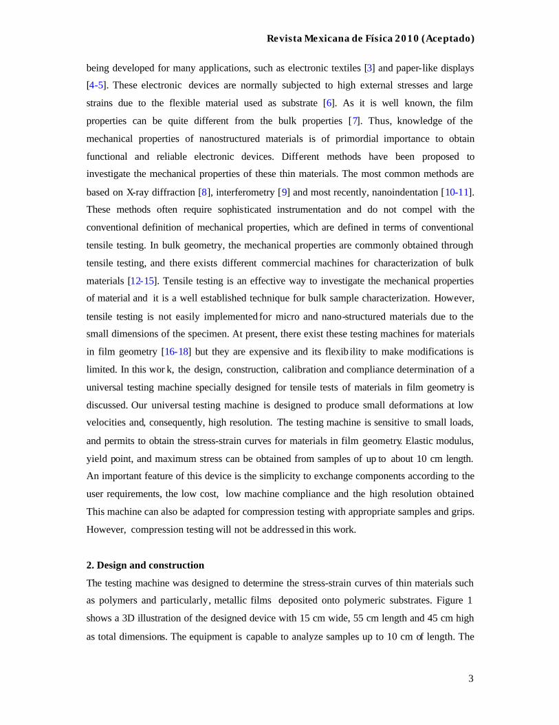
as polymers and particularly, metallic films deposited onto polymeric substrates. Figure 1
shows a 3D illustration of the designed device with 15 cm wide, 55 cm length and 45 cm high
as total dimensions. The equipment is capable to analyze samples up to 10 cm of length. The
Revista Mexicana de Física 2010 (Aceptado)
4
mechanical design minimizes effects of load introduction in the main frame, drive screws, and
the relative movement between the movable crosshead and the drive screws.
FIGURE 1. 3D view of the universal testing machine.
As is shown in Figure 1, the testing machine is composed of five main parts: i) the main
frame, ii) the drive system, iii) the movable crosshead, iv) the load cell, and v) the digital
indicator. The testing machine is mainly made of stainless steel, excepting for some frictional
elements like the gears, which were made of bronze.
The main frame includes the rectangular base where the gearbox is placed, the fixed
crosshead and the two vertical parallel columns. The drive system includes a stepper motor
with variable speed. The gearbox is formed by a worm shaft, and two worm gears, which
moves the two drive screws. The movable crosshead is integrated by the bottom grip, two
conical fastener tools with internal thread and an adjustable conical ring. The conical fastener
tools provide stabilization to the movable crosshead when moving along the drive screws.
The load cell used is a LCC-HTC-50 dual stud cell from Load Cell Central Co. [19] which
withstands a 220 N maximum load with a sensitivity of 1.2345 mV/V. The load cell can be
used for tension or compression testing, is located on the upper side of the frame and supports
the upper grip. The digital indicator measures the crosshead displacement and it consists of a
digital micrometer from Starret [20] with 0.001 mm of resolution, which is connected with a
RS232 interface to a personal computer to acquire data.
To achieve high resolution in the measurements, the device includes a stepper motor used to
control both velocity and torque. The drive system achieves displacements as small as 0.001
mm and velocities between 0.001 mm/s and 0.1 mm/s. Two stainless-stee l grips (one fixed to
the load cell and the other on the movable crosshead) are used to hold the samples. The grips
Revista Mexicana de Física 2010 (Aceptado)
5
were designed with smooth surfaces to avoid damage to the soft and thin samples. Each grip
is composed by a fixed part and a movable plate joined with two screws to uniformly press
the samples. This system avoids sliding between sample and grid during tensile tests. The
design of this universal testing machine permits to interchange the different parts such as the
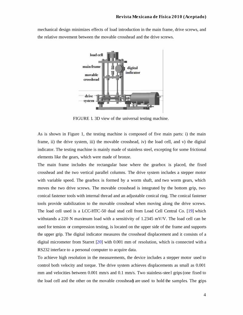
load cell, grips and drive screws, in order to extend the user requirements. Figure 2 shows a
photograph of the universal testing machine. Stress-strain data are captured and saved in a
data file through a GPIB interface controlled with a home-made protocol programmed in
LabView 7.0.
FIGURE 2. Photograph of the universal testing machine. The different components shown in
Figure 1 such as the drive system, load cell, electronic indicator, movable crosshead and
stepper motor can be observed.
3. Performance.
In order to determine the performance of the proposed testing machine, following the work
done to calibrate the load cell, the methodology used to obtain the compliance of the machine,
and the data acquisition are discussed.
3.1. Calibration and data acquisition.
The calibration of the load cell was conducted by collecting data of different known applied
loads (weights) and measuring its corresponding output voltage.
Calibration measurements were conducted by steps over a range of 0 to 12 N with a n elapsed-
time of 1 min between each calibrated load, in order to avoid hysteretic effects; i.e, the
voltage returns to cero value after removing the load. A series of calibrated loads were applied
in increasing order. The output voltage of the load cell was captured through a high-resolution
Revista Mexicana de Física 2010 (Aceptado)
6
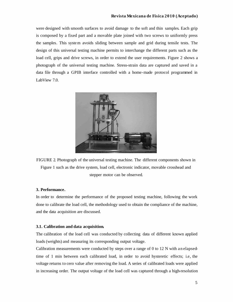
programmable voltmeter HP 3458A. Figure 3 shows the obtained linear behavior between the
applied load (P) and the output voltage (V) as obtained from the load cell. The equation
describing this relationship can be expressed by:
P =12.8366 V- 0.06574 (1)
where the applied load P is given in Newtons and the output voltage V, in milivolts.
This linear behavior confirms the information provided by the manufacturer and permits to
obtain a relationship to be used into the program as transduction signal.
FIGURE 3. Calibration curve showing the relation between applied load and the voltage
response of the load cell.
According to the supplier, the load cell can support maximum loads of 220 N, but it is not
desirable to reach this limit given that supplier guarantees a linear deviation of 0.15% at full
load.
The data acquisition system uses a GPIB interface of National instruments to control the
applied excitation voltage of the power supply and to collect the corresponding output voltage
of the voltmeter. The GPIB interface is controlled with a home-made program developed in
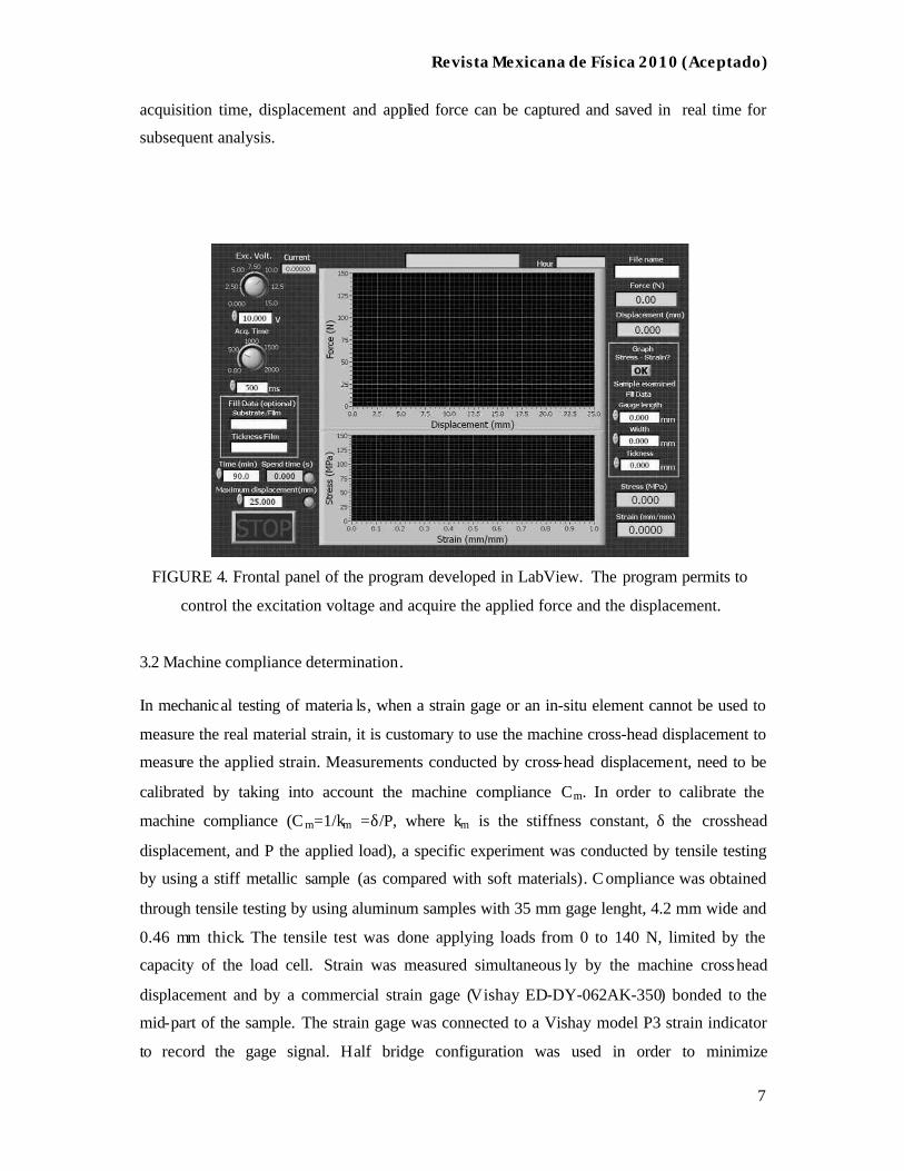
Labview 7.0. Figure 4 shows the frontal panel of the implemented program and the different
parameters used to obtain the stress-strain curve. The designed program permits to select the
acquisition time, step-time, and the excitation voltage for the load cell, and requires the
length, width and thickness of samples as entries. The force-displacement and stress-strain
curves are plotted in real time during testing. Using this program, parameters as data
Revista Mexicana de Física 2010 (Aceptado)
7
acquisition time, displacement and applied force can be captured and saved in real time for
subsequent analysis.
FIGURE 4. Frontal panel of the program developed in LabView. The program permits to
control the excitation voltage and acquire the applied force and the displacement.
3.2 Machine compliance determination.
In mechanical testing of materia ls, when a strain gage or an in-situ element cannot be used to
measure the real material strain, it is customary to use the machine cross-head displacement to
measure the applied strain. Measurements conducted by cross-head displacement, need to be
calibrated by taking into account the machine compliance Cm. In order to calibrate the
machine compliance (C m=1/km =δ/P, where km is the stiffness constant, δ the crosshead
displacement, and P the applied load), a specific experiment was conducted by tensile testing
by using a stiff metallic sample (as compared with soft materials). C ompliance was obtained
through tensile testing by using aluminum samples with 35 mm gage lenght, 4.2 mm wide and
0.46 mm thick. The tensile test was done applying loads from 0 to 140 N, limited by the
capacity of the load cell. Strain was measured simultaneous ly by the machine crosshead
displacement and by a commercial strain gage (Vishay ED-DY-062AK-350) bonded to the
mid-part of the sample. The strain gage was connected to a Vishay model P3 strain indicator
to record the gage signal. Half bridge configuration was used in order to minimize
Revista Mexicana de Física 2010 (Aceptado)
8
temperature effects. The total compliance measured by the crosshead displacement (CT) is a
sum of the compliance of the analyzed material (CAl) and the compliance of the machine
(Cm), simulating a series spring system. Since CT and CAl are measured during the
experiment, the machine compliance can be determined by the relation:
CT=Cm+CAl (2)
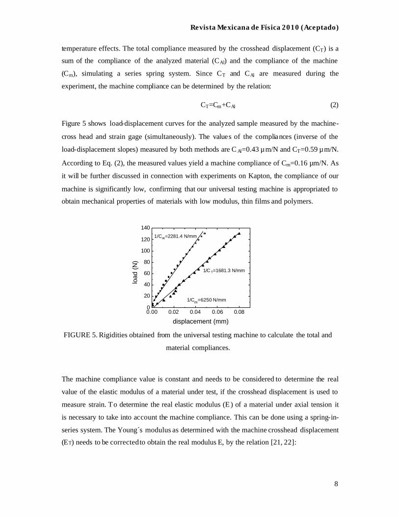
Figure 5 shows load-displacement curves for the analyzed sample measured by the machine-
cross head and strain gage (simultaneously). The values of the compliances (inverse of the
load-displacement slopes) measured by both methods are C Al=0.43 µm/N and CT=0.59 µm/N.
According to Eq. (2), the measured values yield a machine compliance of Cm=0.16 µm/N. As
it will be further discussed in connection with experiments on Kapton, the compliance of our
machine is significantly low, confirming that our universal testing machine is appropriated to
obtain mechanical properties of materials with low modulus, thin films and polymers.
0.00 0.02 0.04 0.06 0.080
20
40
60
80
100
120
140
load
(N
)
displacement (mm)
1/C T=1681.3 N/mm
1/CAl=2281.4 N/mm
1/Cm=6250 N/mm
FIGURE 5. Rigidities obtained from the universal testing machine to calculate the total and
material compliances.
The machine compliance value is constant and needs to be considered to determine the real
value of the elastic modulus of a material under test, if the crosshead displacement is used to
measure strain. To determine the real elastic modulus (E ) of a material under axial tension it
is necessary to take into account the machine compliance. This can be done using a spring-in-
series system. The Young´s modulus as determined with the machine crosshead displacement
(ET) needs to be corrected to obtain the real modulus E, by the relation [21, 22]:
Revista Mexicana de Física 2010 (Aceptado)
9
LAEC
EE
Tm
T
−=
1 (3)
Where Cm is the measured machine compliance, A the sectional area, and L the gage length.
4. Results and validation.
A commercial polymer, 500HN Kapton, was initially used as a benchmarking specimen by its
well-known properties reported by the DuPont Co. supplier [23]. Tensile tests were conducted
using rectangular geometries of Kapton films of 40 mm length, 5 mm wide and 0.125 mm
thick. The gage length of the samples was always 20 mm. The displacement velocity of the
movable crosshead during tensile experiments was maintained at 0.01 mm/s in all cases.
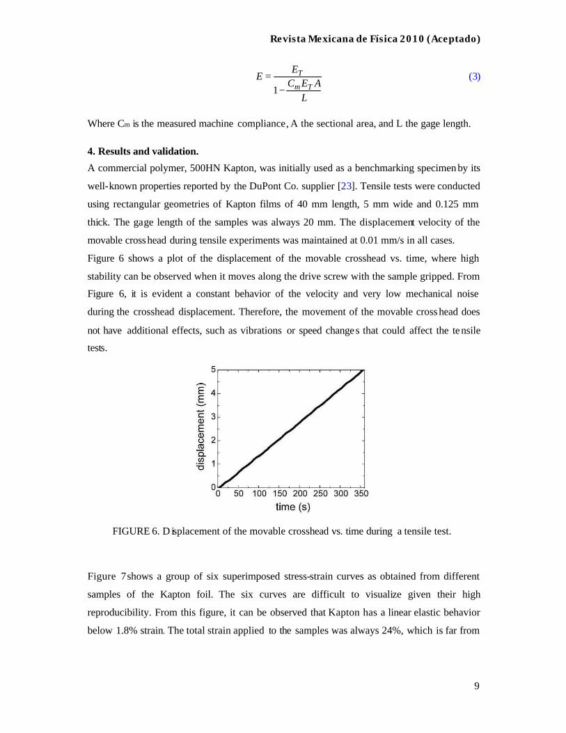
Figure 6 shows a plot of the displacement of the movable crosshead vs. time, where high
stability can be observed when it moves along the drive screw with the sample gripped. From
Figure 6, it is evident a constant behavior of the velocity and very low mechanical noise
during the crosshead displacement. Therefore, the movement of the movable cross head does
not have additional effects, such as vibrations or speed changes that could affect the tensile
tests.
FIGURE 6. D isplacement of the movable crosshead vs. time during a tensile test.
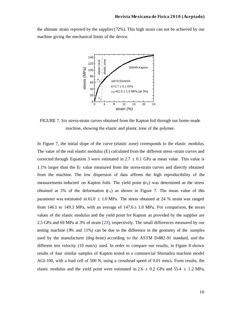
Figure 7 shows a group of six superimposed stress-strain curves as obtained from different
samples of the Kapton foil. The six curves are difficult to visualize given their high
reproducibility. From this figure, it can be observed that Kapton has a linear elastic behavior
below 1.8% strain. The total strain applied to the samples was always 24%, which is far from
Revista Mexicana de Física 2010 (Aceptado)
10
the ultimate strain reported by the supplier (72%). This high strain can not be achieved by our
machine giving the mechanical limits of the device.
0 4 8 12 16 20 240
20
40
60
80
100
120
140
vel=0.01mm/s
stre
ss (
MP
a)
strain (%)
εY
σY
plas
tic z
one
elas
tic z
one
500HN Kapton
σY=61.0 ± 1.0 MPa (at 3%)
E=2.7 ± 0.1 GPa
FIGURE 7. Six stress-strain curves obtained from the Kapton foil through our home-made
machine, showing the elastic and plastic zone of the polymer.
In Figure 7, the initial slope of the curve (elastic zone) corresponds to the elastic modulus.
The value of the real elastic modulus (E) calculated from the different stress -strain curves and
corrected through Equation 3 were estimated in 2.7 ± 0.1 GPa as mean value . This value is
1.1% larger than the ET value measured from the stress-strain curves and directly obtained
from the machine. The low dispersion of data affirms the high reproducibility of the
measurements inducted on Kapton foils. The yield point (σY) was determined as the stress
obtained at 3% of the deformation (εY) as shown in Figure 7. The mean value of this
parameter was estimated in 61.0 ± 1.0 MPa. The stress obtained at 24 % strain was ranged
from 146.1 to 149.3 MPa, with an average of 147.6 ± 1.0 MPa. For comparison, the mean
values of the elastic modulus and the yield point for Kapton as provided by the supplier are
2.5 GPa and 69 MPa at 3% of strain [23], respectively. The small differences measured by our
testing machine (9% and 11%) can be due to the difference in the geometry of the samples
used by the manufacturer (dog-bone) according to the ASTM D-882-91 standard, and the
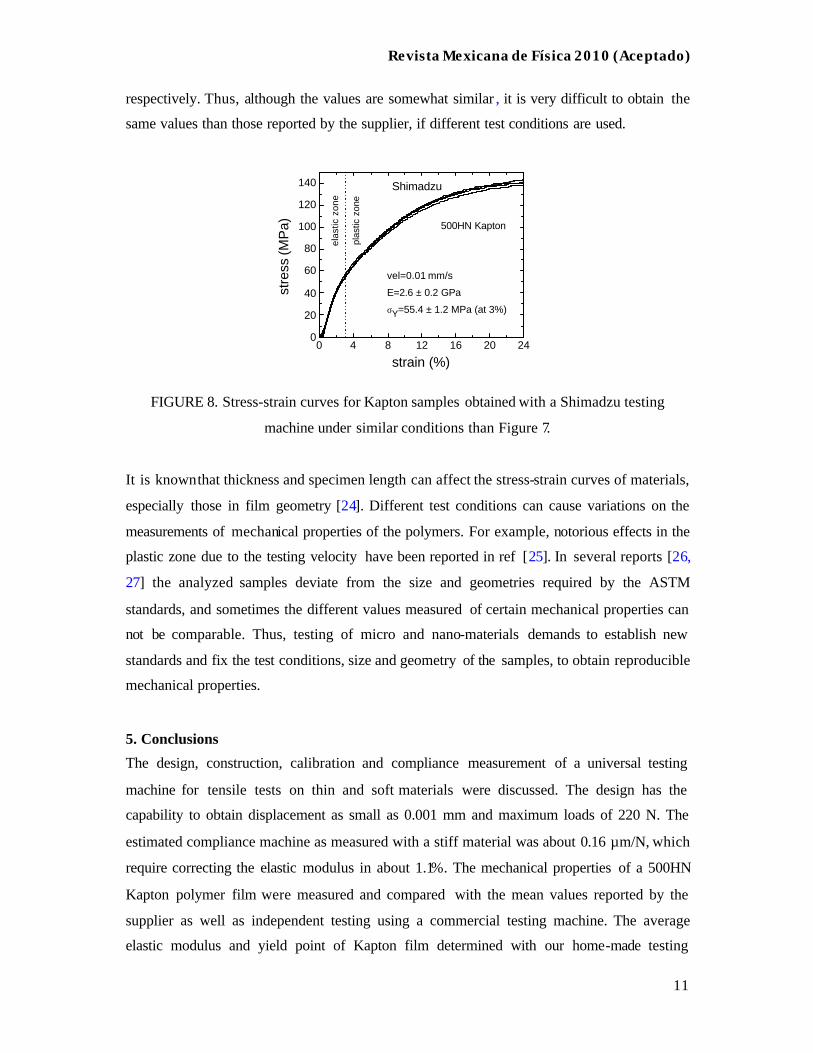
different test velocity (10 mm/s) used. In order to compare our results, in Figure 8 shown
results of four similar samples of Kapton tested in a commercial Shimadzu machine model
AGI-100, with a load cell of 500 N, using a crosshead speed of 0.01 mm/s. From results, the
elastic modulus and the yield point were estimated in 2.6 ± 0.2 GPa and 55.4 ± 1.2 MPa,
Revista Mexicana de Física 2010 (Aceptado)
11
respectively. Thus, although the values are somewhat similar , it is very difficult to obtain the
same values than those reported by the supplier, if different test conditions are used.
0 4 8 12 16 20 240
20
40
60
80
100
120
140
stre
ss (M
Pa)
strain (%)
Shimadzu
σY=55.4 ± 1.2 MPa (at 3%)
vel=0.01 mm/s
E=2.6 ± 0.2 GPa
500HN Kapton
elas
tic z
one
plas
tic z
one
FIGURE 8. Stress-strain curves for Kapton samples obtained with a Shimadzu testing
machine under similar conditions than Figure 7.
It is known that thickness and specimen length can affect the stress-strain curves of materials,
especially those in film geometry [24]. Different test conditions can cause variations on the
measurements of mechanical properties of the polymers. For example, notorious effects in the
plastic zone due to the testing velocity have been reported in ref [25]. In several reports [26,
27] the analyzed samples deviate from the size and geometries required by the ASTM
standards, and sometimes the different values measured of certain mechanical properties can
not be comparable. Thus, testing of micro and nano-materials demands to establish new
standards and fix the test conditions, size and geometry of the samples, to obtain reproducible
mechanical properties.
5. Conclusions
The design, construction, calibration and compliance measurement of a universal testing
machine for tensile tests on thin and soft materials were discussed. The design has the
capability to obtain displacement as small as 0.001 mm and maximum loads of 220 N. The
estimated compliance machine as measured with a stiff material was about 0.16 µm/N, which
require correcting the elastic modulus in about 1.1%. The mechanical properties of a 500HN
Kapton polymer film were measured and compared with the mean values reported by the
supplier as well as independent testing using a commercial testing machine. The average
elastic modulus and yield point of Kapton film determined with our home-made testing
Revista Mexicana de Física 2010 (Aceptado)
12
machine were 2.7 GPa, and 61.0 MPa, which were only slightly different as compared to the
mean values reported by the supplier and are also in reasonable agreement with independent
tensile testing. The performance and low compliance value of our testing machine indicate
that it is appropriate to obtain reliable mechanical properties of compliant materials in thin
and soft materials. Our testing machine permits to interchange different elements according to
the user requirements. An additional advantage of our testing machine is the lower cost and
smaller size compared to other commercial machines. Future efforts will address the use of
this equipment to obtain the mecha nical properties of thin metallic films (pure and alloys)
with different nano-thickness deposited on polymeric substrates.
Acknowledgements:
Authors recognize the technical assistance of Gaspar Euán and Oswaldo Gómez. This work
was financially supported by CONACYT - México through project F1-54173.
References
1. C.T. Huang. C.L. Shen, C.F. Tang, S.H. Chang, Sensors & Actuators A 141 (2008) 396.
2. S. A. Wilson, R. P. J. Jourdain, Q. Zhang, Mat. Sci. Eng. R 56 (2007) 1.
3. E. Bonderove, S. Wagner, IEEE Electr. Dev. Lett. 25 (2004) 295.
4. J. Rogers, Science 291 (2001) 1502.
5. Y. Chen, J. Au, P. Kazlas, A. Ritenour, H. Gates, M. McCreary, Nature 423 (2003) 136.
6. F. Macionczyk, W. Brückner, J. Appl. Phys. 86 (1999) 4922.
7. A.I. Oliva Arias, F. López Garduza, V. Sosa, Ingeniería 10 (2006) 57.
8. P. Goudeau, P.O. Renault, P. Villain, C. Coupeau, V. Pelosin, B. Boubeker, K.F. Badawi,
D. Thiaudiere, M. Gailhanou, Thin Solid Films 49 (2001) 398.
9. W.N. Sharpe, Jr., B. Yuan, R. L Edwards, J. Microelectromech Syst. 6 (1997) 193.
10. C.S. Oh, H.J. Lee, S.G. Ko, S.W. Kim, H. G. Ahn. Sensors & Actuators A 117 (2005)
151.
11. R. Saha, W. D. Nix, Acta Mater. 56 (2008) 1399.
12. P. C. Lehning Jr, US Patent 3203232 (1965).
13. W. T. Gloor, US Patent 3323357 (1967).
14. R. J. Simonelli, US Patent 5913246 (1999).
15. S. Bergs, F. Sweden, US Patent 6148676 (2000).
16. A.V. Sergueeva , J. Zhou, B.E. Meacham and D.J. Branagan, Mater. Sci. Eng. A 526
Revista Mexicana de Física 2010 (Aceptado)
13
(2008) 79.
17. K. Yang, Y . Ivanisenko, A. Caron, A. Chuvilin, L. Kurmanaeva, T. Scherer, R.Z. Valiev,
H.J. Fecht. Acta Mater. 58 (2010) 967.
18. O. Kulyasova, R.K. Islamgaliev, B. Mingler, M. Zehetbauer. Mat. Sci. Eng. A 503 (2009)
176.
19. Load Cells, Dual Stud Load Cell Tension/Compression Model: LCC-HTC,
http://www.800loadcel.com.
20. Starret, Athol, MA , US, Catalog No. 31B (2007) 192.
21. U. Ramamurty, A. Paul. Acta Mater. 52 (2004) 869.
22. N. Huber, Ch. Tsakmakis, J. Mater. Res. 13 (1998) 1650.
23. DuPont, Circleville, OH, US, Technical Data Sheet (1999) 1.
24. Y.H. Zhao, Y.Z. Guo, Q. Wei, A.M. Dangelewicz, C. Xu, Y.T. Zhu, T.G. Langdon, Y.Z.
Zhou, E.J. Lavernia, Scripta Mater. 59 (2008) 627.
25. Handbook of Polymer Testing, Edited by R. Brown (Rapra Technology, Shrewsbury,
Shropshire SY4 4NR, UK. (2002) 97.
26. K.M. Youssef, R.O. Scattergood, K.L. Murty, J.A. Horton, C.C. Koch. Appl. Phys. Lett.
87 (2005) 091904.
27. Y.H. Zhao, J.F. Bingert, X.Z. Liao, B.Z. Cui, K. Han, A.V. Serhueeva, A.K. Muhkerjee,
R.Z. Valiev, T.G. Langdon, Y.T. Zhu, Adv. Mater. 18 (2006) 2494.