


Idiomas
Páginas
Jurídico

© 2001 Cooper Bussmann, Inc.
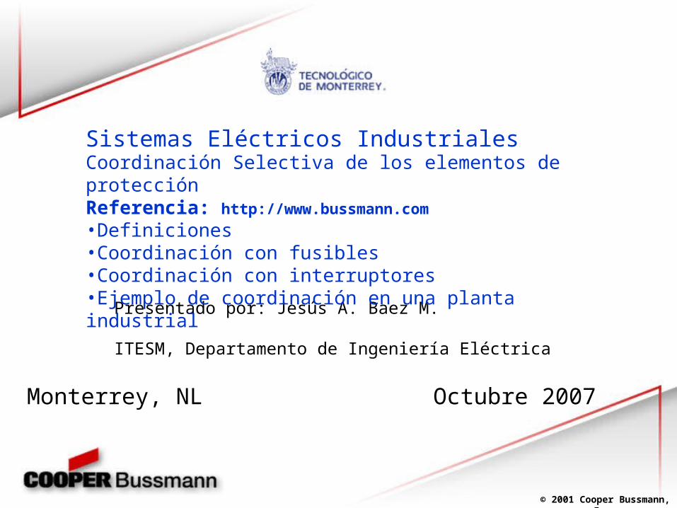
Presentado por: Jesús A. Baez M.
ITESM, Departamento de Ingeniería Eléctrica
Monterrey, NL Octubre 2007
Coordinación Selectiva de los elementos de protecciónReferencia: http://www.bussmann.com
•Definiciones•Coordinación con fusibles•Coordinación con interruptores•Ejemplo de coordinación en una planta industrial
Sistemas Eléctricos Industriales
© 2001 Cooper Bussmann, Inc.
Selective Coordination
Definition:
The act of isolating a faulted circuit from the remainder of the electrical system, thereby eliminating unnecessary power outages. The faulted circuit is isolated by the selective operation of only the overcurrent protective device closest to the overcurrent condition.
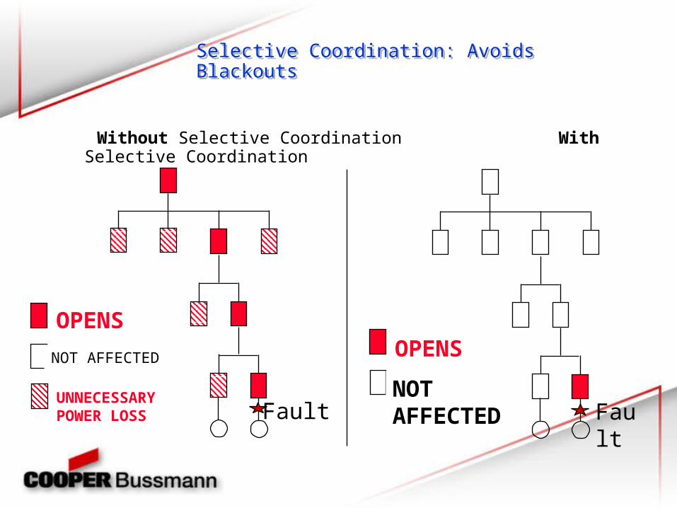
Without Selective Coordination With Selective Coordination
Selective Coordination: Avoids BlackoutsSelective Coordination: Avoids Blackouts
OPENS
NOT AFFECTED
UNNECESSARYPOWER LOSS
OPENS
NOT AFFECTEDFault Faul
t
© 2001 Cooper Bussmann, Inc.
Selective Coordination: NEC®
240.2 Definitions
Coordination.
The proper localization of a fault condition to restrict outages to the equipment affected, accomplished by the choice of selective fault-protective devices.
© 2001 Cooper Bussmann, Inc.
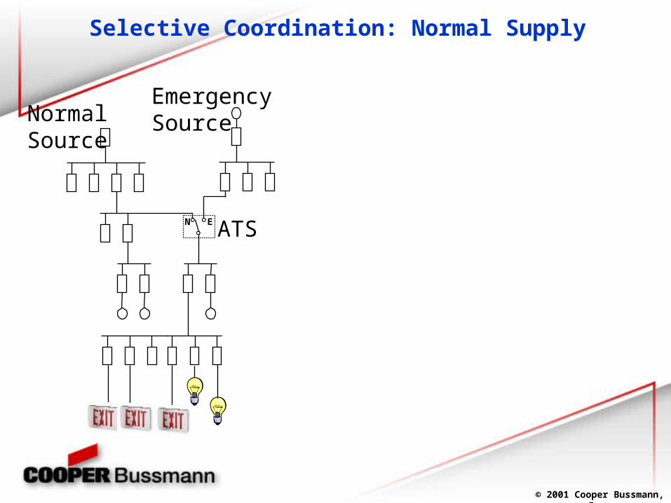
Selective Coordination: Normal Supply
ATS
EmergencySource
N E
NormalSource
© 2001 Cooper Bussmann, Inc.
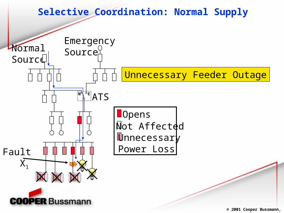
Selective Coordination: Normal Supply
Fault X1
ATS
EmergencySource
N E
NormalSource
OpensNot AffectedUnnecessaryPower Loss
Unnecessary Feeder Outage
© 2001 Cooper Bussmann, Inc.
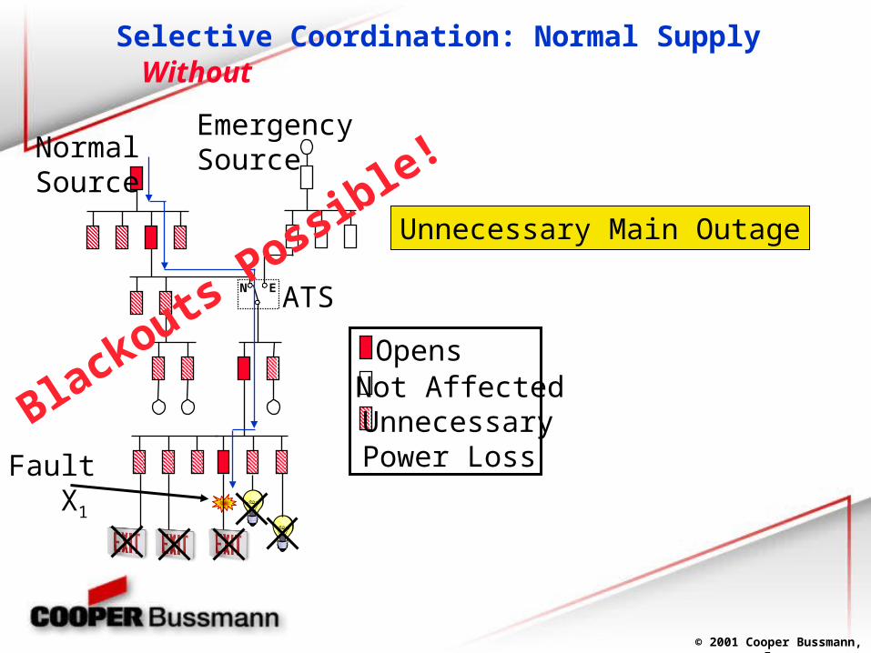
Selective Coordination: Normal Supply
Fault X1
ATS
EmergencySource
N E
NormalSource
OpensNot AffectedUnnecessaryPower Loss
Blackouts Possible!
Without
Unnecessary Main Outage
© 2001 Cooper Bussmann, Inc.
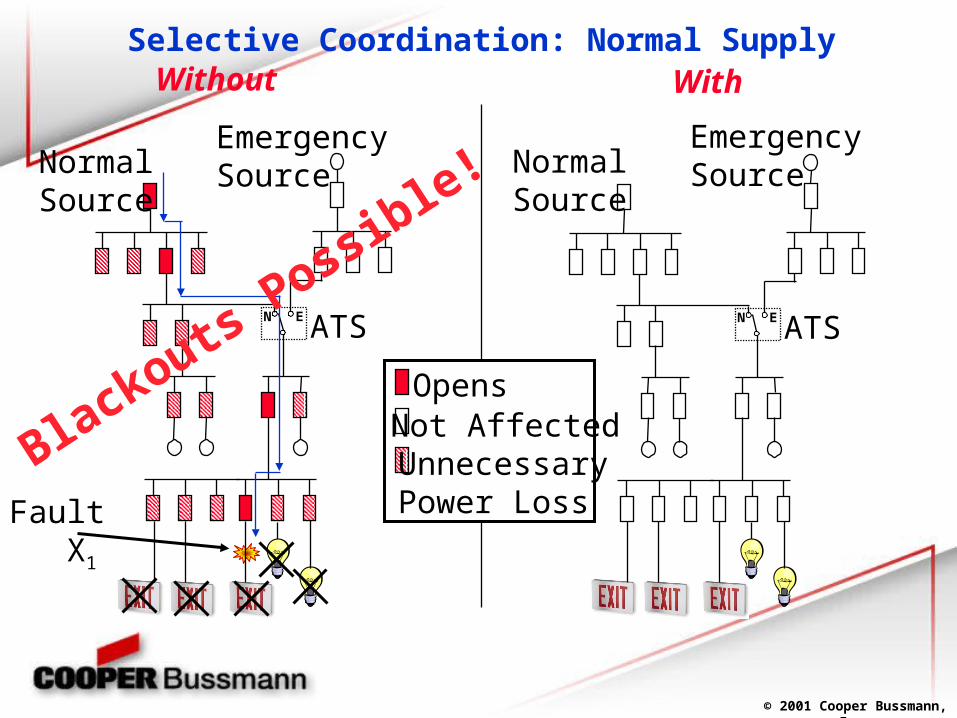
Selective Coordination: Normal Supply
Fault X1
ATS
EmergencySource
N E
NormalSource
ATSN E
OpensNot AffectedUnnecessaryPower Loss
EmergencySourceNormal
Source
Blackouts Possible!
Without With
© 2001 Cooper Bussmann, Inc.
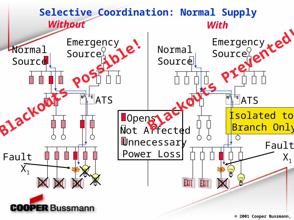
WithoutSelective Coordination: Normal Supply
Fault X1
ATS
EmergencySource
N E
NormalSource
ATSN E
OpensNot AffectedUnnecessaryPower Loss
With
Fault X1
EmergencySourceNormal
Source
Blackouts Prevented!
Blackouts Possible!
Isolated to Branch Only
© 2001 Cooper Bussmann, Inc.
Selective Coordination
Circuit Breaker Coordination
© 2001 Cooper Bussmann, Inc.
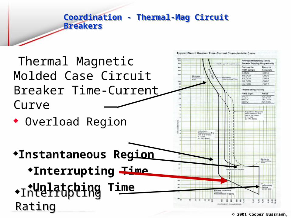
Coordination - Thermal-Mag Circuit BreakersCoordination - Thermal-Mag Circuit Breakers
Thermal Magnetic Molded Case Circuit Breaker Time-Current Curve Overload Region
Instantaneous RegionInterrupting TimeUnlatching Time
Interrupting RatingInterrupting Rating
© 2001 Cooper Bussmann, Inc.
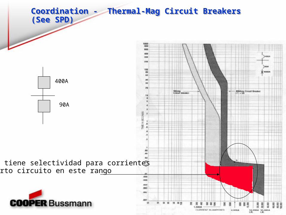
Coordination - Thermal-Mag Circuit Breakers (See SPD)Coordination - Thermal-Mag Circuit Breakers (See SPD)
No se tiene selectividad para corrientes de corto circuito en este rango
400A
90A
© 2001 Cooper Bussmann, Inc.
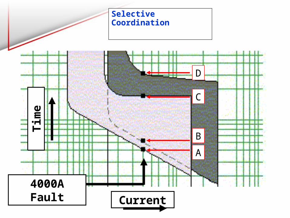
Selective Coordination
Current
Tim
e
A
B
C
D
4000A Fault

© 2001 Cooper Bussmann, Inc.
OPENS
NOT AFFECTED
UNNECESSARYPOWER LOSS Fault
Lacking Coordination

© 2001 Cooper Bussmann, Inc.
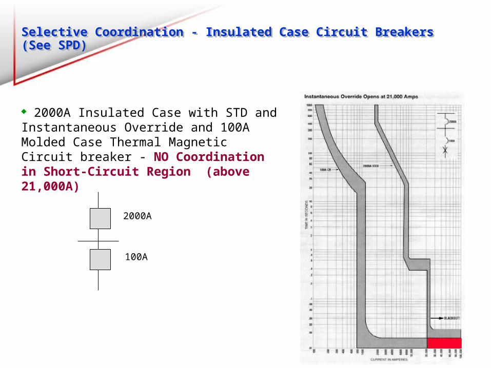
Selective Coordination - Insulated Case Circuit Breakers (See SPD)Selective Coordination - Insulated Case Circuit Breakers (See SPD)
2000A Insulated Case Circuit Breaker STD Is an Option - Allows breaker to delay opening Instantaneous Override built-in: may be as low as 12X the breaker rating Will often result in lack of coordination
© 2001 Cooper Bussmann, Inc.
Selective Coordination - Insulated Case Circuit Breakers (See SPD)Selective Coordination - Insulated Case Circuit Breakers (See SPD)
2000A Insulated Case with STD and Instantaneous Override and 100A Molded Case Thermal Magnetic Circuit breaker - NO Coordination in Short-Circuit Region (above 21,000A)
2000A
100A
© 2001 Cooper Bussmann, Inc.
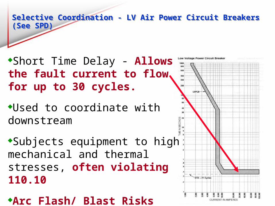
Selective Coordination - LV Air Power Circuit Breakers (See SPD)Selective Coordination - LV Air Power Circuit Breakers (See SPD)
Short Time Delay - Allows the fault current to flow for up to 30 cycles.
Used to coordinate with downstream
Subjects equipment to high mechanical and thermal stresses, often violating 110.10
Arc Flash/ Blast Risks Much Higher
High Cost, Larger Equipment

© 2001 Cooper Bussmann, Inc.
Selective Coordination: Fuses

© 2001 Cooper Bussmann, Inc.
Time Current Curves
Selective Coordination:Fuses (See SPD)

© 2001 Cooper Bussmann, Inc.
Selectivity Ratio
Guide Based on
Thermal Principle
Based on I2t Clear Clear
Not MeltNot Melt
I2t melting > I2t Clearing 1200 A 600 A
Selective Coordination:Fuses (See SPD)
© 2001 Cooper Bussmann, Inc.
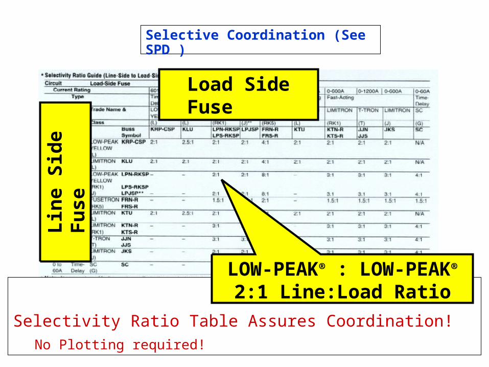
Selective Coordination (See SPD )
Selectivity Ratio Table Assures Coordination!No Plotting required!
LOW-PEAK® : LOW-PEAK®
2:1 Line:Load Ratio
Lin
e S
ide
Fu
se
Load Side Fuse
© 2001 Cooper Bussmann, Inc.
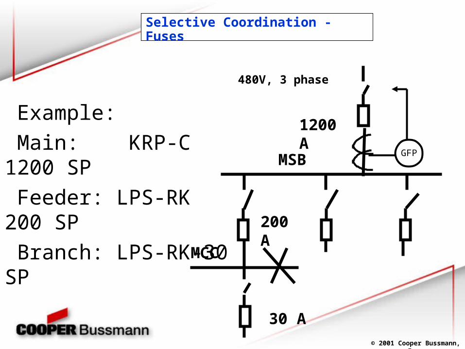
Example:
Main: KRP-C 1200 SP
Feeder: LPS-RK 200 SP
Branch: LPS-RK-30 SP
MSB
1200 A
200 A
30 A
480V, 3 phase
MCC
GFP
Selective Coordination - Fuses
© 2001 Cooper Bussmann, Inc.
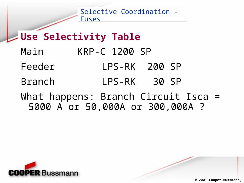
Selective Coordination - Fuses
Use Selectivity Table
Main KRP-C 1200 SP
Feeder LPS-RK 200 SP
Branch LPS-RK 30 SP
What happens: Branch Circuit Isca = 5000 A or 50,000A or 300,000A ?

© 2001 Cooper Bussmann, Inc.
Lineside KRP-C 1200SP to Loadside LPS-RK 200SP
1200/200 = 6:1 Table only need 2:1 Selective Coordination
Lineside LPS-RK 200SP to Loadside LPS-RK 30SP
200/30= 6.67:1 Table only need 2:1
Selective Coordination
Selective Coordination- Fuses
© 2001 Cooper Bussmann, Inc.
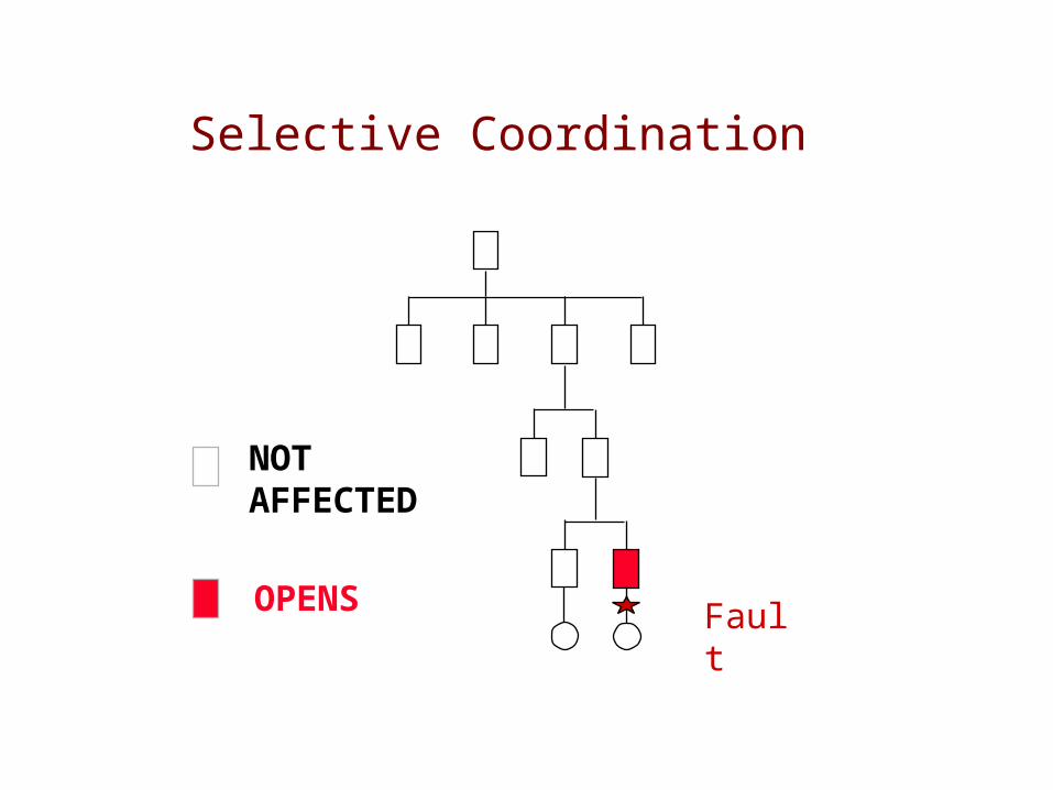
Fault
NOT AFFECTED
OPENS
Selective Coordination
© 2001 Cooper Bussmann, Inc.
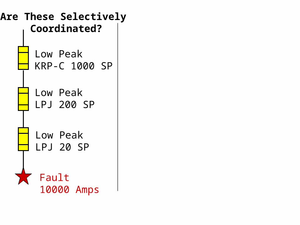
Fault 10000 Amps
Low PeakKRP-C 1000 SP
Low PeakLPJ 200 SP
Low PeakLPJ 20 SP
Are These Selectively Coordinated?

© 2001 Cooper Bussmann, Inc.
Fault 10000 Amps
Low PeakKRP-C 1000 SP
Low PeakLPJ 200 SP
Low PeakLPJ 20 SP
Are These Selectively Coordinated?
OPENS
NOT AFFECTED
Fault 10000 Amps
Low PeakKRP-C 1000 SP
Low PeakLPJ 200 SP
Low PeakLPJ 20 SP
Selectively Coordinated
© 2001 Cooper Bussmann, Inc.
Are These Selectively Coordinated?
Fault 10000 Amps
1000 A. CBIT @ 10 X
200 A. CBIT @ 10 X
20 A. CBIT @ 10X

© 2001 Cooper Bussmann, Inc.
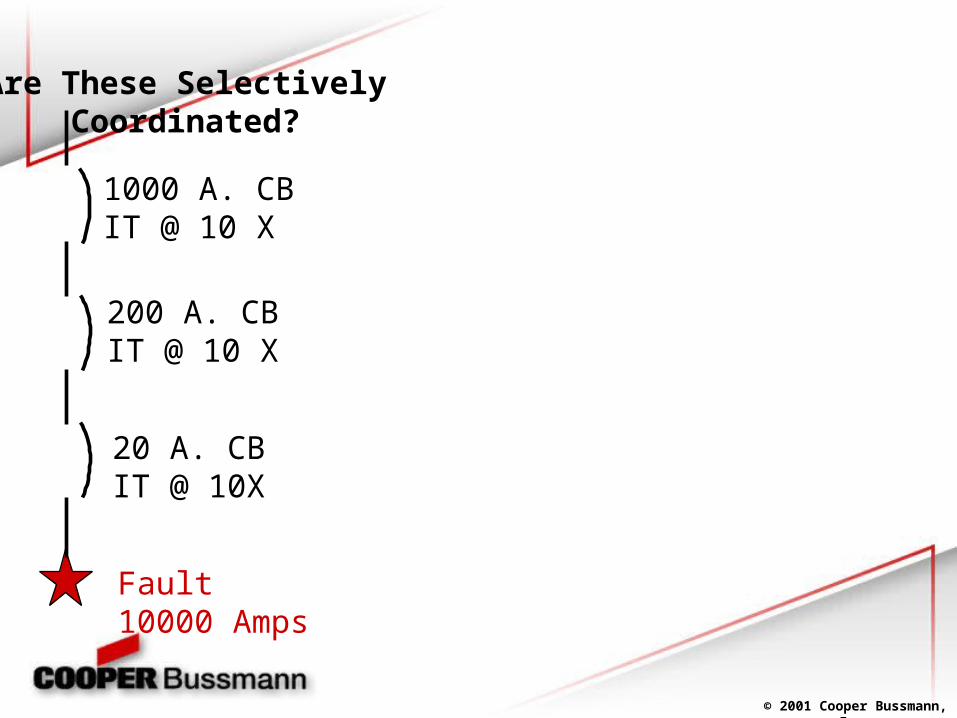
Are These Selectively Coordinated?
Fault 10000 Amps
1000 A. CBIT @ 10 X
200 A. CBIT @ 10 X
20 A. CBIT @ 10X
Not Coordinated
OPENS
NOT AFFECTED
Fault 10000 Amps
1000 A. CBIT @ 10 X
200 A. CBIT @ 10 X
20 A. CBIT @ 10X
© 2001 Cooper Bussmann, Inc.
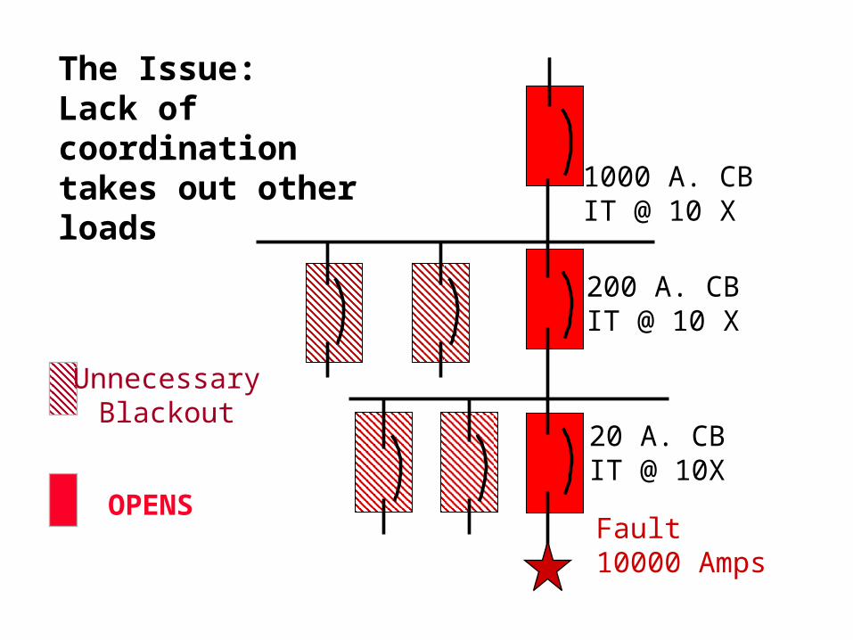
UnnecessaryBlackout
The Issue:Lack of coordinationtakes out other loads
OPENSFault 10000 Amps
1000 A. CBIT @ 10 X
200 A. CBIT @ 10 X
20 A. CBIT @ 10X

© 2001 Cooper Bussmann, Inc.
Ejemplo de coordinación mostrando protección de los cables