DYNAMIC MODELING AND CONTROL OF QUADROTOR VEHICLE
5
DYNAMIC MODELING AND CONTROL OF QUADROTOR VEHICLE A. Y. Elruby M. M. El-khatib N. H. El-Amary A. I. Hashad Arab Academy for science and Technology, Egypt Egyptian Armed Force, Egypt Arab Academy for science and Technology, Egypt Arab Academy for science and Technology, Egypt [email protected] [email protected] [email protected] [email protected] ABSTRACT The control of Unmanned Aerial Vehicles (UAVs) is a very challenging field of research especially for Vertical Take-Off and Landing (VTOL) vehicles or aircrafts for their numerous advantages over the traditional airplanes and due to the rapid advances that were made in this field with the development of light weight Micro-Electromechanical System (MEMS) sensors it has become possible to build an autonomous model for a light weight quadrotor and to develop various controls for it. This paper focuses on the mathematical model of a quadrotor vehicle. A CAD model has been built for estimating mass and inertial properties of the physical model. Finally a PID controller for the proposed model is introduced then a Simulink model has been implemented for estimating the response of flight dynamics. INTRODUCTION The quadrotor is a Vertical Take-Off and Landing (VTOL) aircraft [1] consists of 4 propellers arranged on x-shape or +-shape. Every arm holds a propeller on its end as shown in figure1. The quadrotor has higher payload than other aircrafts, simplicity of control and has a great manoeuvring attitude which can help in going into several areas cannot be accessed by traditional airplanes nor helicopters [2]. VTOL craft also offers direct access to buildings or areas making them a very fast form of transport between areas, especially those are elevated or have limited access. The symmetry of the quadrotor body gives simplicity to the controller design as it can be controlled through varying the speed of the propellers [3]. Each two opposite propellers rotate in the same direction as shown in figure 1. The direction of rotation for each propeller reduces the mechanical complexity inherent in helicopters and other VTOL aircraft. Directional control is produced by individually altering the speed of the four motors. Collective pitch propellers are not required in a quadrotor design. This greatly reduces the mechanical complexity [4]. A quadrotor consists of two fixed pitch clockwise spinning propellers and two counter-clockwise spinning rotors which diagonally oppose each other as shown in Figure 1. This results that the reactive force of each propeller being effectively cancelled out by the diagonally opposite propeller’s reactive component. This eliminates the need for a helicopter tail rotor. Figure 1: Quadrotor Operation Quadrotor craft has further efficiency and mechanical advantages. They have four small propellers as opposed to a single large propeller. Having small propellers reduces the torque on the system which means that the blades can be driven at higher velocities without producing additional mechanical vibrations and also increases motor efficiency. Less craft torque and vibration obviously put less stress on the mechanical components of the craft.
Transcript of DYNAMIC MODELING AND CONTROL OF QUADROTOR VEHICLE
DYNAMIC MODELING AND CONTROL OF QUADROTOR VEHICLE
A. Y. Elruby M. M. El-khatib N. H. El-Amary A. I. Hashad
Arab Academy for
science and
Technology, Egypt
Egyptian Armed Force,
Egypt
Arab Academy for
science and
Technology, Egypt
Arab Academy for
science and Technology,
Egypt
[email protected] [email protected] [email protected] [email protected]
ABSTRACT The control of Unmanned Aerial Vehicles (UAVs) is a very challenging field of research especially for Vertical Take-Off and Landing (VTOL) vehicles or aircrafts for their numerous advantages over the traditional airplanes and due to the rapid advances that were made in this field with the development of light weight Micro-Electromechanical System (MEMS) sensors it has become possible to build an autonomous model for a light weight quadrotor and to develop various controls for it. This paper focuses on the mathematical model of a quadrotor vehicle. A CAD model has been built for estimating mass and inertial properties of the physical model. Finally a PID controller for the proposed model is introduced then a Simulink model has been implemented for estimating the response of flight dynamics.
INTRODUCTION
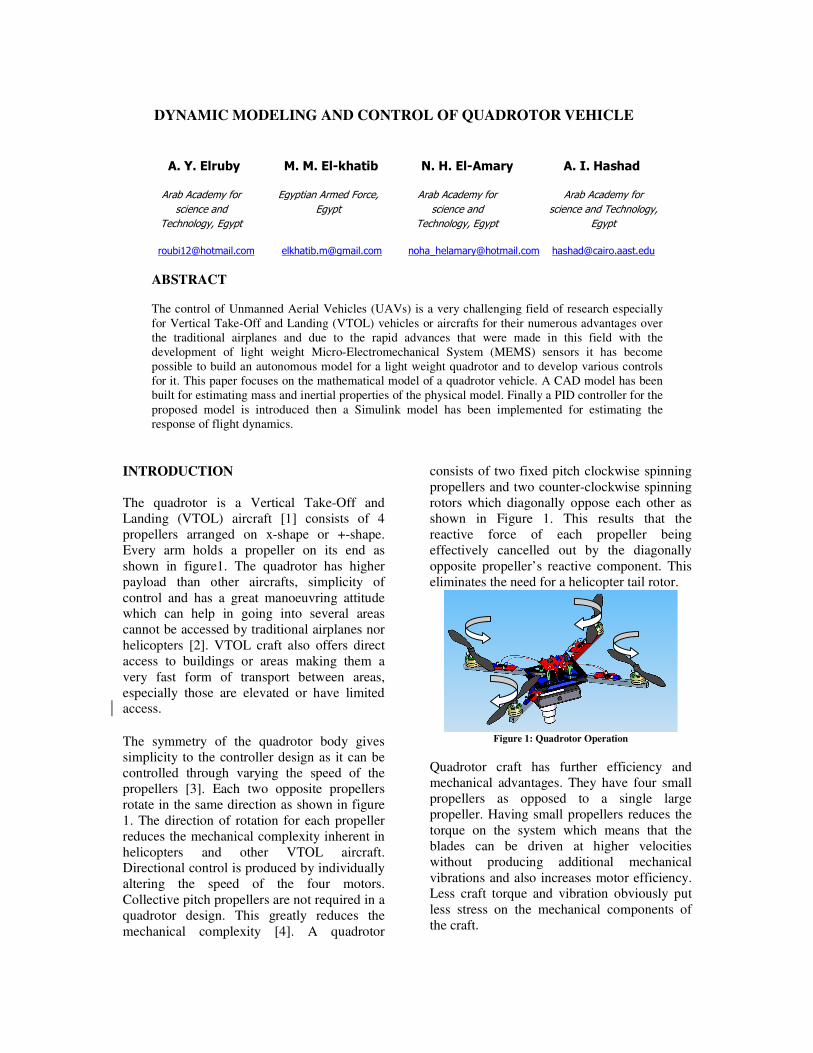
The quadrotor is a Vertical Take-Off and Landing (VTOL) aircraft [1] consists of 4 propellers arranged on x-shape or +-shape. Every arm holds a propeller on its end as shown in figure1. The quadrotor has higher payload than other aircrafts, simplicity of control and has a great manoeuvring attitude which can help in going into several areas cannot be accessed by traditional airplanes nor helicopters [2]. VTOL craft also offers direct access to buildings or areas making them a very fast form of transport between areas, especially those are elevated or have limited access.
The symmetry of the quadrotor body gives simplicity to the controller design as it can be controlled through varying the speed of the propellers [3]. Each two opposite propellers rotate in the same direction as shown in figure 1. The direction of rotation for each propeller reduces the mechanical complexity inherent in helicopters and other VTOL aircraft. Directional control is produced by individually altering the speed of the four motors. Collective pitch propellers are not required in a quadrotor design. This greatly reduces the mechanical complexity [4]. A quadrotor
consists of two fixed pitch clockwise spinning propellers and two counter-clockwise spinning rotors which diagonally oppose each other as shown in Figure 1. This results that the reactive force of each propeller being effectively cancelled out by the diagonally opposite propeller’s reactive component. This eliminates the need for a helicopter tail rotor.
Figure 1: Quadrotor Operation
Quadrotor craft has further efficiency and mechanical advantages. They have four small propellers as opposed to a single large propeller. Having small propellers reduces the torque on the system which means that the blades can be driven at higher velocities without producing additional mechanical vibrations and also increases motor efficiency. Less craft torque and vibration obviously put less stress on the mechanical components of the craft.
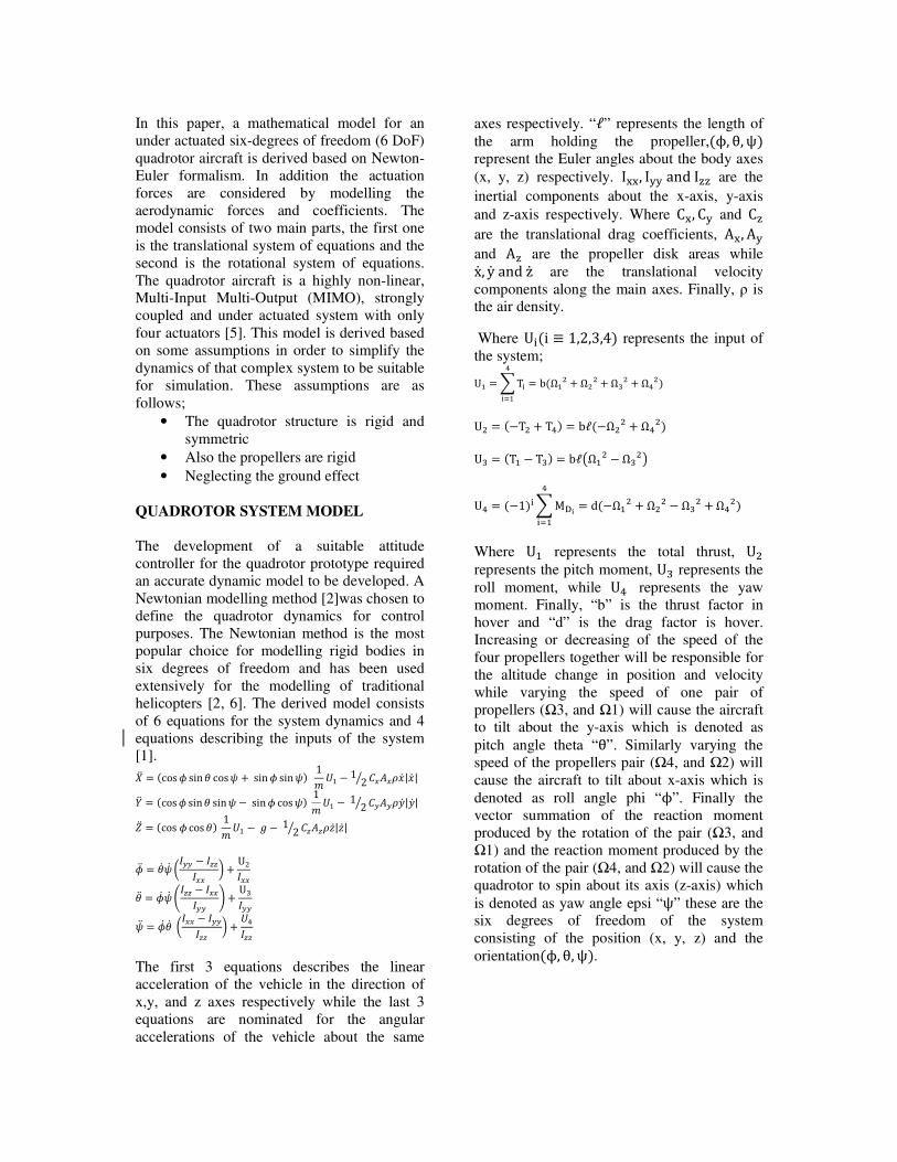
In this paper, a mathematical model for an under actuated six-degrees of freedom (6 DoF) quadrotor aircraft is derived based on Newton-Euler formalism. In addition the actuation forces are considered by modelling the aerodynamic forces and coefficients. The model consists of two main parts, the first one is the translational system of equations and the second is the rotational system of equations. The quadrotor aircraft is a highly non-linear, Multi-Input Multi-Output (MIMO), strongly coupled and under actuated system with only four actuators [5]. This model is derived based on some assumptions in order to simplify the dynamics of that complex system to be suitable for simulation. These assumptions are as follows;
• The quadrotor structure is rigid and symmetric
• Also the propellers are rigid • Neglecting the ground effect
QUADROTOR SYSTEM MODEL The development of a suitable attitude controller for the quadrotor prototype required an accurate dynamic model to be developed. A Newtonian modelling method [2]was chosen to define the quadrotor dynamics for control purposes. The Newtonian method is the most popular choice for modelling rigid bodies in six degrees of freedom and has been used extensively for the modelling of traditional helicopters [2, 6]. The derived model consists of 6 equations for the system dynamics and 4 equations describing the inputs of the system [1].
= cos sin cos +sin sin 1 − 1 2 | | = cos sin sin −sin cos 1 −1 2 | | ! = cos cos 1 − " −1 2 ##$|$|
= %& − &##& ' + U)& = *&## − && + + U,& = %& − &&## ' + -&## The first 3 equations describes the linear acceleration of the vehicle in the direction of x,y, and z axes respectively while the last 3 equations are nominated for the angular accelerations of the vehicle about the same
axes respectively. “ℓ” represents the length of the arm holding the propeller,ϕ, θ,ψ represent the Euler angles about the body axes (x, y, z) respectively. I44, I55andI88 are the inertial components about the x-axis, y-axis and z-axis respectively. Where C4, C5 and C8 are the translational drag coefficients, A4, A5 and A8 are the propeller disk areas while x , y andz are the translational velocity components along the main axes. Finally, ρ is the air density.
Where U>i ≡ 1,2,3,4 represents the input of the system;
U =BT>-
>D= bΩ) + Ω)) +Ω,) + Ω-)
U) = −T) + T- = bℓ−Ω)) + Ω-) U, = T − T, = bℓGΩ) −Ω,)H
U- = −1>BMJK
-
>D= d−Ω) + Ω)) − Ω,) +Ω-)
Where U represents the total thrust, U) represents the pitch moment, U, represents the roll moment, while U- represents the yaw moment. Finally, “b” is the thrust factor in hover and “d” is the drag factor is hover. Increasing or decreasing of the speed of the four propellers together will be responsible for the altitude change in position and velocity while varying the speed of one pair of propellers (Ω3, and Ω1) will cause the aircraft to tilt about the y-axis which is denoted as pitch angle theta “θ”. Similarly varying the speed of the propellers pair (Ω4, and Ω2) will cause the aircraft to tilt about x-axis which is denoted as roll angle phi “ϕ”. Finally the vector summation of the reaction moment produced by the rotation of the pair (Ω3, and Ω1) and the reaction moment produced by the rotation of the pair (Ω4, and Ω2) will cause the quadrotor to spin about its axis (z-axis) which is denoted as yaw angle epsi “ψ” these are the six degrees of freedom of the system consisting of the position (x, y, z) and the orientationϕ, θ, ψ.

Figure 2: axes notation
COMPUTER AIDED DESIGN MODEL The CAD model was built up using SolidEdge ST in order to estimate the mass of the vehicle and its inertial properties in order to use them in the simulation parameters. The assembly of the model is shown in figure 1 while the total estimated mass is equal to 688 grams and the inertial properties about the main axes X,Y, and Z can be found in table 2
Axis Mass Moment
Inertia
Radii of
Gyration
X 0.003325 kg.m^2 88.19 mm
Y 0.003263 Kg.m^2 87.36 mm
Z 0.006430 Kg.m^2 122.64 mm
MATLAB/SIMULINK MODELLING
A Matlab/simulink model was built using Matlab 2009 in order to simulate the systems dynamics and response under various conditions figure 3 shows the complete simulink model of the system
Figure 3: Simulink model
The model was built such that it has 4 inputs which are the desired altitude and the desired attitude of the quadrotor
CONTROLLER DESIGN AND TUNING
Given time restraints, a PID controller was selected to provide attitude control for the quadrotor craft.
The Euler angles are used as a feedback to the proposed controller in order to achieve the desired orientation. It may be used in the future with a path way trajectory controller which is not our concern in this study.
The traditional implementation can be defined as follows according to [7]:
dt
deKe(τ(τ)Ke(t)KOutput(t) d
t
0
ip ++= ∫
Where pK is proportional gain, iK is integral
gain, dK is derivative gain and e(t) is defined
as the difference between the actual controlled variable value and a desired valued. The quadrotor controller will be targeted at forcing the attitude angles to desired set points. As a result e(t) can be defined as:
Yaw MeasuredpointSet (t)e
Pitch MeasuredpointSet (t)e
Roll MeasuredpointSet (t)e
yaw
pitch
roll
−=
−=
−=
There are two main controllers in our system, first the attitude controller which is shown in figure 4. The controller has 3 inputs; the desired Euler angles and it takes the actual Euler angles values as a feedback and it calculates the appropriate control inputs U) pitch moment, U, roll moment, while U- yaw moment.
Figure 4: Attitude controller block

The altitude controller is similar to the attitude controller but it only controls the position of the craft along the z axis. It means that it only controls the altitude of the craft. It has the desired altitude as an input in addition to the actual altitude as a feedback signal while the output is the appropriate thrust force that keeps the craft at the desired altitude. Both controllers were manually tuned.
Figure 5: Altitude controller block
STEP RESPONSE OF THE SYSTEM The system was tested for a step input to the desired altitude and the output is shown in figure 5
Figure 6: Step response of Z
The system response is fast and has an acceptable overshoot in addition to small steady state error The system response for a step input to the desired phi was not as better as the response of the system to the desired altitude figure 7 shows the response. The system reaches the desired phi after 80 sec and with about 10% steady state error which is not acceptable
Figure 7: Step response of Phi
Theta response is similar to the phi response and this is due to the similarity in dynamic equations which came from the symmetry of the quadrotor structure. PULSE RESPONSE OF THE SYSTEM The system was tested for a pulse input of desired altitude equal to 5m for 4 sec and then it should reach the zero altitude again and figure 8 shows the response of the system
. Figure 8: Pulse response of Z
The response of the system for a desired phi pulse was not sufficient and it is not acceptable figure 9 shows the response of the system again it reaches the desired input after very long time about 80 sec in addition to a very large over shoot percent of the input.
Figure 9: Pulse response of Phi
CONCLUSION The quadrotor model mathematical model was different than the other built models as it included the drag forces along the 3 axes in addition to the coupling between the translation dynamics and the angular dynamics. The mass and the inertial properties that had been achieved from the CAD model
were used in the simulation. The PID controller used is sufficient and suitable for controlling the altitude of the quadrotor craft but it is not sufficient for controlling the attitude or Euler angles of the quadrotor craft. The system equations of the model shows that the Euler angles dynamics is independent and it does not rely on the translational dynamics while the translational dynamics is dependent on the angular dynamics, this is clear from the equations of motion of translation as they are function of Phi, Theta, and Psi. In future, an artificial intelligent controller may be introduced for the attitude controller of the same model in order to achieve a better performance. The major drawback in our model is that the motor dynamics is not included which will be affecting the dynamics of system it can be added in the future work of this research REFERENCES [1] V. MARTÍNEZ, "Modelling of the
Flight Dynamics of a Quadrotor Helicopter," in Aerospace Sciences.
vol. Master of Science: Cranfield, 2007.
[2] K. P. Valavanis, Advances in Unmanned Aerial Vehicles vol. 33.
Florida: Springer, 2007.
[3] T. Bresciani, "Modelling, Identification and Control of a Quadrotor Helicopter," in Automatic Control. vol. Master of Science
Sweden: Lund, 2008. [4] G. M. H. Haomiao Huang, Steven
L. Waslander and Claire J. Tomlin, "Aerodynamics and Control of Autonomous Quadrotor Helicopters in Aggressive Maneuvering," in
IEEE International Conference on Robotics and Automation Kobe, Japan, 2009.
[5] D.-b. W. Ashfaq Ahmad MIAN, "Dynamic modeling and nonlinear control strategy for an underactuated quad rotor rotorcraft," Zhejiang University SCIENCE, vol. 249, 2008.
[6] D. P. RAYMER, Aircraft Design: A Conceptual Approach. Washington: AIAA, 2004.
[7] M. M. Atheer L. Salih, Haider A. F. Mohamed and Khalaf Sallom Gaeid, "Modelling and PID Controller Design for a Quadrotor Unmanned Air Vehicle," in IEEE International Conference on Automation Quality and
Testing Robotics (AQTR) Cluj-Napoca 2010.